Q9S-AWR991TWO-WAY RADIO
Northfield Telecommunications, Inc. d/b/a Advanced Wireless Communications
Click to zoom
Application Details
- Equipment Class
- TNF - Licensed Non-Broadcast Transmitter Held to Face
- Date of Grant
- Feb 02, 2013
- Application Purpose
- Original Equipment
- Date of Application
- Feb 02, 2013
- Equipment Note
- TWO-WAY RADIO
- Frequency Range
- 450.02500000 - 469.97500000
- Country
- United States
Documents & Files
Document Text
Text extracted from the exhibit documents filed with the FCC. Open a document above to read the original.
Users Manual
FCC ID:Q9S-AWR991 AWR-991 SAFETYTRAINING INFORMATION Yo u r Northfield Telecommunications, Inc. d/b/a Advanced Wireless Communications radio generates RF electromagnetic energy during transmit mode. This radio is designed for and classified as “Occupational Use Only”, meaning it must be used only during the course of employment by individuals aware of the hazards, and the ways to minimize such hazards. This radio is NOT intended for use by the “General Population” in an uncontrolled environment. This radio has been tested and complies with the FCC RF exposure limits for “Occupational Use Only”. In addition, your Northfield Telecommunications, Inc. d/b/a Advanced Wireless Communications radio complies with the following Standards and Guidelines with regard to RF energy and electromagnetic energy levels and evaluation of such levels for exposure to humans: FCC OET Bulletin 65 Edition 97-01 Supplement C, Evaluating Compliance with FCC Guidelines for Human Exposure to Radio Frequency Electromagnetic Fields. American National Standards Institute (C95.1-1992), IEEE Standard for Safety Levels with Respect to Human Exposure to Radio Frequency Electromagnetic Fields, 3 kHz to 300 GHz. American National Standards Institute (C95.3-1992), IEEE Recommended Practice for the Measurement of Potentially Hazardous Electromagnetic Fields– RF and Microwave. The following accessories are authorized for use with this product. Use of accessories other than those (listed in the instruction) specified may result in RF exposure levels exceed the FCC requirements for wireless RF exposure. To ensure that your expose to RF electromagnetic energy is within the FCC allowable limits for occupational use, always adhere to the following guidelines: DO NOT operate the radio without a proper antenna attached, as this may damaged the radio and may also cause you to exceed FCC RF exposure limits. A proper antenna is the antenna supplied with this radio by the manufacturer or antenna specifically authorized by the manufacturer for use with this radio. DO NOT transmits for more than 50% of total radio use time (“50%duty cycle”). Transmitting more than 50% of the time can cause FCC RF exposure compliance requirements to be exceeded. The radio is transmitting when the “TX indicator” lights red. You can cause the radio to transmit by pressing the “PTT” switch. ALWAYS keep the antenna at least 30 cm (1 inch) away from the body when transmitting and only use the HYT belt-clip which is listed in instructions when attaching the radio to your belt, etc., to ensure FCC RF exposure compliance requirements are not exceeded. To provide the recipients of your transmission the best sound quality, hold the antenna at least 15cm from your mouth, and slightly off to one side. T he information listed above provides the user with the information needed to make him or her aware of RF exposure, and what to do to as‐sure that this radio operates with the FCC RF exposure limits of this radio. Electromagnetic Interference/Compatibility During transmissions, your Northfield Telecommunications, Inc. d/b/a Advanced Wireless Communications radio generates RF energy that can possibly cause interference with other devices or systems. To avoid such interference, turn off the radio in areas where signs are posted to do so. DO NOT operate the transmitter in areas that are sensitive to electromagnetic radiation such as hospitals, aircraft, and blasting sites. Occupational/Controlled Use The radio transmitter is used in situations in which persons are exposed as consequence of their employment provided those persons are fully aware of the potential for exposure and can exercise control over their exposure.
Attestation Statements
Jan.21, 2013 PHOENIX TESTLAB GmbH Koenigswinkel 10 D‐32825 Blomberg, Germany Subject: FCC ID: Q9S-AWR991 Attestation statement of the authorized use and the exact frequencies Gentlemen; The equipment meets the requirements of the FCC Rules, Part 90.203(e) and (g), as applicable. Programming of this product’s transmit frequencies can be performed ONLY by the manufacturer or by service or maintenance personal. The operator cannot be program transmit frequencies using the equipment’s external operation controls. Sincerely, Northfield Telecommunications, Inc. d/b/a Advanced Wireless Communications Peter Blakeley/Vice President
Attestation Statements
Jan.21, 2013 Federal Communications Commission Authorization & Evaluation Division 7435 Oakland Mills Road Colombia, Maryland 21046 Subject: FCC ID: Q9S‐AWR991 Justification Letter for Expanded Frequency Range 450MHz to 470MHz Gentlemen; You have asked Northfield Telecommunications, Inc. d/b/a Advanced Wireless Communications for justification to have the freq range 450MHz to 470MHz appears on the face of the FCC Grant of Certification for a Part 90 Certification. This frequency range is regarded as usual & customary by United States Federal Government and its various departments, user organizations and the military to appear on the face of the equipment Grant of Certification. Sincerely, Northfield Telecommunications, Inc. d/b/a Advanced Wireless Communications Peter Blakeley/Vice President
Cover Letter(s)
Jan.21, 2013 Federal Communication Commission Authorization and Evaluation Division FCC ID: Q9S-AWR991 Re: Confidentiality Request Pursuant to Sections 0.457 and 0.459 of the Commission’s Rules, the applicant hereby requests confidential treatment of information applied this application as outlined below: 1: Block Diagram 2: Circuit Diagram 3: Operational Description 4: Parts List 5:Tune Up Procedure The above materials contain trade secrets and proprietary information not customarily released to the public. The public disclosure of these matters might be harmful to the applicant and provide unjustified benefits to its competitors. The Applicant understands that pursuant to Rules 0.457, disclosure of this Application and all accompanying documentation will not be made before the date of the Grant for this application. Sincerely, Northfield Telecommunications, Inc. d/b/a Advanced Wireless Communications Peter Blakeley/Vice President
External Photos
EXTERNAL VIEW OF EUT WHOLE VIEW OF EUT TOP VIEW OF EUT BOTTOM VIEW OF EUT FRONT VIEW OF EUT BACK VIEW OF EUT LEFT VIEW OF EUT RIGHT VIEW OF EUT
ID Label/Location Info
FCC ID Label Location TWO-WAY RADIO FCC ID: Q9S‐AWR991 Model : AWR-991 Brand: ADVANCED WIRELESS COMMUNICATIONS Fre quency Range: 450MHz to 470MHz
ID Label/Location Info
Northfield Telecommunications, Inc. d/b/a Advanced Wireless Communications 20809 Kensington Blvd.Lakeville Minnesota 55044 United States Date: Jan.21, 2013 Statement We, Northfield Telecommunications, Inc. d/b/a Advanced Wireless Communications states that our device, FCC ID: Q9S‐AWR991, has no space to put the label except the battery compartment of this device. It is visible to the users as they purchase the products and install the battery. Sincerely, Northfield Telecommunications, Inc. d/b/a Advanced Wireless Communications Peter Blakeley/Vice President
Internal Photos
OPEN VIEW-1 OF EUT OPEN VIEW-2 OF EUT INTERNAL VIEW-1 OF EUT INTERNAL VIEW-2 OF EUT
RF Exposure Info
Report No.: AGC07B130101F7 Page 1 of 8 OET Bulletin 65 (MPE) Test Report Report No.: AGC07B130101F7 FCC ID : Q9S‐AWR991 PRODUCT DESIGNATION : TWO‐WAY RADIO BRAND NAME : ADVANCED WIRELESS COMMUNICATIONS TEST MODEL : AWR‐991 CLIENT : Northfield Telecommunications, Inc. d/b/a Advanced Wireless Communications DATE OF ISSUE : Jan.17, 2013 STANDARD(S) : OET Bulletin 65 REPORT VERSION : V1.0 Attestation of Global Compliance (Shenzhen) Co., Ltd. CAUTION: This report shall not be reproduced except in full without the written permission of the test laboratory and shall not be quoted out of context. Report No.: AGC07B130101F7 Page 2 of 8 TABALE OF CONTENTS TABALE OF CONTENTS .................................................................................................................................. 2 1. TEST RESULT CERTIFICATION ................................................................................................................... 3 2. TECHNICAL INFORMATION ......................................................................................................................... 4 3. RF EXPOSURE MEASUREMENT ................................................................................................................. 5 3.1 INTRODUCTION ...................................................................................................................................... 5 3.2 FCC LIMITS FOR MAXIMUM PERMISSIBLE EXPOSURE (MPE) .......................................................... 6 4. CLASSIFICATION OF THE ASSESSMENT METHODS ............................................................................... 7 5. EUT OPERATION CONDITION ..................................................................................................................... 7 6. TEST RESULTS ............................................................................................................................................. 8 Report No.: AGC07B130101F7 Page 3 of 8 1. TEST RESULT CERTIFICATION Applicant Name: Northfield Telecommunications, Inc. d/b/a Advanced Wireless Communications Address: 20809 Kensington Blvd.Lakeville Minnesota 55044 United States Manufacturer Name: CHINA NEW CENTURY(QUANZHOU) COMMUNICATION ELECTRONICS CO., LTD. Address: NO.1 FENGSHOU ROAD,ZHAOFENG INDUSTRIAL AREA,QUANZHOU CITY, FUJIAN PROVINCE China Product Designation TWO-WAY RADIO Brand Name ADVANCED WIRELESS COMMUNICATIONS Test Model AWR-991 Hardware Version: N/A Software Version: N/A Test Standard OET Bulletin 65 File Number: AGC07B130101F7 Date of Test: Jan.15, 2013 to Jan.17, 2013 We (AGC), Attestation of Global Compliance (Shenzhen) Co., Ltd. for compliance with the requirements set forth in the FCC Standard OET Bulletin 65 (Edition 97-01) Supplement C (Edition 01-01). The results of testing in this report apply to the product/system which was tested only. Tested by Wall Huang Jan.17, 2013 Checked By Forrest Lei Jan.17, 2013 Authorized By Solger Zhang Jan.17, 2013 Report No.: AGC07B130101F7 Page 4 of 8 2. TECHNICAL INFORMATION Note: the following data is based on the information by the applicant. EUT DESCRIPTION The EUT is a TWO-WAY RADIO designed for voice communication. It is designed by way of utilizing the FM modulation achieves the system operating. A major technical description of EUT is described as following: Communication Type Voice / Tone only Type of Modulation F3E Emission Bandwidth 8.81KHz Peak Frequency Deviation 1.77KHz Audio Frequency Response 10.98dB Maximum Transmitter Power 32.26dBm Rating Power 32.55dBm (It was fixed by the manufacturer; any individual can’t arbitrarily change it.) Antenna Designation Detachable Power Supply 3.7V by battery Power adapter parameter Input: AC 100~250V/50, 60Hz Output: DC 6V, 800mA & 4.2V, 300mA Limiting Voltage DC 3.15V Operation Frequency Range and Channel Frequency Range: 450MHz to 470MHz Channel Separation: 12.5KHz Top Channel: 450.025MHz Middle Channel: 460.000MHz Bottom Channel: 469.975MHz Frequency Tolerance 0.179ppm Report No.: AGC07B130101F7 Page 5 of 8 3. RF EXPOSURE MEASUREMENT 3.1 INTRODUCTION Human exposure to RF emissions from mobile devices (47 CFR §2.1091) may be evaluated based on the MPE limits adopted by the FCC for electric and magnetic field strength and/or power density, as appropriate, since exposures are assumed to occur at distances of 20 cm or more from persons. The 1992 ANSI/IEEE standard (See Listed limit table) specifies a minimum separation distance of 20 cm for performing reliable field measurements to determine adherence to MPE limits. If the minimum separation distance between a transmitter and nearby persons is more than 20 cm under normal operating conditions, compliance with MPE limits may be determined at such distance from the transmitter. When applicable, operation instructions and prominent warning labels may be used to alert the exposed persons to maintain a specified distance from the transmitter or to limit their exposure durations and usage conditions to ensure compliance. Report No.: AGC07B130101F7 Page 6 of 8 3.2 FCC LIMITS FOR MAXIMUM PERMISSIBLE EXPOSURE (MPE) LIMITS FOR GENERAL POPULATION / UNCONTROLLED EXPOSURE Frequency Range (MHz) E-field Strength (E) (V/m) Magnetic Field Strength (H) (A/m) Power Density (S) (mW/cm 2 ) Averaging Time |E| 2 , |H| 2 or S (Minutes) 0.3 -- 1.34 614 1.63 (100)* 30 1.34 -- 30 824/f 2.19/f (180/f 2 )* 30 30 -- 300 27.5 0.073 0.2 30 300 -- 1500 -- -- f/1500 30 1500 -- 100,000 -- -- 1.0 30 *Note: 1. f= Frequency in MHz * Plane-wave Equivalent Power Density 2. The averaging time for General Population/Uncontrolled exposure to fixed transmitters is not applicable for mobile and portable transmitters. See 47 CFR §§2.1091 and 2.1093 on source-based time-averaging requirement for mobile and portable transmitters. Report No.: AGC07B130101F7 Page 7 of 8 4. CLASSIFICATION OF THE ASSESSMENT METHODS According to user manual, The antenna of the product, under normal use condition is at least 0.3m away from …
Text truncated - open the document above for the full version.
Test Report
Report No.: AGC07B130101F2 Page 1 of 48 FCC Part 90 Test Report Report No.: AGC07B130101F2 FCC ID : Q9S‐AWR991 PRODUCT DESIGNATION : TWO‐WAY RADIO BRAND NAME : ADVANCED WIRELESS COMMUNICATIONS MODEL NAME : AWR‐991 CLIENT : Northfield Telecommunications, Inc. d/b/a Advanced Wireless Communications DATE OF ISSUE : Jan.17, 2013 STANDARD(S) : FCC Part 90 Rules REPORT VERSION : V 1.0 Attestation of Global Compliance (Shenzhen) Co., Ltd. CAUTION: This report shall not be reproduced except in full without the written permission of the test laboratory and shall not be quoted out of context. Report No.: AGC07B130101F2 Page 2 of 48 VERIFICATION OF COMPLIANCE Applicant: Northfield Telecommunications, Inc. d/b/a Advanced Wireless Communications 20809 Kensington Blvd.Lakeville Minnesota 55044 United States Manufacturer: CHINA NEW CENTURY(QUANZHOU) COMMUNICATION ELECTRONICS CO., LTD. NO.1 FENGSHOU ROAD,ZHAOFENG INDUSTRIAL AREA,QUANZHOU CITY, FUJIAN PROVINCE China Product Designation: TWO-WAY RADIO Brand Name: ADVANCED WIRELESS COMMUNICATIONS Model Name: AWR-991 Hardware Version: N/A Software Version: N/A Report No.: AGC07B130101F2 Date of Test: Jan.15, 2013 to Jan.17, 2013 WE HEREBY CERTIFY THAT: The above equipment was tested by Attestation of Global Compliance (Shenzhen) Co., Ltd. The data evaluation, test procedures, and equipment configurations shown in this report were made in accordance with the procedures given in ANSI C 63.4:2003. The sample tested as described in this report is in compliance with the FCC Rules Part 90 requirements The test results of this report relate only to the tested sample identified in this report. Tested by Wall Huang Jan.17, 2013 Checked By Forrest Lei Jan.17, 2013 Authorized By Solger Zhang Jan.17, 2013 Report No.: AGC07B130101F2 Page 3 of 48 TABLE OF CONTENTS 1. GENERAL INFORMATION .................................................................................................................. 5 1.1 PRODUCT DESCRIPTION ............................................................................................................. 5 1.2 RELATED SUBMITTAL(S) / GRANT (S) ......................................................................................... 6 1.3 TEST METHODOLOGY ................................................................................................................. 6 1.4 TEST FACILITY .............................................................................................................................. 6 1.5 SPECIAL ACCESSORIES .............................................................................................................. 6 1.6 EQUIPMENT MODIFICATIONS ..................................................................................................... 6 2. SYSTEM TEST CONFIGURATION ..................................................................................................... 7 2.1 EUT CONFIGURATION .................................................................................................................. 7 2.2 EUT EXERCISE ............................................................................................................................. 7 2.3 GENERAL TECHNICAL REQUIREMENTS .................................................................................... 7 2.4 CONFIGURATION OF TESTED SYSTEM .................................................................................... 7 3. SUMMARY OF TEST RESULTS ......................................................................................................... 8 4. DESCRIPTION OF TEST MODES ....................................................................................................... 9 5. CONDUCTED LIMITS ........................................................................................................................ 10 5.1 PROVISIONS APPLICABLE ......................................................................................................... 10 5.2 MEASUREMENT PROCEDURE .................................................................................................. 10 5.3 TEST SETUP BLOCK DIAGRAM ................................................................................................. 11 5.4 TEST EQUIPMENT USED ............................................................................................................ 11 5.5 TEST RESULT .............................................................................................................................. 12 6. FREQUENCY TOLERANCE .............................................................................................................. 14 6.1 PROVISIONS APPLICABLE ......................................................................................................... 14 6.2 MEASUREMENT PROCEDURE .................................................................................................. 14 6.3 TEST SETUP BLOCK DIAGRAM ................................................................................................. 15 6.4 TEST EQUIPMENT USED: ........................................................................................................... 15 6.5 TEST RESULT .............................................................................................................................. 16 7. EMISSION BANDWIDTH ................................................................................................................... 19 7.1 PROVISIONS APPLICABLE ......................................................................................................... 19 7.2 MEASUREMENT PROCEDURE .................................................................................................. 19 7.3 TEST SETUP BLOCK DIAGRAM ................................................................................................. 19 7.4 MEASUREMENT EQUIPMENT USED: ........................................................................................ 19 7.5 MEASUR…
Text truncated - open the document above for the full version.
Test Setup Photos
RADIATED EMISSION TEST SETUP CONDUCTED EMISSION TEST SETUP
Contact Information
Applicant
Kenneth J Coons(President)
Test Firm
Attestation of Global Compliance Shenzhen Co. Ltd.Forrest Lei
Technical Specifications
| # | Rule Parts | Frequency Range | Power Output | Emission | Tolerance |
|---|---|---|---|---|---|
| 1 | 90 | 450.025 MHz - 469.975 MHz | 1.683 W | 8K81F3E | 0.1790000000 ppm |
Other Applications from Northfield Telecommunications, Inc. d/b/a Advanced Wireless Communications
Q9SRB5000DU
Aug 21, 2026Base Station
Equipment Class
CSR - Scanning Receiver
Q9SAWR4002DU
Feb 17, 2024Two-way radio
Equipment Class
JAV - Other Non-Digital SDoC Devices
Q9SCMB307
Dec 12, 2023Two-way radio
Equipment Class
DTS - Digital Transmission System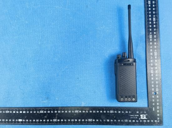
Q9SAWRD5500
Jul 20, 2023Two Way Radio
Equipment Class
TNF - Licensed Non-Broadcast Transmitter Held to Face
Q9SAWRDRP9050S
Oct 02, 2022Digital Repeater
Equipment Class
TNB - Licensed Non-Broadcast Station Transmitter