Q9SAWRDRP9050SDigital Repeater
Northfield Telecommunications, Inc. d/b/a Advanced Wireless Communications
Click to zoom
Application Details
- Equipment Class
- TNB - Licensed Non-Broadcast Station Transmitter
- Date of Grant
- Oct 02, 2022
- Application Purpose
- Original Equipment
- Date of Application
- Oct 02, 2022
- Equipment Note
- Digital Repeater
- Frequency Range
- 406.10000000 - 470.00000000
- Country
- United States
Documents & Files
Document Text
Text extracted from the exhibit documents filed with the FCC. Open a document above to read the original.
Users Manual
To user Thanks! Digital repeater (is briefly referred to as repeater below), use the high performance radio frequency module, Control panel, Power supply module and Built-in duplexer (Optional), designed as 50w professional repeater. Repeater use the modular design, with high performance and easy to maintain, convenient to update and the interface opening features. Repeater main functions are wireless transfer, support local PTT calling and support expanding function, is convenient for users to add other communication functions, which will bring a lot of convenience for your work and life. R epeater use the most advanced and superb technology hope our quality will satisfy you. Contents USER INSTRUCTIONS ················································································· 2 SAFETY PRECAUTIONS ··············································································· 3 OOBA ·············································································································4 PRODUCT INTRODUCTION ·········································································· 4 FRONT PANEL INTRODUCTION ·········································································· 4 PANEL INTRODUCTION ···················································································· 4 FUNCTION INTRODUCTION ··············································································5 REPEATER OPERATION ··············································································· 8 TURN ON/TURN OFF REPEATER ·········································································8 INDICATATION OF TRANSIT···············································································8 SOFTWARE OPERATION ·············································································· ····9 PANEL KEY OPERATION AND DIGITAL DISPLAY ·············································· ··· 9 PANEL OPERATION ····················································································· 12 OVERALL FRAMEWORK····························································································12 SET UP DISPLAY ·································································································· ·· 12 PASSWORD AUTHENTICATION··················································································· 16 SHORTCUTS ····································································································· 16 TROUBLESHOOTING GUIDE ········································································ 16 User instructions ◆ Would you please read this manual carefully before using this product, so that you can more easily handle the operation of this machine. When you use this product, we think that you have read t he instructions already.。 ◆ Please carefully keep this instruction for future reference. ◆ In order to safeguard the legitimate rights and interests of you, so please seriously truthfully fill in the user's warranty Card " when buying our products, and ask for the purchase vouchers. ◆ Because this product relates to upgrade and improve, the company reserves the rights of changing the soft specifications without prior notice to at any time in this manual.This manual mentioned product specifications and information is only for reference. Safety Precautions For the safety and effectiveness of your operation, please read bellow information carefully. ◆High voltage and high temperature, be careful for electric shock and burn ◆ Maintenance work must be professionals and technicals, don’t dismounting. ◆Setting and install must be approved of the radio administrative department. ◆ Repeater has the ground terminal, which should be carefully ground for the safety and performance of the machine. ◆The installation of the antenna must be the lightning protection measure, otherwise may cause serious lost. ◆Please use the qualified antenna, anti-thunder, feeder, power divider to make sure the correct of installation OOBA Please be careful when open the packing box,confirm whether has goods inside of the box, if you find something miss or been damage, please contact dealer. Item No. Repeater 1 AC power supply line 1 USB data line 1 Microphone 1 Coaxial cable (for duplexer) 1 User manual 1 Warranty Card 1 Product Introduction Front panel introduction Front view F ront panel larger view Indicator Color Functional description TX green Always on, the repeater is transmitting signals RX green Always on, the repeater is receiving signals LNK green Always on, the link is successful ERROR red On or flashes, error occured DC green Always on, DC power supply equipment POWER green TS B transmit A、B green Digital time slot one receive signal, A light on. Digital time slot two, B light on. Analog doesn’t light. Digital tube (two bits) instruction Including two bits eight segments digital tube, the function as below: 1) Instruct current working channel number during working condition. 2) Use to display current menu option or some function parameter figures during key operation 3) Display current error code when the repeater appear warning. Front panel board MIC interface Front panel board MIC interface use to internet microphone, local PTT can be use as talking or use as base station to call. Key function detailed description Button Name Menu guide function Parameter editor function C 1.short press back to up menu or root menu 2. long press back to standby mode and lock the keyboard Clear or cancel current parameter value Left 1. Up level menu 2. Shortcut menu: decrease channel Value decrease Right 1. Next level menu 2. Shortcut menu, increase channel Value increase Ok Enter next level menu Confirm and save current parameter value F1 Function key 1 (software defines) Figure 1 F2 Function key 2 (software defines) Figure 2 F3/v_ 1.Function key 3 (software defines) 2.Shortcuts menu: volume down Figure 3 F4/v+ 1.Function key 4 (software defines) 2.Shortcuts menu: volume up Fig…
Text truncated - open the document above for the full version.
External Photos
EXHIBIT B - EUT EXTERNAL PHOTOGRAPHS
Internal Photos
EXHIBIT C - EUT INTERNAL PHOTOGRAPHS
RF Exposure Info
China Certification ICT Co., Ltd (Dongguan) Report No.: CR21110034-00B Page 44 of 44 5. RF EXPOSURE EVALUATION 5.1 FCC Maximum Permissible Exposure (MPE) 5.1.1 Applicable Standard According to subpart §1.1310, systems operating under the provisions of this section shall be operated in a manner that ensures that the public is not exposed to radio frequency energy level in excess of the Commission’s guidelines. 5.1.2 Limits Maximum Permissible Exposure (MPE) (§1.1310, §2.1091) Limits for Occupational/Controlled Exposure Frequency Range (MHz) Electric Field Strength (E) (V/m) Magnetic Field Strength (H) (A/m) Power Density (S) (mW/cm 2 ) Averaging Time |E|, |H| or S (minutes) 0.3- 3.0 614 1.63 (100)* 6 3.0 - 30 1842/f 4.89/f (900/f 2 )* 6 30-300 61.4 0.163 1.0 6 300-1500 / / f/300 6 1500-100,000 / / 5 6 f = frequency in MHz; * = Plane-wave equivalent power density; According to §1.1310 and §2.1091 RF exposure is calculated. 5.1.3 Calculated Formulary: Predication of MPE limit at a given distance S = PG/4R² = power density (in appropriate units, e.g. mW/cm 2 ); P = power input to the antenna (in appropriate units, e.g., mW); G = power gain of the antenna in the direction of interest relative to an isotropic radiator, the power gain factor, is normally numeric gain; R = distance to the center of radiation of the antenna (appropriate units, e.g., cm); 5.1.4 Calculated Data Frequency Band (MHz) Maximum Tune-up Conducted Power (dBm) Antenna Gain (dBi) Evaluation Distance (cm) Power Density (mW/cm 2 ) MPE Limit (mW/cm 2 ) 400-470 47.5 5.0 110 1.17 1.33 Result: Compliant, The device meet MPE requirement at 110 cm distance. ***** END OF REPORT *****
Test Report
TEST REPORT Applicant: Northfield Telecommunications, Inc. d/b/a Advanced Wireless Communications Address: 20809 Kensington Blvd, Lakeville, Minnesota, United States 55044 FCC ID: Q9SAWRDRP9050S Product Name: Digital Repeater Model Number: AWR-DRP9050S Standard(s): 47 CFR Part 2 47 CFR Part 90 ANSI C63.26-2015 ANSI/TIA 603-E-2016 The above equipment has been tested and found compliance with the requirement of the relative standards by China Certification ICT Co., Ltd (Dongguan) Report Number: CR21110034-00B Date Of Issue: 2022-03-07 Reviewed By: Sun Zhong Title: Manager Test Laboratory: China Certification ICT Co., Ltd (Dongguan) No. 113, Pingkang Road, Dalang Town, Dongguan, Guangdong, China Tel: +86-769-82016888 China Certification ICT Co., Ltd (Dongguan) Report No.: CR21110034-00B Page 2 of 44 Test Facility The Test site used by China Certification ICT Co., Ltd (Dongguan) to collect test data is located on the No. 113, Pingkang Road, Dalang Town, Dongguan, Guangdong, China. The lab has been recognized as the FCC accredited lab under the KDB 974614 D01 and is listed in the FCC Public Access Link (PAL) database, FCC Registration No. : 442868, the FCC Designation No. : CN1314. The lab has been recognized by Innovation, Science and Economic Development Canada to test to Canadian radio equipment requirements, the CAB identifier: CN0123. Declarations China Certification ICT Co., Ltd (Dongguan) is not responsible for the authenticity of any test data provided by the applicant. Data included from the applicant that may affect test results are marked with a triangle symbol “▲”. Customer model name, addresses, names, trademarks etc. are not considered data. Unless otherwise stated the results shown in this test report refer only to the sample(s) tested. This report cannot be reproduced except in full, without prior written approval of the Company. This report is valid only with a valid digital signature. The digital signature may be available only under the Adobe software above version 7.0. This report may contain data that are not covered by the accreditation scope and shall be marked with an asterisk “★”. China Certification ICT Co., Ltd (Dongguan) Report No.: CR21110034-00B Page 3 of 44 CONTENTS T EST FACILITY .......................................................................................................................................... 2 DECLARATIONS .......................................................................................................................................... 2 1. GENERAL INFORMATION .................................................................................................... 5 1.1 PRODUCT DESCRIPTION FOR EQUIPMENT UNDER TEST (EUT) ....................................................... 5 1.2 DESCRIPTION OF TEST CONFIGURATION ........................................................................................... 6 1.2.2 Support Equipment List and Details .............................................................................................................. 6 1.2.3 Support Cable List and Details ...................................................................................................................... 6 1.2.4 Block Diagram of Test Setup ......................................................................................................................... 6 1.3 MEASUREMENT UNCERTAINTY .......................................................................................................... 7 2. SUMMARY OF TEST RESULTS ............................................................................................ 8 3. REQUIREMENTS AND TEST PROCEDURES .................................................................... 9 3.1 TRANSMITTER FREQUENCY STABILITY ............................................................................................. 9 3.1.1 Applicable Standard ....................................................................................................................................... 9 3.1.2 Test Procedure ............................................................................................................................................... 9 3.1.3 EUT Setup Block Diagram ............................................................................................................................ 9 3.2 TRANSMITTER OUTPUT POWER ....................................................................................................... 10 3.2.1 Applicable Standard ..................................................................................................................................... 10 3.2.2 Test Procedure ............................................................................................................................................. 10 3.2.3 EUT Setup Block Diagram .......................................................................................................................... 11 3.3 OCCUPIED BANDWIDTH & EMISSION MASK .................................................................................... 12 3.3.1 Applicable Standard ..................................................................................................................................... 12 3.3.2 Test Procedure ............................................................................................................................................. 12 3.3.3 EUT Setup Block Diagram .......................................................................................................................... 13 3.4 TRANSMITTER UNWANTED EMISSIONS(CONDUCTED) .................................................................... 14 3.4.1 Applicable Standard ..................................................................................................................................... 14 3.4.2 Test Procedure .................................................................................................…
Text truncated - open the document above for the full version.
Contact Information
Applicant
Kenneth J Coons(President)
Test Firm
CHINA CERTIFICATION ICT CO., LTD (DONGGUAN)Tanie Ou
[email protected]0086 0769 86858888
Technical Specifications
| # | Rule Parts | Frequency Range | Power Output | Emission | Tolerance |
|---|---|---|---|---|---|
| 6 | 9 | 406.1 MHz - 470 MHz | 50 W | 7K60F1E | 1.5 ppm |
Other Applications from Northfield Telecommunications, Inc. d/b/a Advanced Wireless Communications

Q9SRB5000DU
Aug 21, 2026Base Station
Equipment Class
CSR - Scanning Receiver
Q9SAWR4002DU
Feb 17, 2024Two-way radio
Equipment Class
JAV - Other Non-Digital SDoC Devices
Q9SCMB307
Dec 12, 2023Two-way radio
Equipment Class
DTS - Digital Transmission System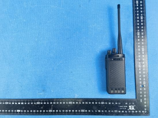
Q9SAWRD5500
Jul 20, 2023Two Way Radio
Equipment Class
TNF - Licensed Non-Broadcast Transmitter Held to Face
Q9SAWRD7000N
Jun 08, 2021Two Way Radio
Equipment Class
CXX - Communications Rcvr for use w/ licensed Tx and CBs