Q9SHD-1000V2Two-Way Radio
Northfield Telecommunications, Inc. d/b/a Advanced Wireless Communications
Click to zoom
Application Details
- Equipment Class
- TNF - Licensed Non-Broadcast Transmitter Held to Face
- Date of Grant
- Oct 25, 2010
- Application Purpose
- Original Equipment
- Date of Application
- Oct 25, 2010
- Equipment Note
- Two-Way Radio
- Frequency Range
- 450.00000000 - 470.00000000
- Country
- United States
Documents & Files
Document Text
Text extracted from the exhibit documents filed with the FCC. Open a document above to read the original.
Users Manual
HD-1000V2 GENERAL/概述 INTRODUCTION SCOPEOFTHISMANUAL familiarwithsimilartypesofcommercial gradecommunications equipment.It containsallrequiredserviceinformationforthe equipmentandis currentasof thepublicationdate.Changes BulletinsorManualRevisions.Theseareissuedasrequired. ORDERINGREPLACEMENTPARTS Whenorderingreplacementpartsorequipmentinformation, appliesto allparts:components,kits,orchassis.If thepart componentfor properidentification. PERSONALSAFETY Thefollowingprecautionsarerecommendedforpersonal safety: • DONOTtransmituntilallRFconnectorsareverifiedsecure andanyopenconnectorsareproperly terminated. • blastingcapsorin anexplosive •Thisequipmentshouldbeservicedbya qualified technician only. SERVI CE Thisradiois designedforeasyservicing.Refertotheschematic diagrams,printedcircuitboardviews, and alignmentprocedures containedwithin. 0.5W/1W 0.5W/1W 引言 本手册的范围 本手册是提供给熟悉通信专业并且具有维修经验的技术人员 使用的。 替换零件的订购 当订购替换零件或设备信息时,应注明完整的零件识别号码。 所有的零件均有识别号码:元件、组件或机壳。如果不知道 零件的号码,为了正确地识别,必须注明此元件所属的机壳 或组件的号码,并对元件进行充分的说明。 个人安全 为了个人的安全,请注意下列事项: •在没有认真核实所有射频插头之前或有任何一个打开的插头 没有连接到响应端子上的情况下,均不要发射。 •在电爆管附近或在易燃性气体环境中,必须关掉电源,不要 操作本设备 •本设备只应该由有资格的技术人员来维修。 维修服务 为了便于维修本设备,建立了完整的维修服务体系,提供了 包括原理图、印刷线路图和调整步骤在内的资料供参考。 信道数量 射频输出功率 RFPowerOutput Numberofchannels Thismanualis intendedforusebyexperiencedtechnicians whichmayoccurafterpublicationarecoveredbyeither Service 它包括了维修该设备所 需要的全部资料和现行公布 后可能发生变动,如果需要,可以使用《维修 thefullpartidentificationnumbershouldbe included.This numberis notknown,include thechassisor kitnumberof SHUTOFFandDONOT operatethisequipmentnear electrical whichit is a part,anda sufficientdescriptionof therequired 的数据。在出版 通报》或《手册修订本》进行补充。 199 199 SAFETYTRAINING INFORMATION Your radio generates RF electromagnetic energy during transmit mode. This radio is designed for and classified as “Occupational Use Only”, meaning it must be used only during the course of employment by individuals aware of the hazards, and the ways to minimize such hazards. This radio is NOT intended for use by the “General Population” in an uncontrolled environment. This radio has been tested and complies with the FCC RF exposure limits for “Occupational Use Only”. In addition, yourradio complies with the following Standards and Guidelines with regard to RF energy and electromagnetic energy levels and evaluation of such levels for exposure to humans: FCC OET Bulletin 65 Edition 97-01 Supplement C, Evaluating Compliance with FCC Guidelines for Human Exposure to Radio Frequency Electromagnetic Fields. American National Standards Institute (C95.1-1992), IEEE Standard for Safety Levels with Respect to Human Exposure to Radio Frequency Electromagnetic Fields, 3 kHz to 300 GHz. American National Standards Institute (C95.3-1992), IEEE Recommended Practice for the Measurement of Potentially Hazardous Electromagnetic Fields– RF and Microwave. The following accessories are authorized for use with this product. Use of accessories other than those (listed in the instruction) specified may result in RF exposure levels exceeding the FCC requirements for wireless RF exposure. To ensure that your expose to RF electromagnetic energy is within the FCC allowable limits for occupational use, always adhere to the following guidelines: DO NOT operate the radio without a proper antenna attached, as this may damaged the radio and may also cause you to exceed FCC RF exposure limits. A proper antenna is the antenna supplied with this radio by the manufacturer or antenna specifically authorized by the manufacturer for use with this radio. DO NOT transmits for more than 50% of total radio use time (“50%duty cycle”). Transmitting more than 50% of the time can cause FCC RF exposure compliance requirements to be exceeded. The radio is transmitting when the “TX indicator” lights red. You can cause the radio to transmit by pressing the “PTT” switch. ALWAYS keep the antenna at least 2.5 cm (1 inch) away from the body when transmitting and only use the belt-clip which is listed in instructions when attaching the radio to your belt, etc., to ensure FCC RF exposure compliance requirements are not exceeded. To provide the recipients of your transmission the best sound quality, hold the antenna at least 5 cm (2 inches) from your mouth, and slightly off to one side. The information listed above provides the user with the information needed to make him or her aware of RF exposure, and what to do to as-sure that this radio operates with the FCC RF exposure limits of this radio. Electromagnetic Interference/Compatibility During transmissions, your radio generates RF energy that can possibly cause interference with other devices or systems. To avoid such interference, turn off the radio in areas where signs are posted to do so. DO NOT operate the transmitter in areas that are sensitive to electromagnetic radiation such as hospitals, aircraft, and blasting sites. Occupational/Controlled Use The radio transmitter is used in situations in which persons are exposed as consequence of their employment provided those persons are fully aware of the potential for exposure and can exercise control over their exposure. IMPORTANT READ ALL INSTRUCTIONS carefully and completely before using the transceiver SAVE THIS INSTRUCTION MANUAL- This instruction manual contains important operating instructions for the Two-Way Radio EXPLICIT DEFINITIONS WORD DEFINITION WARNING Personal injury, fire hazard or electric shock may occur. CAUTION Equipment damage may occur. NOTE If disregarded, inconvenience only. No risk of personal injury, fire or electric shock. OPERATING NOTES When transmitting with a portable radio, hold the radio in a vertical position with its microphone 5 to 10 cm (2 to 4 inches) away from your mouth. Keep the antenna at least 2.5 cm (1 inch) from your head and body. If you wear a portable two-way radio on your body, ensure that the antenna is at least 2.5 centimeters (1 inch) from your body when transmitting. PRECAUTIONS WARNING! NEVER hold the transceiver so that the antenna is…
Text truncated - open the document above for the full version.
Cover Letter(s)
Oct. 12, 2010 Federal Communications Commission Authorization & Evaluation Division 7435 Oakland Mills Road Colombia, Maryland 21046 Subject: FCC ID: Q9SHD-1000V2 Attestation statement that the end user can’t tune the transmitter. Gentlemen; The equipment meets the requirements of the FCC Rules, Part 90.203(e) and (g), as applicable. Programming of this product’s transmit frequencies can be performed ONLY by the manufacturer or by service or maintenance personal. The operator cannot be program transmit frequencies using the equipment’s external operation controls. Northfield Telecommunications, Inc. Peter (Vice President)
Cover Letter(s)
Oct. 12, 2010 Federal Communications Commission Authorization & Evaluation Division 7435 Oakland Mills Road Colombia, Maryland 21046 1) The device is handheld. Subject: FCC Label Location Justification Letter We hereby declare that Northfield Telecommunications, Inc. Two-way Radio of HD-1000V2 which intended to bear the FCC ID: Q9SHD-1000V2 shall be marketed as following: 2) The FCC identifier is visible at the time of purchase. Marketing the device without the battery installed when the label is in the battery compartment is acceptable. The FCC identifier on the box or additional documentation directing the user as to where to find the FCC label also satisfies this requirement. 3) The user accessible area must not require any special tools for access and the FCC label must not be placed on a removable part. (i.e. not on battery cover) 4) The FCC identifier, model no. or FCC logo must be on the label and must meet all general labeling requirements or policies that apply for Certification, Verification or DOC; e.g. for Certification, for handheld devices, the identifier must go on the label but the two part warning statement in Section 15.19(a) 3 can go in the manual. Sincerely yours Northfield Telecommunications, Inc. Peter/ Vice President
External Photos
TOP VIEW OF EUT BOTTOM VIEW OF EUT LEFT VIEW OF EUT RIGHT VIEW OF EUT FRONT VIEW OF EUT BACK VIEW OF EUT
ID Label/Location Info
FCC ID Label Location FCC RF WARNING LABEL
ID Label/Location Info
FCC ID Label FCC RF WARNING LABEL
Internal Photos
VIEW OF PCB-1 VIEW OF PCB-2 VIEW OF PCB-3 VIEW OF PCB-4
RF Exposure Info
NO.: RZA2009-0627-1 TEST REPORT Test name Electromagnetic Field (Specific Absorption Rate) Product TWO-WAY RADIO Model HD-1000V2 FCC ID Q9SHD-1000V2 Client Northfield Telecommunications, Inc. TA Technology (Shanghai) Co., Ltd. TA Technology (Shanghai) Co., Ltd. Test Report No. RZA2009-0627-1 Page 2of 65 GENERAL TERMS 1. The test report is invalid if not marked with “exclusive stamp for the data report” or the stamp of the TA. 2. Any copy of the test report is invalid if not re-marked with the “exclusive stamp for the test report” or the stamp of TA. 3. The test report is invalid if not marked with the stamps or the signatures of the persons responsible for performing, revising and approving the test report. 4. The test report is invalid if there is any evidence of erasure and/or falsification. 5. If there is any dissidence for the test report, please file objection to the test center within 15 days from the date of receiving the test report. 6. Normally, entrust test is only responsible for the samples that have undergone the test. 7. This test report cannot be used partially or in full for publicity and/or promotional purposes without previous written permissions of TA. Address: Room4,No.399,Cailun Rd,Zhangjiang Hi-Tech Park, Pudong Shanghai,China Post code: 201203 Telephone: +86-021-50791141/2/3 Fax:+86-021-50791141/2/3-8000 Website: http://www.ta-shanghai.com E-mail: [email protected] TA Technology (Shanghai) Co., Ltd. Test Report No. RZA2009-0627-1 Page 3of 65 GENERAL SUMMARY Product TWO-WAY RADIO Model HD-1000V2 Client Northfield Telecommunications, Inc. Type of test Entrusted Manufacturer CHINA NEW CENTURY(QUANZHOU) COMMUNICATION ELECTRONICS., LTD Arrival Date of sample May 21 th , 2010 Place of sampling (Blank) Carrier of the samples Eason Zhao Quantity of the samples One Date of product (Blank) Base of the samples (Blank) Items of test SAR Series number / Standard(s) IEEE C95.1–2005: IEEE Standard for Safety Levels with Respect to Human Exposure to Radio Frequency Electromagnetic Fields, 3 kHz to 300 GHz. IEEE 1528–2003: Recommended Practice for Determining the Peak Spatial-Average Specific Absorption Rate (SAR) in the Human Head Due to Wireless Communications Devices: Experimental Techniques. OET Bulletin 65 supplement C, published June 2001 including DA 02-1438, published June 2002: Additional Information for Evaluating Compliance of Mobile and Portable Devices with FCC Limits. Transition Period for the Phantom Requirements of Supplement C to OET Bulletin 65. IEC 62209-1: Human exposure to radio frequency fields from hand-held and body-mounted wireless communication devices – Human models, instrumentation, and procedures –Part 1: Procedure to determine the Specific Absorption Rate (SAR) for hand-held devices used in close proximity to the ear (frequency range of 300 MHz to 3 GHz). IEC 62209-2:2008(106/162/CDV): Human exposure to radio frequency fields from handheld and body-mounted wireless communication devices – Human models, instrumentation, and procedures –Part 2: Procedure to determine the Specific Absorption Rate (SAR)for wireless communication devices used in close proximity to the human body .( frequency rang of 30MHz to 6GHz ) Conclusion Localized Specific Absorption Rate (SAR) of this portable wireless equipment has been measured in all cases requested by the relevant standards cited in Clause 7.2 of this test report. Maximum localized SAR is below exposure limits specified in the relevant standards cited in Clause 7.1 of this test report. General Judgment: Pass (Stamp) Date of issue: August 19 th , 2010 Comment The test result only responds to the measured sample. Approved by Weizhong Yang Revised by Minbao Ling Performed by Lu Wang TA Technology (Shanghai) Co., Ltd. Test Report No. RZA2009-0627-1 Page 4of 65 TABLE OF CONTENT 1. COMPETENCE AND WARRANTIES..................................................................................... 6 2. GENERAL CONDITIONS....................................................................................................... 6 3. DESCRIPTION OF EUT ........................................................................................................ 7 3.1. A DDRESSING INFORMATION RELATED TO EUT ..........................................................................7 3.2. C ONSTITUENTS OF EUT ..........................................................................................................7 3.3. T EST ITEM..............................................................................................................................8 3.4. G ENERAL DESCRIPTION..........................................................................................................8 4. OPERATIONAL CONDITIONS DURING TEST ..................................................................... 9 5. SAR MEASUREMENTS SYSTEM CONFIGURATION.......................................................... 9 5.1. SAR MEASUREMENT SET-UP...................................................................................................9 5.2. D ASY4 E-FIELD PROBE SYSTEM............................................................................................10 5.2.1. ET3DV6 Probe Specification .......................................................................................10 5.2.2. E-field Probe Calibration .............................................................................................. 11 5.3. O THER TEST EQUIPMENT......................................................................................................12 5.3.1. Device Holder for Transmitters ....................................................................................12 5.3.2. Phantom......................................................................................................................12 5.4. S CANNING PROCEDURE.........................................................................................................13 5.5. D ATA STORAGE AND EVALUATI…
Text truncated - open the document above for the full version.
Test Report
FCC Part 90 & RSS-119 Test Report For TWO-WAY RADIO Model Name: HD-1000V2 Brand Name: ADVANCED WIRELESS COMMUNICATIONS FCC ID: Q9SHD-1000V2, IC ID: 4651A-HD1000V2 Report No.: AGC100810007SZ09-1F2 Date of Issue: Aug.03, 2010 Prepared For Northfield Telecommunications, Inc. 20809 Kensington Blvd, Lakeville, MN. United States, 55044 TEL: FAX: Prepared By Attestation of Global Compliance Co., Ltd. 2F., No.2 Building, Huafeng No.1 Technical Industrial Park, Sanwei, Xixiang, Baoan District, Shenzhen TEL: 86-755-2908 1966 FAX: 86-755-2600 8484 Report No.: AGC10081007SZ09-1F2 Page 1 of 45 VERIFICATION OF COMPLIANCE Applicant: Northfield Telecommunications, Inc. 20809 Kensington Blvd, Lakeville, MN. United States, 55044 Manufacturer: CHINA NEW CENTURY (QUANZHOU) COMMUNICATION ELECTRONICS CO., LTD No.1 Fengshou Road, Zhaofeng Industrial Area, Quanzhou City, Fujian Province, China Product Description: TWO-WAY RADIO Brand Name: ADVANCED WIRELESS COMMUNICATIONS Model Number: HD-1000V2 File Number: AGC10081007SZ09-1F2 Date of Test: Jul.28 to Aug.03, 2010 We hereby certify that: The above equipment was tested by Attestation of Global Compliance Co., Ltd. The data evaluation, test procedures, and equipment configurations shown in this report were made in accordance with the procedures given in ANSI C 63.4:2003 and TIA/EIA 603. The sample tested as described in this report is in compliance with the FCC Rules Part 90 and RSS-119 The test results of this report relate only to the tested sample identified in this report. Checked By: Jekey Zhang Aug.03, 2010 Authorized By King Zhang Aug.03, 2010 Report No.: AGC10081007SZ09-1F2 Page 2 of 45 TABLE OF CONTENTS 1. GENERAL INFORMATION ............................................................................................. 4 1.1 PRODUCT DESCRIPTION ....................................................................................................................... 4 1.2 RELATED SUBMITTAL(S) / GRANT (S) ................................................................................................. 5 1.3 TEST METHODOLOGY ........................................................................................................................... 5 1.4 TEST FACILITY ........................................................................................................................................ 5 1.5 SPECIAL ACCESSORIES ....................................................................................................................... 5 1.6 EQUIPMENT MODIFICATIONS ............................................................................................................... 5 2. SYSTEM TEST CONFIGURATION ................................................................................. 6 2.1 EUT CONFIGURATION ............................................................................................................................ 6 2.2 EUT EXERCISE ........................................................................................................................................ 6 2.3 GENERAL TECHNICAL REQUIREMENTS............................................................................................. 6 2.4 CONFIGURATION OF TESTED SYSTEM ............................................................................................. 6 3. SUMMARY OF TEST RESULTS .................................................................................... 7 4. DESCRIPTION OF TEST MODES .................................................................................. 8 5. FREQUENCY TOLERANCE ........................................................................................... 9 5.1 PROVISIONS APPLICABLE .................................................................................................................... 9 5.2 MEASUREMENT PROCEDURE .............................................................................................................. 9 5.2 TEST SETUP BLOCK DIAGRAM .......................................................................................................... 10 5.3 TEST EQUIPMENT USED: .................................................................................................................... 10 5.4 TEST RESULT ........................................................................................................................................ 10 6. EMISSION BANDWIDTH .............................................................................................. 13 6.1 PROVISIONS APPLICABLE .................................................................................................................. 13 6.2 MEASUREMENT PROCEDURE ............................................................................................................ 13 6.3 TEST SETUP BLOCK DIAGRAM .......................................................................................................... 13 6.4 MEASUREMENT EQUIPMENT USED: ................................................................................................. 13 6.5 MEASUREMENT RESULT: .................................................................................................................... 14 7. UNWANTED RADIATION ............................................................................................. 16 7.1 PROVISIONS APPLICABLE .................................................................................................................. 16 7.2 MEASUREMENT PROCEDURE ............................................................................................................ 16 7.3 TEST SETUP BLOCK DIAGRAM .......................................................................................................... 17 7.5 MEASUREMENT RESULTS: ................................................................................................................. 19 7.6 EMISSION MASK PLOT ......................................................................…
Text truncated - open the document above for the full version.
Test Setup Photos
RADIATED TEST SETUP
Contact Information
Applicant
Kenneth J Coons(President)
Test Firm
Attestation of Global Compliance Shenzhen Co. Ltd.Forrest Lei
Technical Specifications
| # | Rule Parts | Frequency Range | Power Output | Emission | Tolerance |
|---|---|---|---|---|---|
| 2 | 9 | 450 MHz - 470 MHz | 930.00 mW | 16K0F3E | 2.5 ppm |
Other Applications from Northfield Telecommunications, Inc. d/b/a Advanced Wireless Communications
Q9SRB5000DU
Aug 21, 2026Base Station
Equipment Class
CSR - Scanning Receiver
Q9SAWR4002DU
Feb 17, 2024Two-way radio
Equipment Class
JAV - Other Non-Digital SDoC Devices
Q9SCMB307
Dec 12, 2023Two-way radio
Equipment Class
DTS - Digital Transmission System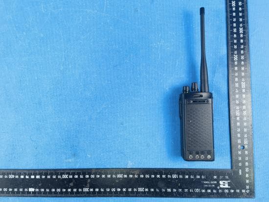
Q9SAWRD5500
Jul 20, 2023Two Way Radio
Equipment Class
TNF - Licensed Non-Broadcast Transmitter Held to Face
Q9SAWRDRP9050S
Oct 02, 2022Digital Repeater
Equipment Class
TNB - Licensed Non-Broadcast Station Transmitter