QC8-AN100UAWireless Access Base Station
Redline Communications Inc.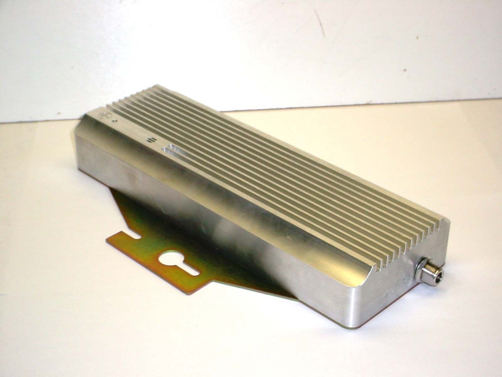
Click to zoom
Application Details
- Equipment Class
- TNB - Licensed Non-Broadcast Station Transmitter
- Date of Grant
- Nov 04, 2007
- Application Purpose
- Original Equipment
- Date of Application
- Jul 18, 2007
- Equipment Note
- Wireless Access Base Station
- Frequency Range
- 3650.00000000 - 3675.00000000
- Company
- Redline Communications Inc.
- Country
- Canada
Documents & Files
Document Text
Text extracted from the exhibit documents filed with the FCC. Open a document above to read the original.
Users Manual
Doc. #70-00058-01-01 Proprietary Redline Communications © 2007 July 13, 2007 Page 1 of 117 RedMAX TM AN-100U Single Sector Wireless Access Base Station User Manual RedMAX ™ Base Station User Manual Doc. #70-00058-01-01 Proprietary Redline Communications © 2007 July 13, 2007 Page 2 of 117 Copyright Information All rights reserved July 13, 2007. The information in this document is proprietary to Redline Communications Inc. This document may not in whole or in part be copied, reproduced, or reduced to any medium without prior consent, in writing, from Redline Communications Incorporated. Contact Information: Redline Communications Inc. 302 Town Centre Blvd. Suite 100 Markham, ON Canada L3R 0E8 Web Site: http://www.redlinecommunications.com Sales Inquiries: North American: [email protected] Toll-free sales: 1-866-633-6669 International: [email protected] Support: www.redlinecommunications.com/support/support_portal.html Document Control: 70-00058-01-01-RedMAX_BaseStation_AN-100U_User-FCC-20070713a.doc Disclaimer The statements, configurations, technical data, and recommendations in this document are believed to be accurate and reliable, but are presented without express or implied warranty. Additionally, Redline makes no representations or warranties, either expressed or implied, regarding the contents of this product. Redline Communications shall not be liable for any misuse regarding this product. The information in this document is subject to change without notice. RedMAX ™ Base Station User Manual Doc. #70-00058-01-01 Proprietary Redline Communications © 2007 July 13, 2007 Page 3 of 117 TABLE OF CONTENTS 1 Important Safety & Service Notices..................................................... 11 1.1 Safety Warnings ...................................................................................... 11 1.2 Important Warning Symbols .................................................................... 12 1.3 Frequency Selection................................................................................ 12 1.3.1 General................................................................................................ 12 1.4 FCC Notice .............................................................................................. 13 1.4.1 R&TTE Directive 1999/5/EC Statements............................................. 13 1.5 Important Service Information ................................................................. 15 1.6 Information For Use In Canada ............................................................... 16 1.7 WEEE Product Return Process............................................................... 17 2 RedMAX Base Station Overview .......................................................... 18 2.1 Introduction.............................................................................................. 18 2.2 IEEE 802.16 / WiMAX Compliance ......................................................... 18 2.3 PHY Specification.................................................................................... 19 2.4 OFDM (256 FFT) ..................................................................................... 19 2.5 Features .................................................................................................. 19 2.5.1 Privacy................................................................................................. 19 2.5.2 Time Division Duplexing (TDD) ........................................................... 19 2.5.3 Coding Rate......................................................................................... 20 2.5.4 Modulation ........................................................................................... 20 2.5.5 Reed Solomon Error Correction .......................................................... 20 2.5.6 Time Synchronization .......................................................................... 20 2.6 Deployment Models................................................................................. 20 2.6.1 PTP Deployment ................................................................................. 21 2.6.2 PMP Deployment................................................................................. 21 2.6.3 Non Line-of-Sight................................................................................. 21 2.6.4 Channelization..................................................................................... 22 2.7 Service Flows .......................................................................................... 22 2.7.1 Service Flow Classification.................................................................. 23 2.7.2 Dynamic Service Addition.................................................................... 23 2.7.3 Default Service Flows.......................................................................... 23 2.7.4 Scheduling........................................................................................... 23 Real-Time Polling Service (rt-PS)........................................................ 23 Non-Real-Time Polling Service (nrt-PS).............................................. 24 Best Effort (BE) ................................................................................... 24 Unsolicited Grant Service (UGS)......................................................... 24 Traffic Scheduling Algorithm ............................................................... 24 3 Physical Description ............................................................................. 25 3.1 Base Station Terminal (IDU) ................................................................... 25 3.1.1 Mounting.............................................................................................. 25 3.1.2 Power Supply ...................................................................................... 25 3.1.3 Wireless Section..........................................…
Text truncated - open the document above for the full version.
Attestation Statements
www.redlinecommunications.com July 4, 2007 Federal Communications Commission Authorization and Evaluation Division Confidentiality Request regarding application for certification of FCC ID: QC8-AN100UA. Pursuant to Sections 0.457 and 0.459 of the Commission’s Rules, we hereby request confidential treatment of information accompanying this application as outlined below: Block diagrams (AN100U-block.pdf) Schematic diagrams (AN100U-schematic_TB3638F7.pdf) Parts List (AN100U-BOM_TB3638F7.pdf) The above materials contain trade secrets and proprietary information not customarily released to the public. The public disclosure of these materials may be harmful to the applicant and provide unjustified benefits to its competitors. The applicant understands that pursuant to Section 0.457 of the Rules, disclosure of this application and all accompanying documentation will not be made before the date of the Grant for this application. If you have any queries, please do not hesitate to contact us by our TOLL FREE numbers: OUR TELEPHONE NO.: 1-866-OFDMNOW Sincerely, Medhat I. Fawzy, P.Eng Compliance Manager Tel. (905) 479-8344 x2443 Fax. (905) 479-5331 e-mail: [email protected] 302 Town Centre Blvd., Suite 100, Markham, ON Canada, L3R 0E8 Bus: 905.479.8344 Fax: 905.479.7432
Attestation Statements
Contention Based Protocol Redline Communications AN-100U Wireless Broadband System Part 90 – Private Land mobile Radio Services Sub-Part Z – 3650 MHz Wireless Broadband Services Revision 1 June 2007 Table of Contents 1 Introduction...................................................................................................3 1.1 Purpose...................................................................................................................3 1.2 Requirement............................................................................................................3 2 The Redline RedMax System..............................................................................3 2.1 System configuration..................................................................................................3 2.2 Standards based.........................................................................................................3 2.3 Distributed Functionality..............................................................................................3 3 Network Entry.................................................................................................3 3.1 Introduction.............................................................................................................3 3.2 General Description....................................................................................................4 3.3 GPS (global positioning system).....................................................................................4 3.4 Network Entry Contention based Ranging and Automatic Parameters Adjustments.........................5 4 Glossary and References....................................................................................6 4.1 Definitions and Abbreviations........................................................................................6 4.2 References...............................................................................................................6 5 Conclusions.....................................................................................................7 6 Contacts.........................................................................................................7 Table of Figures Figure 1 Uplink Intervals....................................................................................5 2 1 Introduction 1.1 Purpose This document constitutes a submission for equipment certification purposes for the Redline Communications RedMax AN-100U system transmitters in the 3650-3700 MHz band, subject to the rules and requirements of CFR 47 Part 90, Sub-part Z. It specifically describes the methodology used to meet the requirement that each transmitter employ a contention based protocol (CBP). 1.2 Requirement Paragraph (o) of section 90.203 in sub-part Z identifies that applications for certification must describe the methodology used to meet the CBP requirement on each transmitter. Section 90.7 defines the CBP as follows: “A protocol that allows multiple users to share the same spectrum by defining the events that must occur when two or more transmitters attempt to simultaneously access the same channel and establishing rules by which a transmitter provides reasonable opportunities for other transmitters to operate. Such a protocol may consist of procedures for initiating new transmissions, procedures for determining the state of the channel (available or unavailable), and procedures for managing retransmissions in the event of a busy channel.” 2 The Redline RedMax System 2.1 System configuration The Redline RedMax wireless broadband system that would be deployed in the 3650 – 3700MHz band comprises devices identified as sector controllers (called the AN-100U) and devices identified as subscriber units. The AN- 100U Sector controllers are usually deployed with sectorial antennas covering an area that can be populated with a number of subscriber units. This is a typical Point to Multipoint configuration and the number of subscriber stations can range from one to many tens of units. In this arrangement, the subscriber stations are under the control of the sector controller which will allocate transmission resources to subscriber stations as the need to pass traffic arises. For the purposes of this document, an active sector under the control of a sector controller is considered a network. Once a subscriber station has been accepted into the network then its transmission time and bandwidth resources are scheduled in terms of receiving data from the sector controller (downlink) and when it may respond with transmissions in an uplink direction. However there has to be an opportunity for new subscriber stations to join the network and this aspect will be described further. 2.2 Standards based The Redline AN-100U wireless broadband system is based on the IEEE 802.16 2004 air interface standard, which is the standard worldwide for the 3650 – 3700MHz band. 2.3 Distributed Functionality Section 90.203 identifies a requirement that each transmitter employ a CBP. In the Redline AN-100U system, the CBP functionality is a distributed implementation between the sector controller and the subscriber stations as a network function rather than specifically in each transmitting station. Neither of these stations would operate as a stand-alone transmitter. 3 Network Entry 3.1 Introduction The CBP definition states the need to define ”..... the events that must occur when two or more transmitters attempt to simultaneously access the same channel and establishing rules by which a transmitter provides reasonable opportunities for other transmitters to operate.”. This situation will occur when new subscriber stations attempt to 3 join the network and the following sections describe the process that occurs in the Redline RedMax wireless broadband system.4.1. Definitions and Abbreviation. 3.2 General Description Within a given frequency channel and BS antenna sector, all …
Text truncated - open the document above for the full version.
Attestation Statements
Antenna Gain: 20 dBi: A2014ARF Flat Panel Antenna: 1 foot, 13.5 degree, 20 dBi flat panel antenna (HD-MNT-KIT required). Channel Spacing: 7 MHz Freq. G ANT B GUI Setting PPSD (Cond.) PPSD EIRP PPSD EIRP Limit Margin (GHz) (dBi) (MHz) (dBm) (dBm/MHz) (dBm/MHz) (dBm/MHz) (dB) 3.6500 20.00 7.00 3.0 8.67 28.67 30.00 1.33 Channel Spacing: 3.5 MHz Freq. G ANT B GUI Setting PPSD (Cond.) PPSD EIRP PPSD EIRP Limit Margin (GHz) (dBi) (MHz) (dBm) (dBm/MHz) (dBm/MHz) (dBm/MHz) (dB) 3.6500 20.00 3.50 1.0 7.83 27.83 30.00 2.17 Antenna Gain: 17 dBi: PA1760EAS Premium Sector Antenna: 60 degree, High performance, vertical polarization, offers improved cross polarization and F/B performance. (requires HD-MNT, sold separately) Channel Spacing: 7 MHz Freq. G ANT B GUI Setting PPSD (Cond.) PPSD EIRP PPSD EIRP Limit Margin (GHz) (dBi) (MHz) (dBm) (dBm/MHz) (dBm/MHz) (dBm/MHz) (dB) 3.6500 17.00 7.00 6.0 10.83 27.83 30.00 2.17 Channel Spacing: 3.5 MHz Freq. G ANT B GUI Setting PPSD (Cond.) PPSD EIRP PPSD EIRP Limit Margin (GHz) (dBi) (MHz) (dBm) (dBm/MHz) (dBm/MHz) (dBm/MHz) (dB) 3.6500 17.00 3.50 3.0 10.67 27.67 30.00 2.33 Antenna Gain: 16 dBi: PA1660EASH Premium Sector Antenna: 60 degree, High performance, horizontal polarization, offers improved cross polarization and F/B performance. (requires HD-MNT, sold separately) Channel Spacing: 7 MHz Freq. G ANT B GUI Setting PPSD (Cond.) PPSD EIRP PPSD EIRP Limit Margin (GHz) (dBi) (MHz) (dBm) (dBm/MHz) (dBm/MHz) (dBm/MHz) (dB) 3.6500 16.00 7.00 8.0 12.67 28.67 30.00 1.33 Channel Spacing: 3.5 MHz Freq. G ANT B GUI Setting PPSD (Cond.) PPSD EIRP PPSD EIRP Limit Margin (GHz) (dBi) (MHz) (dBm) (dBm/MHz) (dBm/MHz) (dBm/MHz) (dB) 3.6500 16.00 3.50 5.0 12.00 28 30.00 2.00 Antenna Gain: 16 dBi: PA1690EAS Premium Sector Antenna: 90 degree, High performance, vertical polarization, offers improved cross polarization and F/B performance. (requires HD-MNT, sold separately) Channel Spacing: 7 MHz Freq. G ANT B GUI Setting PPSD (Cond.) PPSD EIRP PPSD EIRP Limit Margin (GHz) (dBi) (MHz) (dBm) (dBm/MHz) (dBm/MHz) (dBm/MHz) (dB) 3.6500 16.00 7.00 8.0 12.67 28.67 30.00 1.33 Channel Spacing: 3.5 MHz Freq. G ANT B GUI Setting PPSD (Cond.) PPSD EIRP PPSD EIRP Limit Margin (GHz) (dBi) (MHz) (dBm) (dBm/MHz) (dBm/MHz) (dBm/MHz) (dB) 3.6500 16.00 3.50 5.0 12.00 28 30.00 2.00 Antenna Gain: 15 dBi: PA1590EASH Premium Sector Antenna: 90 degree, High performance, horizontal polarization, offers improved cross polarization and F/B performance. (requires HD-MNT, sold separately) Channel Spacing: 7 MHz Freq. G ANT B GUI Setting PPSD (Cond.) PPSD EIRP PPSD EIRP Limit Margin (GHz) (dBi) (MHz) (dBm) (dBm/MHz) (dBm/MHz) (dBm/MHz) (dB) 3.6500 15.00 7.00 8.0 12.67 27.67 30.00 2.33 Channel Spacing: 3.5 MHz Freq. G ANT B GUI Setting PPSD (Cond.) PPSD EIRP PPSD EIRP Limit Margin (GHz) (dBi) (MHz) (dBm) (dBm/MHz) (dBm/MHz) (dBm/MHz) (dB) 3.6500 15.00 3.50 6.0 13.00 28 30.00 2.00 Antenna Gain: 14.5 dBi: A1490MTS Sector Antenna: 90 degree, High performance, vertical polarization, offers improved cross polarization and F/B performance. (requires HD-MNT, sold separately) Channel Spacing: 7 MHz Freq. G ANT B GUI Setting PPSD (Cond.) PPSD EIRP PPSD EIRP Limit Margin (GHz) (dBi) (MHz) (dBm) (dBm/MHz) (dBm/MHz) (dBm/MHz) (dB) 3.6500 14.50 7.00 9.0 13.83 28.33 30.00 1.67 Channel Spacing: 3.5 MHz Freq. G ANT B GUI Setting PPSD (Cond.) PPSD EIRP PPSD EIRP Limit Margin (GHz) (dBi) (MHz) (dBm) (dBm/MHz) (dBm/MHz) (dBm/MHz) (dB) 3.6500 14.50 3.50 6.0 13.00 27.5 30.00 2.50 Antenna Gain: 14 dBi: PA14120EAS Sector Antenna: 120 degree, High performance, vertical polarization, offers improved cross polarization and F/B performance. (requires HD-MNT, sold separately) Channel Spacing: 7 MHz Freq. G ANT B GUI Setting PPSD (Cond.) PPSD EIRP PPSD EIRP Limit Margin (GHz) (dBi) (MHz) (dBm) (dBm/MHz) (dBm/MHz) (dBm/MHz) (dB) 3.6500 14.00 7.00 9.0 13.87 27.87 30.00 2.13 Channel Spacing: 3.5 MHz Freq. G ANT B GUI Setting PPSD (Cond.) PPSD EIRP PPSD EIRP Limit Margin (GHz) (dBi) (MHz) (dBm) (dBm/MHz) (dBm/MHz) (dBm/MHz) (dB) 3.6500 14.00 3.50 7.0 14.33 28.33 30.00 1.67 Antenna Gain: 14 dBi: PA14120EASH Sector Antenna: 120 degree, High performance, horizontal polarization, offers improved cross polarization and F/B performance. (requires HD-MNT, sold separately) Channel Spacing: 7 MHz Freq. G ANT B GUI Setting PPSD (Cond.) PPSD EIRP PPSD EIRP Limit Margin (GHz) (dBi) (MHz) (dBm) (dBm/MHz) (dBm/MHz) (dBm/MHz) (dB) 3.6500 14.00 7.00 9.0 13.87 27.87 30.00 2.13 Channel Spacing: 3.5 MHz Freq. G ANT B GUI Setting PPSD (Cond.) PPSD EIRP PPSD EIRP Limit Margin (GHz) (dBi) (MHz) (dBm) (dBm/MHz) (dBm/MHz) (dBm/MHz) (dB) 3.6500 14.00 3.50 7.0 14.33 28.33 30.00 1.67 Antenna Gain: 11dBi: A11360EAOOmni Antenna: 360 degree (requires HD-MNT, sold separately)Channel Spacing: 7 MHz Freq. G ANT B GUI Setting PPSD (Cond.) PPSD EIRP PPSD EIRP Limit Margin (GHz) (dBi) (MHz) (dBm) (dBm/MHz) (dBm/MHz) (dBm/MHz) (dB) 3.6500 11.00 7.00 12.0 16.67 27.67 30.00 2.33 Channel Spacing: 3.5 MHz Freq. G ANT B GUI Setting PPSD (Cond.) PPSD EIRP PPSD EIRP Limit Margin (GHz) (dBi) (MHz) (dBm) (dBm/MHz) (dBm/MHz) (dBm/MHz) (dB) 3.6500 11.00 3.50 10.0 17.00 28 30.00 2.00
Attestation Statements
www.redlinecommunications.com 302 Town Centre Blvd., Suite 100, Markham, ON Canada, L3R 0E8 Bus: 905.479.8344 Fax: 905.479.7432 October 11, 2007 To: Mr. Steven Dayhoff [email protected] FCC Application Processing Branch Applicant: Redline Communications Inc FCC ID: QC8-AN100UA Form 731 Confirmation Number: EA549096 Date of Original E-Mail: 10/09/2007 Correspondence Reference Number: 33937 Dear Mr. Dayhoff, Thank you for your letter dated October 09, 2007 in regards to our application for the lower 25 MHz of the band (3650-3675 MHz-Part 90 Subpart Z for the Tx and Part 15 for the Rx). Q-i. Please explain what "WiMAX coordination among separate providers" means. Provide the technical details on the network impact and how is it done. A-i: "WiMAX coordination among separate providers" implies a number of things, which include: Special (site), Frequency, and time (Tx scheduling) coordination. Special coordination Assumes an adequate distance between BSs of separate operators such that the interference from one operator's BS or SSs on the other kept to a minimum. The effect of adding additional operator networks would thus result in a reduction in CINR which WiMAX addresses by adapting its modulation to a lower more robust level. Frequency coordination Interference, can also be mitigated by coordination of frequencies such that co-channels sectors are designed to face in opposite directions. These are standard practices employed during normal frequency planning exercises but would be extended across more than one operator such as to share a common frequency plan. Time (Tx scheduling) coordination On WiMAX TDD systems frequency coordination is further facilitated through a use of a common GPS based Tx time synchronization signal. Through the coordination of various WiMAX parameters such as OFDM frame duration, guard intervals, channel size, and BS Tx power. By agreeing on a common set of parameters and a similar frequency plan interference can be mitigated to acceptable levels such that each operator would be able to deliver acceptable performance. Q-ii . You state that anyone who buys our system only can share it with others. We understand this is WiMax protocol, but give details of how this is accomplished. A-ii: All CPEs only transmit initially during a planned contention period to get registered and then once registered they only transmit during the timeframe when they are specifically scheduled to transmit by the base station You can contact the undersigned if you have any questions. 2 Sincerely Yours, Medhat I. Fawzy, M. Eng, P.Eng Compliance Manager Ph: (905) 479-8344 x2443 Fax: (905) 479-5331 [email protected]
Cover Letter(s)
July 5, 2007 Federal Communication Commission 7435 Oakland Mills Road Columbia, MD 21046 USA Subject: Certification Application under FCC CFR 47, Parts 2 and 90 (Subpart Z) - Wireless Broadband Services in the 3650-3675 MHz. Applicant: Redline Communications Inc. Product: RedMAX Model: AN-100U with TB3638F7 Radio FCC ID: QC8-AN100UA Dear Sir/Madam, As appointed agent for Redline Communications Inc., we would like to submit the application for certification of the above product. Please review all required documents uploaded to your E-Filing web site. If you have any queries, please do not hesitate to contact us. Yours truly, Tri Minh Luu, P. Eng., V.P., Engineering UltraTech Group of Labs Ultratech’s Accreditations: 0685 31040/SIT C-1376 46390-2049 200093-0 SL2-IN-E-1119R 3000 Bristol Circle, Oakville, Ontario, Canada L6H 6G4 Tel.: (905) 829-1570 Fax.: (905) 829-8050 Website: www.ultratech-labs.com Email: [email protected] UltraTech Group of Labs Ultratech’s Accreditations: 0685 31040/SIT C-1376 46390-2049 200093-0 SL2-IN-E-1119R 3000 Bristol Circle, Oakville, Ontario, Canada L6H 6G4 Tel.: (905) 829-1570 Fax.: (905) 829-8050 Website: www.ultratech-labs.com Email: [email protected]
Cover Letter(s)
www.redlinecommunications.com July 4, 2007 FEDERAL COMMUNICATIONS COMMISSION 7435 Oakland Mills Road Columbia, MD 21046 U.S.A. Subject: Authority to Act as an Agent to FCC Applicant: Redline Communications Product: RedMAX Model: AN-100U with TB3638F7 Radio FCC ID: QC8-AN100UA Dear Sir/Madam, I hereby appoint UltraTech Engineering Labs Inc. (UltraTech) to act as my agent in preparation of this application to F.C.C. for authourization of equipment under F.C.C. Rules. I also certify that the information provided, properly described the device or system for which authourization is required. Regards, Medhat I. Fawzy, P.Eng Compliance Manager Tel. (905) 479-8344 x2443 Fax. (905) 479-5331 e-mail: [email protected] 302 Town Centre Blvd., Suite 100, Markham, ON Canada, L3R 0E8 Bus: 905.479.8344 Fax: 905.479.7432
External Photos
Annex 2 – External Photographs of Model AN-100U with TB3638F7 Radio Photo # 1 FCC ID: QC8-AN100UA In-door Unit Annex 2 – External Photographs of Model AN-100U with TB3638F7 Radio Photo # 2 FCC ID: QC8-AN100UA In-door Unit Annex 2 – External Photographs of Model AN-100U with TB3638F7 Radio Photo # 3 FCC ID: QC8-AN100UA Out-door Unit Annex 2 – External Photographs of Model AN-100U with TB3638F7 Radio Photo # 4 FCC ID: QC8-AN100UA Out-door Unit
Internal Photos
Annex 3 – Internal Photographs of Model AN-100U with TB3638F7 Radio Photo # 1 FCC ID: QC8-AN100UA In-door Unit Annex 3 – Internal Photographs of Model AN-100U with TB3638F7 Radio Photo # 2 FCC ID: QC8-AN100UA In-door Unit Annex 3 – Internal Photographs of Model AN-100U with TB3638F7 Radio Photo # 3 FCC ID: QC8-AN100UA In-door Unit Annex 3 – Internal Photographs of Model AN-100U with TB3638F7 Radio Photo # 4 FCC ID: QC8-AN100UA In-door Unit Annex 3 – Internal Photographs of Model AN-100U with TB3638F7 Radio Photo # 5 FCC ID: QC8-AN100UA In-door Unit Annex 3 – Internal Photographs of Model AN-100U with TB3638F7 Radio Photo # 6 FCC ID: QC8-AN100UA In-door Unit Annex 3 – Internal Photographs of Model AN-100U with TB3638F7 Radio Photo # 7 FCC ID: QC8-AN100UA In-door Unit Annex 3 – Internal Photographs of Model AN-100U with TB3638F7 Radio Photo # 8 FCC ID: QC8-AN100UA In-door Unit Annex 3 – Internal Photographs of Model AN-100U with TB3638F7 Radio Photo # 9 FCC ID: QC8-AN100UA Out-door Unit Annex 3 – Internal Photographs of Model AN-100U with TB3638F7 Radio Photo # 10 FCC ID: QC8-AN100UA Out-door Unit Annex 3 – Internal Photographs of Model AN-100U with TB3638F7 Radio Photo # 11 FCC ID: QC8-AN100UA Out-door Unit
Operational Description
AN-100U Overview REDMAX™ AN-100U WiMAX Certified Base Station Redline's RedMAX AN-100U is the world's first WiMAX Forum Certified™ base station. Easy and cost- effective to deploy, the RedMAX AN-100U facilitates the rapid provision of new fixed and nomadic wireless broadband services by service providers , while its very low latency ensures reliable delivery of time- sensitive services, including circuit-switched voice traffic, voice-over-Internet Protocol (VoIP), video and prioritized data traffic. The AN-100U design architecture enables 'over-the-air' upgrades in the field through simplified software downloads and the ability to dynamically “on-the-fly” customize individual Quality of Service (QoS) settings, according to the service level agreement (SLA). The RedMAX Base Station can be deployed in clusters of up to six (60 degree) sectors, supporting thousands of unique user-data flows and hundreds of simultaneous subscribers per sector. The GPS time synchronization feature ensures efficient use of available spectrum and channels, providing scalable and reliable dense cell deployment of Time Division Duplexing (TDD) base stations radios. The hardware is fully upgradeable in the field by software download, to accommodate such future enhancements as IPv6 support, scalability, additional classifiers, alternative encryption standards, and the continued development of the 802.16 standard. Adherence to stringent carrier-class NEBS Level 3 specifications provides high reliability for mission critical deployments. The indoor unit has a selection of radios for operation in the licensed and unlicensed bands using the 802.16-2004 specified 3.5 MHz and 7 MHz channel profiles.
Test Report
RedMAX Model No.: AN-100U with TB3638F7 Radio FCC ID: QC8-AN100UA Applicant: Redline Communications Inc. 302 Town Centre Blvd. Markham, Ontario Canada, L3R 0E8 Tested in Accordance With Federal Communications Commission (FCC) CFR 47, PARTS 2 and 90 (Subpart Z) Wireless Broadband Services in the 3650-3675 MHz UltraTech's File No.: RCI-175FCC90Z This Test report is Issued under the Authority of Tri M. Luu, Professional Engineer, Vice President of Engineering UltraTech Group of Labs Date: July 5, 2007 Report Prepared by: Dharmajit Solanki, RF Engineer Tested by: Wayne Wu, RFI Engineer Issued Date: July 5, 2007 Test Dates: June 25-29, 2007 The results in this Test Report apply only to the sample(s) tested, and the sample tested is randomly selected. This report must not be used by the client to claim product endorsement by NVLAP or any agency of the US Government. UltraTech 3000 Bristol Circle, Oakville, Ontario, Canada, L6H 6G4 Tel.: (905) 829-1570 Fax.: (905) 829-8050 Website: www.ultratech-labs.com Email: [email protected], Email: [email protected] 0685 31040/SIT C-1376 46390-2049 200093-0 SL2-IN-E-1119R FCC PARTS 2 & 90, SUBPART Z, NON-BROADCAST RADIO TRANSMITTERS Page 1 RedMAX, Model No.: AN-100U WITH TB3638F7 RADIO FCC ID: QC8-AN100UA ULTRATECH GROUP OF LABS File #: RCI-175FCC90Z 3000 Bristol Circle, Oakville, Ontario, Canada L6H 6G4 July 5, 2007 Tel. #: 905-829-1570, Fax. #: 905-829-8050, Email: [email protected] , Website: http://www.ultratech-labs.com All test results contained in this engineering test report are traceable to National Institute of Standards and Technology (NIST) TABLE OF CONTENTS EXHIBIT 1. INTRODUCTION ......................................................................................................................................... 2 1.1. SCOPE......................................................................................................................................................................... 2 1.2. RELATED SUBMITAL(S)/GRANT(S) ..................................................................................................................... 3 1.3. NORMATIVE REFERENCES ................................................................................................................................... 3 EXHIBIT 2. PERFORMANCE ASSESSMENT .............................................................................................................. 4 2.1. CLIENT INFORMATION .......................................................................................................................................... 4 2.2. EQUIPMENT UNDER TEST (EUT) INFORMATION............................................................................................. 4 2.3. PRODUCT DESCRIPTION........................................................................................................................................ 5 2.4. EUT’S TECHNICAL SPECIFICATIONS.................................................................................................................. 6 2.5. LIST OF EUT’S PORTS ............................................................................................................................................. 6 2.6. ANCILLARY EQUIPMENT ...................................................................................................................................... 6 EXHIBIT 3. EUT OPERATING CONDITIONS AND CONF…
Text truncated - open the document above for the full version.
Contact Information
Applicant
Mirza Wahaj(VP Engineering)
Technical Contact
Ultratech Enginerring Labs Inc.Tri M Luu
[email protected]905-829-1570
3000 Bristol Circle · Oakville · Canada
Test Firm
UltraTech Engineering Labs Inc.Tri Luu
Technical Specifications
| # | Rule Parts | Frequency Range | Power Output | Emission | Tolerance |
|---|---|---|---|---|---|
| 2 | 9 | 3.65 GHz - 3.67 GHz | 1.35 W | 6M25DXW | 1 Hz |
Other Applications from Redline Communications Inc.
QC8-RDL3000RMG
Dec 06, 2015Advanced Broadband Wireless Infrastructure Solution
Equipment Class
NII - Unlicensed National Information Infrastructure TXQC8-RDL3000RME
Jul 27, 2015Advanced Broadband Wireless Infrastructure Solution
Equipment Class
TNB - Licensed Non-Broadcast Station TransmitterQC8-RDL3000RMD
Dec 23, 2013Broadband wireless infrastructure product
Equipment Class
TNB - Licensed Non-Broadcast Station Transmitter
QC8-RDL3000RMF
Sep 04, 2013White Space Device with Geo-location - Fixed
Equipment Class
WGF - White Space Device with Geo-location- Fixed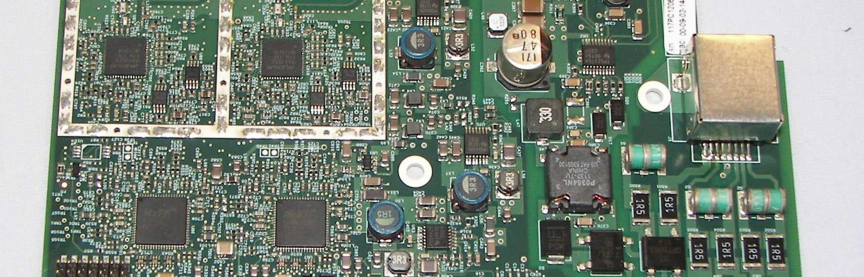
QC8-RDL3000RMA
Jul 17, 2012Advanced Broadband Wireless Infrastructure Solution
Equipment Class
TNB - Licensed Non-Broadcast Station Transmitter