QC8-AN50Access Node
Redline Communications Inc.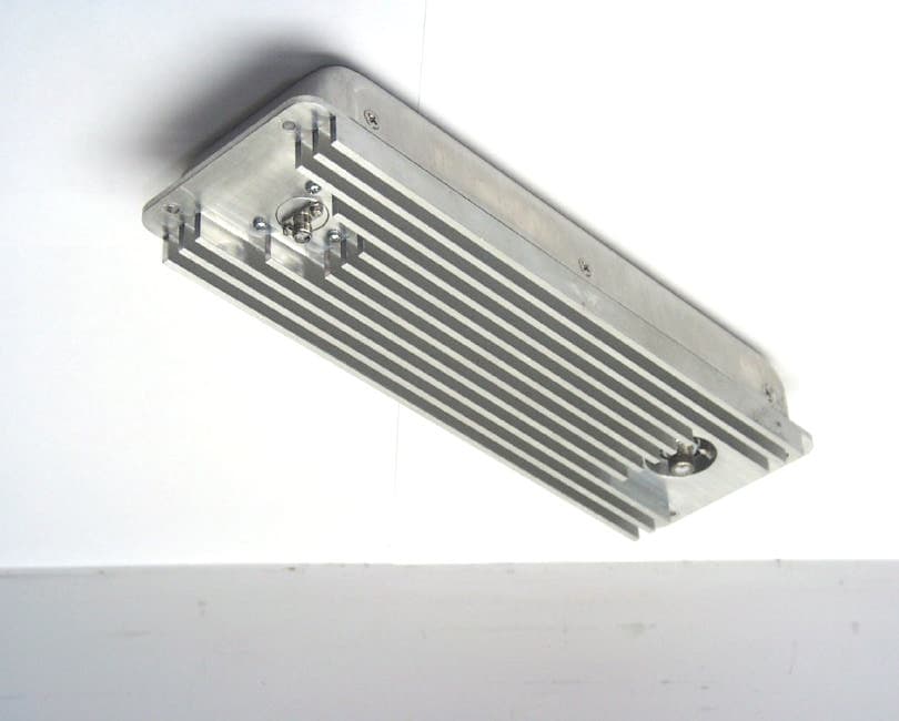
Click to zoom
Application Details
- Equipment Class
- NII - Unlicensed National Information Infrastructure TX
- Date of Grant
- Jul 01, 2002
- Application Purpose
- Original Equipment
- Date of Application
- Jul 01, 2002
- Equipment Note
- Access Node
- Frequency Range
- 5735.00000000 - 5815.00000000
- Company
- Redline Communications Inc.
- Country
- Canada
Documents & Files
Document Text
Text extracted from the exhibit documents filed with the FCC. Open a document above to read the original.
Users Manual
Guide USER Access Node-50 Redline Communications Inc. 90 Tiverton Court Suite 102 Markham, Ontario Canada L3R 9V2 ACCESS NODE - 50 USER GUIDE AN-50 User Manual 2/52 Redline Communications .....solving the first mile challenge. Redline Access Node-50 Guide USER Version 19 Copyright Information This document may not in whole or in part be copied, reproduced, or reduced to any medium without prior consent, in writing, from Redline Communications. Disclaimer This user guide was designed to help you install, use and troubleshoot the Redline AN-50 Fixed Wireless Access (FWA) PTP system. Every effort has been made to ensure the accuracy of the material provided herein, however, Redline assumes no responsibility regarding the use of the material. Additionally, Redline makes no representations or warranties, either expressed or implied, regarding the contents of this product. Redline Communications shall not be liable for any misuse regarding this product. If you have any comments or suggestions concerning this guide, please Email them to: [email protected]. AN-50 User Manual 3/52 Redline Communications .....solving the first mile challenge. TABLE OF CONTENTS 1. Getting Started........................................................................................................5 2. Important Safety Information..................................................................................6 3. Important Service Information.................................................................................7 4. Unpacking the AN-50 System.................................................................................8 4.1. The AN-50 Terminal at a Glance.....................................................................8 4.2. The AN-50 Transceiver/Antenna at a Glance.................................................11 5. AN-50 Terminal Installation..................................................................................12 5.1. General Site Survey.......................................................................................12 5.2. Installing the Antenna....................................................................................14 5.3. Running the IF Cable.....................................................................................16 5.4. Install the Terminal........................................................................................17 6. System Configuration and Operation.....................................................................20 6.1. Home Page Screen.........................................................................................20 6.2. Bridge Status Screen......................................................................................22 6.3. Configuration.................................................................................................24 6.4. Upgrade.........................................................................................................28 6.5. Change Password...........................................................................................29 6.6. Log File.........................................................................................................30 7. Diagnostics and Troubleshooting...........................................................................32 7.1. Diagnostics via the front panel.......................................................................32 7.1.1. System Power........................................................................................33 7.1.2. System Fault..........................................................................................33 7.1.3. Wireless Link.........................................................................................33 7.1.4. Wireless Signal......................................................................................34 7.1.5. Ethernet Link.........................................................................................34 7.1.6. Ethernet Collision..................................................................................35 7.2. Troubleshooting via the screen menu.............................................................35 7.2.1. Home page does not appear....................................................................35 8. Fixed Wireless Access Primer...............................................................................37 8.1. Introduction...................................................................................................37 8.2. Who can benefit from the AN-50?.................................................................37 8.3. The UNII band advantage..............................................................................39 8.4. Wireless Facts................................................................................................41 8.4.1. Link Budget...........................................................................................41 8.5. Deployment Scenarios...................................................................................47 8.5.1. Co-located deployments.........................................................................48 8.5.2. Adjacent area deployments.....................................................................48 9. AN-50 Specifications............................................................................................52 AN-50 User Manual 4/52 Redline Communications .....solving the first mile challenge. LIST OF FIGURES Figure 1 The AN-50 System out of the box.....................................................................8 Figure 2 Antenna/Transceiver close up..........................................................................11 Figure 3 AN-50 installation...........................................................................................12 Figure 4 Antenna deployment options.........................................................................…
Text truncated - open the document above for the full version.
Users Manual
AN-50 User Manual 26/52 Redline Communications .....solving the first mile challenge. Wireless Configuration: Channel: specifies the operating channel of the system, within the 100 MHz available in the 5.8GHz UNII band. The table below specifies the center frequencies of each permitted channel. Channel Frequency 1 5735 MHz 1A 5745 MHz 2 5755 MHz 2A 5765 MHz 3 5775 MHz 3A 5785 MHz 4 5795 MHz 4A 5805 MHz 5 5815 MHz To avoid interference, two PTP links operating in the same physical location (co-located) or within close proximity (e.g. across the street) must be separated by at least one channel, i.e. the gap between channels should be 20 MHz or more (e.g. channels 1 and 3). Refer to Section 8.5 for further information regarding deployment rules. Tx Power: this parameter specifies the power level of the system, which is preset at the factory and should not be altered. In the event that this parameter needs to be changed, please contact the Redline support team at [email protected] . Adaptive rate: checking this box sets the system to operate in adaptive modulation mode. It is recommended to keep the AN-50 in this mode so that the system can automatically adjust the modulation level to the highest possible data rate based on measured RF performance. The user can define the minimum desired modulation level by setting the Main rate parameter (see next item). If the system meets this data rate, then the “Signal” LED on the front panel will light continuously green. If packet errors exceed one out of a million, then the system will automatically lower the modulation level to maintain the link. In this case, the LED will flash green. If errors continue when the system reaches the lowest modulation level, then the LED will flash red to indicate a failed RF link. The user can also disable the dynamic modulation mode by unchecking the Adaptive rate box. In this mode, the user is required to set the Main rate and the Rate diff (see below). Refer to Table 1 to determine which modulation level can be used based on the measured signal to noise ratio. AN-50 User Manual 27/52 Redline Communications .....solving the first mile challenge. It is recommended not to operate the system in manual mode, as this mode is intended primarily for field support. Note the “Signal” LED will light solid green when the packet error rate is less than 1 out of a million. When the errors exceed this limit, the LED will not illuminate, indicating the RF link has failed. Main rate [Mb/s]: Defines the desired net data rate for the link. Rate dif.: applies when the Adaptive rate is disabled. Rate dif specifies how many levels the system must drop in modulation before beginning re- transmission to address packet errors. The Rate diff value can be set from 1-7, with 2 being the typical value. Master: Sets the AN-50 system to serve as the Master system, while the other AN-50 assumes a slave role. Version: Specifies the current version of the system software. Note, software can be remotely downloaded into the AN-50. The system comprises sufficient memory to hold two independent software loads – the operator can specify which load to download into the system. Peak Transmitted Power per channel and modulation The maximum conducted power is limited by the software / firmware to limit the maximum power for each channel. According to the rating showed in the following table based on direct measurements the maximum power for each channel isn’t user modifiable: PEAK TRANSMIT POWER (Measured a Peak Power Meter) (dBm) Transmitted Channel Frequency (MHz) 64QAM (54 Mb/s) 16QAM (36 Mb/s) QPSK (18 Mb/s) BPSK (9 Mb/s) 1 5.735 -7.4 -7.4 -7.4 -7.4 1A 5.745 16.6 16.6 16.6 16.6 2 5.755 17.3 17.3 17.3 17.3 2A 5.765 20.0 20.0 20.0 20.0 3 5.775 20.5 20.5 20.5 20.5 3A 5.785 20.0 20.0 20.0 20.0 4 5.795 17.3 17.3 17.3 17.3 4A 5.805 16.6 16.6 16.6 16.6 5 5.815 -7.4 -7.4 -7.4 -7.4 AN-50 User Manual 28/52 Redline Communications .....solving the first mile challenge. 6.4. Upgrade The upgrade screen, shown in Figure 16, is used to upgrade the existing software load of the AN-50 unit with new software stored in a binary file on the server or host computer. The system uses the Trivial File Transfer Protocol (TFTP) to execute the process. Two input fields have to be filled in by the operator: TFTP Server IP Address and File name. The TFTP Server IP Address is the IP address of the host computer or server that contains the upgraded software in binary format, while File name is the name of the actual binary file. Figure 16 Upgrade screen. After typing the TFTP Server IP Address and File name, press Upload to begin the file transfer. A status screen (see Figure 17) will immediately follow, which displays, in real-time, the number of bytes being transferred from the host computer/server to the AN-50 unit. The upgrade file size is approximately 1 Megabyte, and can take approximately 1-2 minutes to download from the server to the AN-50 memory. Note the AN-50 contains two memory pages for storing the software/firmware binary code images. One memory location holds the current software, while the second memory area is used to store the new software load. Upon successful transfer of the upgrade file, the AN-50 will verify the integrity of the new software load before transitioning its system to the new binary image. If errors were introduced during the transfer process, as a result of say link degradation, then the AN-50 will reject the new software load, and provide a warning that the upgrade was unsuccessful. In this case, the operator will need to repeat the upgrade process. As mentioned previously, the upgrade process can be achieved remotely, using HTTP over the Internet. AN-50 User Manual 29/52 Redline Communications .....solving the first mile challenge. Figure 17 Status of upgrade file transfer. 6.5. Change Password The default password for the system, set from the factory, is ‘admin’. To change the password, click on Change password from the main men…
Text truncated - open the document above for the full version.
Users Manual
AN-50 User Manual 12/51 Redline Communications .....solving the first mile challenge. 5. AN-50 Terminal Installation This section describes the easy steps to follow to install the AN-50 terminal and associated equipment. Figure 3 illustrates the three primary cables that are required to complete the installation including; Power, IF and CAT 5 (not included). The power cord connects to a standard North American 120 VAC power outlet, the IF cable connects the terminal (located indoors) to the transceiver (located outdoors), and the CAT 5 which connects the terminal to a switch or router for interface to the core network. Terminal CAT 5 Cable AC Power Chord IF Cable Transceiver Antenna Pole and Mount Flat Plate Antenna Figure 3 AN-50 installation. The terminal is for indoor installation only while the transceiver and antenna are mounted externally. The principal steps in installation are: 1. Conduct a general site survey 2. Install the antenna 3. Run the IF cable 4. Install the terminal Each step is addressed in more detail below. 5.1. General Site Survey The first step in installing the AN-50 system is to conduct a general site survey. Although the installation steps are relatively straightforward, they do involve some construction and electrical work, which can be best performed by professional installers. AN-50 User Manual 13/51 Redline Communications .....solving the first mile challenge. The following site survey steps should be followed: Determine the optimum location: The first key step in the deployment exercise is to determine and identify building candidates that can be used to support the PTP link. A critical parameter to consider is the range at which the two terminals are required to operate. Range performance is determined by empirical formulas that consider a number of equipment and environmental factors described in Section 8 of this manual. Ensure that the installation sites meet the above range performance requirements before moving to the next step. There are a number of cell planning tools available in the market today, which make use of topographic data to help with the cell planning. Obtain a copy of the facility blueprints and verify their accuracy. The installation process will require penetrating the building to run the IF cable between the outdoor and indoor units. In this regard, it is imperative that the blueprints of the building are up to date and accurate. Identify a Clear Line of Sight Path. For maximum performance, it is recommended to mount the antenna in a location where there is line of sight to the remote terminal. If possible, the antenna should be positioned such that there is maximum clearance within the first Fresnel zone of the direct path. Refer to Section 8 for a full description of Fresel zone clearance and its impact on signal propagation. The best means of achieving Fresnel zone clearance is to mount the antennas as high as possible, on either a tall building or tower, as shown in Figure 4. Although the system is designed to operate in obstructed line of sight (NLOS) conditions, as a result of the OFDM technology it incorporates, LOS deployments provide much greater throughput capability. AN-50 User Manual 14/51 Redline Communications .....solving the first mile challenge. Transceiver Deployments Figure 4 Antenna deployment options. Identify potential sources of RF interference. Measure for any possible RF interference on the roof-top or tower by utilizing a RF power meter or spectrum analyzer. RF interference arises from any other wireless system operating within the same frequency band of the AN-50. Note that the AN-50 can operate in any one of the four channels designated for UNII band, therefore, there is some flexibility in addressing or avoiding the interference should other transmitters, in relatively close proximity, pose a problem. Verify the location of access points. With the remote terminal transmitting, use a spectrum analyzer to ensure there is adequate signal strength arriving at the candidate location for the antenna. 5.2. Installing the Antenna Once the site survey has been completed, and the exact location of the antenna identified, the next step is to mount the AN-50 transceiver/antenna onto either a building structure or pole. The antenna and mounting brackets have been designed to withstand strong winds (see specifications at the end of this user guide). It is imperative that all bolts and nuts are securely fastened to avoid any movement that could introduce misalignment. Note that there is an arrow on the back of the antenna, which must be pointing upwards to indicate proper orientation when the antenna is deployed. AN-50 User Manual 15/51 Redline Communications .....solving the first mile challenge. Orientation Arrow For building mounts, ensure the surface to which the mounting bracket will be attached is flat and vertical (use a level). Install the bracket using four lag screws, with washers. There are two center holes that can be used to mount the bracket onto a 2x4 stud. Make sure the surface to which the bracket is attaching is structurally sound and can withstand the specified wind loading. Lag Screw and Washer Figure 5 Mounting the antenna on a building structure. Once the antenna is mounted, it has to be aligned in both the azimuth and elevation planes. The elevation alignment is accomplished by loosening the two bolts attached to the mounting bracket, as shown in Figure 6, and slanting the pole until the antenna is aligned in elevation towards the remote terminal. The azimuth alignment is achieved by loosening the two bolts on the antenna bracket, and rotating the antenna until alignment is achieved. AN-50 User Manual 16/51 Redline Communications .....solving the first mile challenge. Elevation Adjustment Adjustment Bolts Azimuth Adjustment Figure 6 Aligning the antenna. Note that the antenna can also be mounted onto another pole separate from the one supplied with the system. Contact Redline for different antenna…
Text truncated - open the document above for the full version.
External Photos
ANNEX 3 - EXTERNAL PHOTOS OF THE EQUIPMENT UNDER TESTPhoto # 1 ACCESS NODE (5.735-5.815 GHz), Model AN-50FCC ID: QC8-AN50 ANNEX 3 - EXTERNAL PHOTOS OF THE EQUIPMENT UNDER TESTPhoto # 2 ACCESS NODE (5.735-5.815 GHz), Model AN-50FCC ID: QC8-AN50 ANNEX 3 - EXTERNAL PHOTOS OF THE EQUIPMENT UNDER TESTPhoto # 3 ACCESS NODE (5.735-5.815 GHz), Model AN-50FCC ID: QC8-AN50 ANNEX 3 - EXTERNAL PHOTOS OF THE EQUIPMENT UNDER TESTPhoto # 4 ACCESS NODE (5.735-5.815 GHz), Model AN-50FCC ID: QC8-AN50 ANNEX 3 - EXTERNAL PHOTOS OF THE EQUIPMENT UNDER TESTPhoto # 5 ACCESS NODE (5.735-5.815 GHz), Model AN-50FCC ID: QC8-AN50 ANNEX 3 - EXTERNAL PHOTOS OF THE EQUIPMENT UNDER TESTPhoto # 6 ACCESS NODE (5.735-5.815 GHz), Model AN-50FCC ID: QC8-AN50 ANNEX 3 - EXTERNAL PHOTOS OF THE EQUIPMENT UNDER TESTPhoto # 7 ACCESS NODE (5.735-5.815 GHz), Model AN-50FCC ID: QC8-AN50 ANNEX 3 - EXTERNAL PHOTOS OF THE EQUIPMENT UNDER TESTPhoto # 8 ACCESS NODE (5.735-5.815 GHz), Model AN-50FCC ID: QC8-AN50 ANNEX 3 - EXTERNAL PHOTOS OF THE EQUIPMENT UNDER TESTPhoto # 9 ACCESS NODE (5.735-5.815 GHz), Model AN-50FCC ID: QC8-AN50 ANNEX 3 - EXTERNAL PHOTOS OF THE EQUIPMENT UNDER TESTPhoto # 10 ACCESS NODE (5.735-5.815 GHz), Model AN-50FCC ID: QC8-AN50
Internal Photos
ANNEX 4 - INTERNAL PHOTOS OF THE EQUIPMENT UNDER TESTPhoto # 1 ACCESS NODE (5.735-5.815 GHz), Model AN-50FCC ID: QC8-AN50 ANNEX 4 - INTERNAL PHOTOS OF THE EQUIPMENT UNDER TESTPhoto # 2 ACCESS NODE (5.735-5.815 GHz), Model AN-50FCC ID: QC8-AN50 ANNEX 4 - INTERNAL PHOTOS OF THE EQUIPMENT UNDER TESTPhoto # 3 ACCESS NODE (5.735-5.815 GHz), Model AN-50FCC ID: QC8-AN50 ANNEX 4 - INTERNAL PHOTOS OF THE EQUIPMENT UNDER TESTPhoto # 4 ACCESS NODE (5.735-5.815 GHz), Model AN-50FCC ID: QC8-AN50 ANNEX 4 - INTERNAL PHOTOS OF THE EQUIPMENT UNDER TESTPhoto # 5 ACCESS NODE (5.735-5.815 GHz), Model AN-50FCC ID: QC8-AN50 ANNEX 4 - INTERNAL PHOTOS OF THE EQUIPMENT UNDER TESTPhoto # 6 ACCESS NODE (5.735-5.815 GHz), Model AN-50FCC ID: QC8-AN50 ANNEX 4 - INTERNAL PHOTOS OF THE EQUIPMENT UNDER TESTPhoto # 7 ACCESS NODE (5.735-5.815 GHz), Model AN-50FCC ID: QC8-AN50 ANNEX 4 - INTERNAL PHOTOS OF THE EQUIPMENT UNDER TESTPhoto # 8 ACCESS NODE (5.735-5.815 GHz), Model AN-50FCC ID: QC8-AN50 ANNEX 4 - INTERNAL PHOTOS OF THE EQUIPMENT UNDER TESTPhoto # 9 ACCESS NODE (5.735-5.815 GHz), Model AN-50FCC ID: QC8-AN50 ANNEX 4 - INTERNAL PHOTOS OF THE EQUIPMENT UNDER TESTPhoto # 10 ACCESS NODE (5.735-5.815 GHz), Model AN-50FCC ID: QC8-AN50 ANNEX 4 - INTERNAL PHOTOS OF THE EQUIPMENT UNDER TESTPhoto # 11 ACCESS NODE (5.735-5.815 GHz), Model AN-50FCC ID: QC8-AN50 ANNEX 4 - INTERNAL PHOTOS OF THE EQUIPMENT UNDER TESTPhoto # 12 ACCESS NODE (5.735-5.815 GHz), Model AN-50FCC ID: QC8-AN50 ANNEX 4 - INTERNAL PHOTOS OF THE EQUIPMENT UNDER TESTPhoto # 13 ACCESS NODE (5.735-5.815 GHz), Model AN-50FCC ID: QC8-AN50 ANNEX 4 - INTERNAL PHOTOS OF THE EQUIPMENT UNDER TESTPhoto # 14 ACCESS NODE (5.735-5.815 GHz), Model AN-50FCC ID: QC8-AN50 ANNEX 4 - INTERNAL PHOTOS OF THE EQUIPMENT UNDER TESTPhoto # 15 ACCESS NODE (5.735-5.815 GHz), Model AN-50FCC ID: QC8-AN50 ANNEX 4 - INTERNAL PHOTOS OF THE EQUIPMENT UNDER TESTPhoto # 16 ACCESS NODE (5.735-5.815 GHz), Model AN-50FCC ID: QC8-AN50
Internal Photos
ANNEX 4 - INTERNAL PHOTOS OF THE EQUIPMENT UNDER TEST ACCESS NODE (5.735-5.815 GHz), Model AN-50FCC ID: QC8-AN50 Plot 1(a) - Zoom in Photos of Outdoor AN-50 Unit (1 st half of pcb) - Top view ANNEX 4 - INTERNAL PHOTOS OF THE EQUIPMENT UNDER TEST ACCESS NODE (5.735-5.815 GHz), Model AN-50FCC ID: QC8-AN50 Plot 1(b) - Zoom in Photos of Outdoor AN-50 Unit (2 nd half of pcb) - Top View ANNEX 4 - INTERNAL PHOTOS OF THE EQUIPMENT UNDER TEST ACCESS NODE (5.735-5.815 GHz), Model AN-50FCC ID: QC8-AN50 Plot 2(a) - Zoom in Photos of Outdoor AN-50 Unit (1 st half of pcb) - Back View ANNEX 4 - INTERNAL PHOTOS OF THE EQUIPMENT UNDER TEST ACCESS NODE (5.735-5.815 GHz), Model AN-50FCC ID: QC8-AN50 Plot 2(b) - Zoom in Photos of Outdoor AN-50 Unit (2 nd half of pcb) - Back View
Parts List/Tune Up Info
The Alignment Procedures for AN-50 System The AN-50 system includes two main units, which require alignments. These units are: AN-50 Terminal, also called AN50 and Transceiver, also called T58. We will refer to these units as they appear in the production test procedure: AN50 for Terminal and T58 for Transceiver. AN50 and T58 do not require tuning, but only level adjustments and frequency alignment. Each AN50 and T58 is checked and adjusted separately in production. The units sent at Ultratech for FCC testing have been adjusted using the same procedure, reference levels and traces. The following two items are part of the test procedure applied to each AN50: 1. TX-IF Test and Gain Adjustment We connect the AN50 through a reference (measured) cable to a spectrum analyzer as shown in figure 1. We load, into the spectrum analyzer, the reference trace and settings used to test and adjust the 815 MHz IF transmitter chain in AN50. We configure the AN50 to continuous transmission and we adjust potentiometer P1 until the transmit level measured by the spectrum analyzer matches a reference power level. This ensures that all AN50 units will have the same gain in the transmit chain. We also verify that the displayed spectrum matches the reference trace. This ensures that all AN50 units will have the same spectral output. AN50FTC2TG3TC1 Advantest R3162 NFSMN ETC PC1ETH ETH ETH 110VAC BAR PSC 110V 192.168.25.2 PIF H14JMP Figure1. Test Set-up for TX-IF Gain and Low IF-LO Frequency Adjustment 2. Low IF-LO Test and Frequency Adjustment With the same test set-up as in figure 1, we load, into the spectrum analyzer, the reference trace and settings used to verify the level and adjust the frequency offset for the Low IF-LO local oscillator. We adjust potentiometer P5 until the frequency offset of the system (measured at the 2.5GHz local oscillator frequency) matches the offset of the spectrum analyzer. This ensures an excellent frequency precision of the system. We also check that the LO has no spurs and the level matches the reference trace. The following item is part of the test procedure applied to each T58 (Transceiver): 1. TX-RF Test and Gain Adjustment We connect the T58 with a reference cable to a reference AN50 and with another reference cable to a spectrum analyzer as shown in figure 2. We load, into the spectrum analyzer, the reference trace and settings to test and adjust the TX-RF transmitter chain in T58 (Transceiver unit). We configure the AN50 to continuous transmission, on the channel 4 (one of the central channels) and we adjust potentiometer P4 until the transmit level measured by the spectrum analyzer matches a reference power level. This ensures that all units will have the same gain in the transmit chain. We also verify that the displayed spectrum matches the reference trace. This ensures that units will have similar spectral output. Note that we have different maximum power limits for different channels, and these limits are ensured automatically by the software via a digital control. Therefore, the linearity and the precision of the gain control are guaranteed by design. The maximum transmitted power is limited for each channel by software / firmware, according to the rating shows in the User’s Manual. The operator cannot change or exceed the minimum or maximum power limits. Reference AN50 F2h RG6T58FSMA ETC PC1ETH ETH ETH 110VAC BAR PSC 110V 192.168.25.3 H14JMP PIF TC1 Advantest R3162 NFSMN PIS Figure 2. Test Set-up for TX-RF Gain Adjustment
RF Exposure Info
AN-50 User Manual 12/52 Redline Communications .....solving the first mile challenge. 5. AN-50 Terminal Installation This section describes the easy steps to follow to install the AN-50 terminal and associated equipment. A Class A digital device that is marketed for use in a commercial, industrial or business environment. Figure 3 illustrates the three primary cables that are required to complete the installation including; Power, IF and CAT 5 (not included). The power cord connects to a standard North American 120 VAC power outlet, the IF cable connects the terminal (located indoors) to the transceiver (located outdoors), and the CAT 5 which connects the terminal to a switch or router for interface to the core network. Terminal CAT 5 Cable AC Power Chord IF Cable Transceiver Antenna Pole and Mount Flat Plate Antenna Figure 3 AN-50 installation. The terminal is for indoor installation only while the transceiver and antenna are mounted externally. The principal steps in installation are: 1. Conduct a general site survey 2. Install the antenna 3. Run the IF cable 4. Install the terminal Each step is addressed in more detail below. 5.1. General Site Survey The first step in installing the AN-50 system is to conduct a general site survey. Although the installation steps are relatively straightforward, they do involve AN-50 User Manual 13/52 Redline Communications .....solving the first mile challenge. some construction and electrical work, which can be best performed by professional installers. The following site survey steps should be followed: Determine the optimum location: The first key step in the deployment exercise is to determine and identify building candidates that can be used to support the PTP link. A critical parameter to consider is the range at which the two terminals are required to operate. Range performance is determined by empirical formulas that consider a number of equipment and environmental factors described in Section 8 of this manual. Ensure that the installation sites meet the above range performance requirements before moving to the next step. There are a number of cell planning tools available in the market today, which make use of topographic data to help with the cell planning. Obtain a copy of the facility blueprints and verify their accuracy. The installation process will require penetrating the building to run the IF cable between the outdoor and indoor units. In this regard, it is imperative that the blueprints of the building are up to date and accurate. Identify a Clear Line of Sight Path. For maximum performance, it is recommended to mount the antenna in a location where there is line of sight to the remote terminal. If possible, the antenna should be positioned such that there is maximum clearance within the first Fresnel zone of the direct path. Refer to Section 8 for a full description of Fresel zone clearance and its impact on signal propagation. The best means of achieving Fresnel zone clearance is to mount the antennas as high as possible, on either a tall building or tower, as shown in Figure 4. Although the system is designed to operate in obstructed line of sight (NLOS) conditions, as a result of the OFDM technology it incorporates, LOS deployments provide much greater throughput capability. AN-50 User Manual 14/52 Redline Communications .....solving the first mile challenge. Transceiver Deployments Figure 4 Antenna deployment options. Identify potential sources of RF interference. Measure for any possible RF interference on the roof-top or tower by utilizing a RF power meter or spectrum analyzer. RF interference arises from any other wireless system operating within the same frequency band of the AN-50. Note that the AN-50 can operate in any one of the four channels designated for UNII band, therefore, there is some flexibility in addressing or avoiding the interference should other transmitters, in relatively close proximity, pose a problem. Verify the location of access points. With the remote terminal transmitting, use a spectrum analyzer to ensure there is adequate signal strength arriving at the candidate location for the antenna. 5.2. Installing the Antenna Once the site survey has been completed, and the exact location of the antenna identified, the next step is to mount the AN-50 transceiver/antenna onto either a building structure or pole. The antenna and mounting brackets have been designed to withstand strong winds (see specifications at the end of this user guide). It is imperative that all bolts and nuts a…
Text truncated - open the document above for the full version.
Contact Information
Applicant
Mirza Wahaj(VP Engineering)
Test Firm
UltraTech Engineering Labs Inc.Tri Luu
Technical Specifications
| # | Rule Parts | Frequency Range | Power Output |
|---|---|---|---|
| 2 | 15E | 5.74 GHz - 5.82 GHz | 112.00 mW |
Other Applications from Redline Communications Inc.
QC8-RDL3000RMG
Dec 06, 2015Advanced Broadband Wireless Infrastructure Solution
Equipment Class
NII - Unlicensed National Information Infrastructure TXQC8-RDL3000RME
Jul 27, 2015Advanced Broadband Wireless Infrastructure Solution
Equipment Class
TNB - Licensed Non-Broadcast Station TransmitterQC8-RDL3000RMD
Dec 23, 2013Broadband wireless infrastructure product
Equipment Class
TNB - Licensed Non-Broadcast Station Transmitter
QC8-RDL3000RMF
Sep 04, 2013White Space Device with Geo-location - Fixed
Equipment Class
WGF - White Space Device with Geo-location- Fixed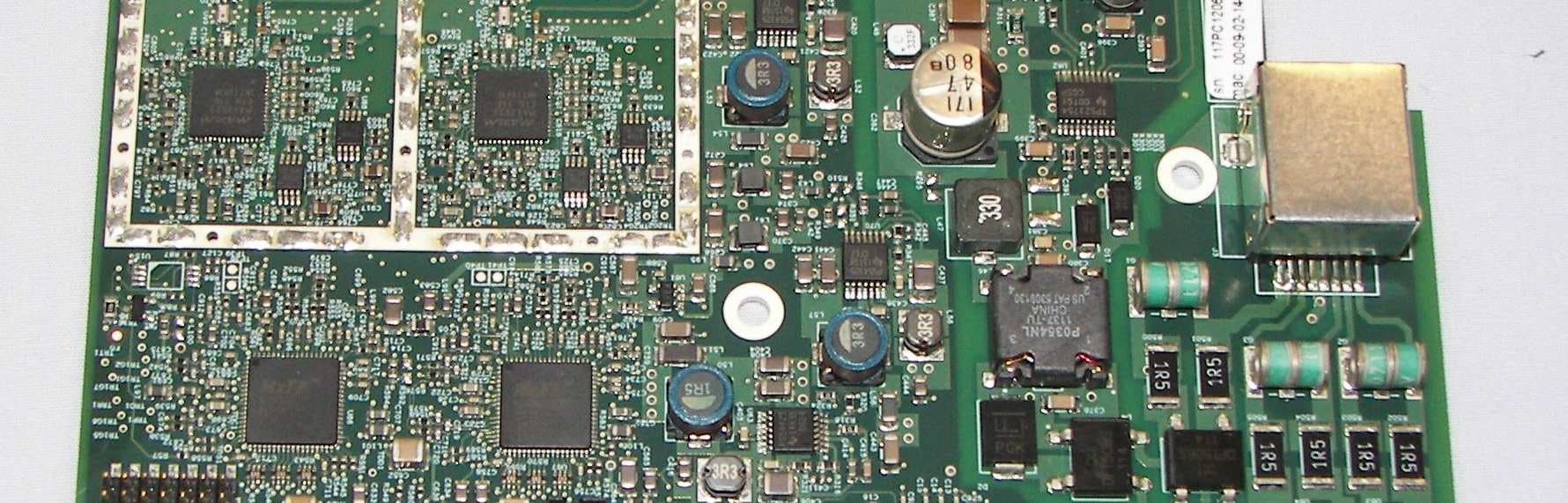
QC8-RDL3000RMA
Jul 17, 2012Advanced Broadband Wireless Infrastructure Solution
Equipment Class
TNB - Licensed Non-Broadcast Station Transmitter