QC8-AN5030EXAN-50e/AN-30e System w/ T-58e Radio
Redline Communications Inc.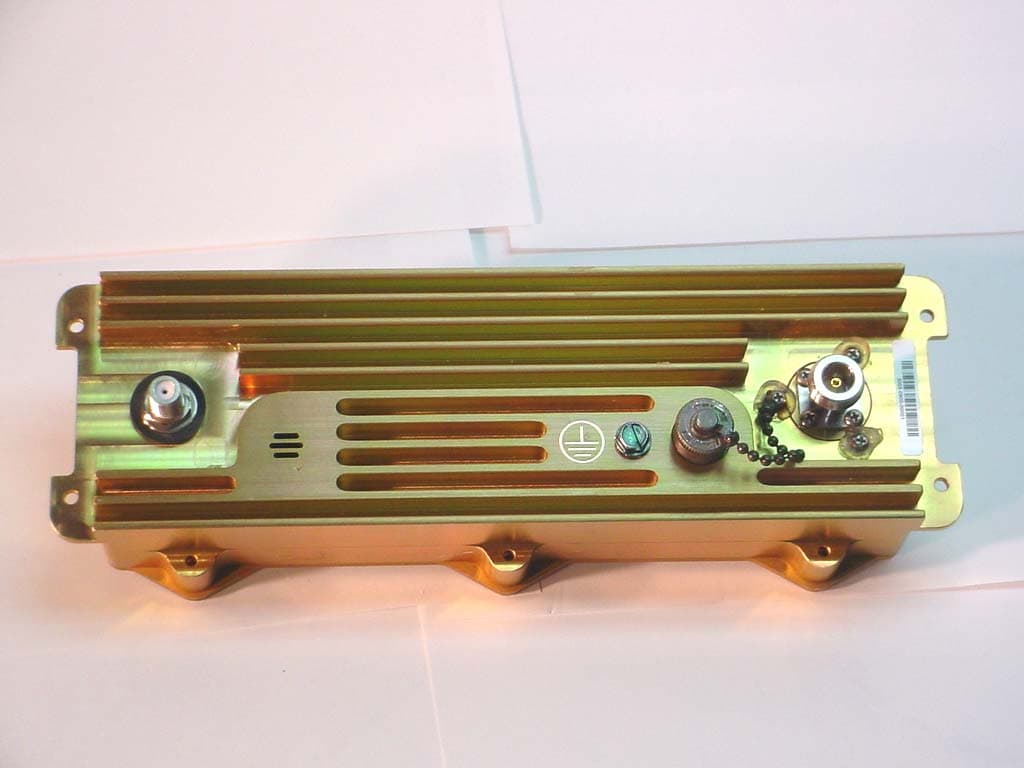
Click to zoom
Application Details
- Equipment Class
- DTS - Digital Transmission System
- Date of Grant
- Nov 23, 2004
- Application Purpose
- Original Equipment
- Date of Application
- Nov 23, 2004
- Equipment Note
- AN-50e/AN-30e System w/ T-58e Radio
- Frequency Range
- 5735.00000000 - 5840.00000000
- Company
- Redline Communications Inc.
- Country
- Canada
Documents & Files
Document Text
Text extracted from the exhibit documents filed with the FCC. Open a document above to read the original.
Users Manual
70-00035-01 Proprietary Redline Communications © 2004 November 2004 Page 1 of 104 AN-30e PTP System User Manual AN-30e user manual 70-00035-01 Proprietary Redline Communications © 2004 November 2004 Page 2 of 104 Copyright Information All rights reserved June 2004. The information in this document is proprietary to Redline Communications Inc. This document may not in whole or in part be copied, reproduced, or reduced to any medium without prior consent, in writing, from Redline Communications Incorporated. Copyright © 2004 Redline Communications Inc. Contact Information Redline Communications Inc. 302 Town Centre Blvd. Markham, ON Canada L3R 0E8 Web site: http://www.redlinecommunications.com Sales Inquiries: North American Toll-free sales line International [email protected] 1-866-633-6669 [email protected] Support: Email Telephone [email protected] Contact your Redline Distributor Product Registration http://www.redlinecommunications.com Click Support User ID: Register Password: Redline Disclaimer The statements, configurations, technical data, and recommendations in this document are believed to be accurate and reliable, but are presented without express or implied warranty. Additionally, Redline makes no representations or warranties, either expressed or implied, regarding the contents of this product. Redline Communications shall not be liable for any misuse regarding this product. The information in this document is subject to change without notice. 70-00035_01_AN_30e_UserMan-041111a.doc AN-30e user manual 70-00035-01 Proprietary Redline Communications © 2004 November 2004 Page 3 of 104 TABLE OF CONTENTS 1 Important Safety & Service Notices ....................................................... 9 1.1 Safety Warnings ........................................................................................ 9 1.2 Important Warning Symbols .................................................................... 10 1.3 Important Service Information ................................................................. 10 1.4 FCC Notice .............................................................................................. 11 1.5 UL Information ......................................................................................... 12 1.6 CE Notice ................................................................................................ 12 1.7 Lightning Protection................................................................................. 13 1.8 Product Information ................................................................................. 14 2 Getting Started....................................................................................... 15 2.1 Terms Used in this Manual ...................................................................... 16 3 System Overview................................................................................... 17 3.1 TDM over Wireless .................................................................................. 18 3.1.1 Theory of Operation............................................................................. 18 3.1.2 TDM Configuration .............................................................................. 18 4 Physical Description ............................................................................. 21 4.1 Quick Install Guide .................................................................................. 21 4.2 Unpacking the AN-30e ............................................................................ 21 4.3 AN-30e Terminal ..................................................................................... 22 4.3.1 Mounting .............................................................................................. 22 4.3.2 Power Supply ...................................................................................... 22 4.3.3 Time Synchronization Port .................................................................. 22 4.3.4 Wireless Section .................................................................................. 22 4.3.5 Ethernet Section .................................................................................. 24 4.3.6 System Section.................................................................................... 26 4.3.7 The TDM Interface............................................................................... 27 4.4 System Radio .......................................................................................... 29 4.4.1 Transceiver .......................................................................................... 29 4.4.2 IF Port (Radio Control) ........................................................................ 29 4.4.3 RF Connector ...................................................................................... 29 4.4.4 Alignment Pin and Audible Signal........................................................ 29 4.4.5 Antenna ............................................................................................... 29 4.4.6 Antenna Mounting Bracket .................................................................. 30 5 Using the Web Interface........................................................................ 31 5.1 System Menu........................................................................................... 31 5.2 General Information................................................................................. 33 5.2.1 System................................................................................................. 33 5.2.2 Ethernet: .............................................................................................. 34 5.2.3 Wireless: .............................................................................................. 34 5.3 System Status ......................................................................................... 35 5.3.1 …
Text truncated - open the document above for the full version.
Users Manual
70-00033-02 Proprietary Redline Communications © 2004 November 2004 Page 1 of 96 AN-50e System PTP / PMP User Manual AN-50e user manual 70-00033-02 Proprietary Redline Communications © 2004 November 2004 Page 2 of 96 Copyright Information All rights reserved March 2004 The information in this document is subject to change without notice. The statements, configurations, technical data, and recommendations in this document are believed to be accurate and reliable, but are presented without express or implied warranty. Users must take full responsibility for their applications of any products specified in this document. The information in this document is proprietary to Redline Communications Inc. This document may not in whole or in part be copied, reproduced, or reduced to any medium without prior consent, in writing, from Redline Communications Incorporated. Copyright © 2004 Redline Communications Inc. Contact Information Redline Communications Inc. 302 Town Centre Blvd. Markham, ON Canada L3R 0E8 Web site: http://www.redlinecommunications.com Sales Inquiries: North American Toll-free sales line International [email protected] 1-866-633-6669 [email protected] Support: Email Telephone [email protected] Contact your Redline Distributor Product Registration http://www.redlinecommunications.com Click 'Support' User ID: Register Password: Redline Disclaimer Every effort has been made to ensure the accuracy of the material provided herein; however, Redline assumes no responsibility regarding the use of the material. Additionally, Redline makes no representations or warranties, either expressed or implied, regarding the contents of this product. Redline Communications shall not be liable for any misuse regarding this product. 70-00033-01-AN_50e_UserMan-041111a.doc AN-50e user manual 70-00033-02 Proprietary Redline Communications © 2004 November 2004 Page 3 of 96 TABLE OF CONTENTS 1 Important Safety & Service Notices ....................................................... 7 1.1 Safety Warnings ........................................................................................ 7 1.2 Important Warning Symbols ...................................................................... 8 1.3 Important Service Information ................................................................... 8 1.4 FCC Notice ................................................................................................ 9 1.5 UL Information ......................................................................................... 10 1.6 CE Notice ................................................................................................ 10 1.7 Lightning Protection................................................................................. 11 1.8 Product Information ................................................................................. 12 2 Getting Started....................................................................................... 13 2.1 How To Use This Manual ........................................................................ 14 2.2 Terms Used in this Manual ...................................................................... 15 3 System Overview................................................................................... 16 4 Physical Description ............................................................................. 19 4.1 AN-50e Terminal ..................................................................................... 19 4.1.1 Mounting .............................................................................................. 19 4.1.2 Power Supply ...................................................................................... 19 4.1.3 Wireless Section .................................................................................. 19 4.1.4 Ethernet Section .................................................................................. 20 4.1.5 System Section.................................................................................... 21 4.1.6 Time Synchronization Port .................................................................. 23 4.1.7 Grounding Connection......................................................................... 23 4.2 Transceiver.............................................................................................. 23 4.3 Antenna ................................................................................................... 24 4.4 Mounting Bracket..................................................................................... 25 5 System Installation................................................................................ 27 5.1 Unpacking the AN-50e ............................................................................ 27 5.2 Site Planning ........................................................................................... 28 5.2.1 Master System Settings....................................................................... 29 5.2.2 Remote-end System Settings .............................................................. 30 5.3 General Site Survey ................................................................................ 31 5.3.1 Site Path Survey .................................................................................. 31 5.4 Install the AN-50e Terminal ..................................................................... 33 5.4.1 Mounting .............................................................................................. 33 5.4.2 Grounding ............................................................................................ 33 5.4.3 IF Cable ............................................................................................... 33 5.4.4 Power .................................................................................................. 34 5.4.5 Ethernet ......................................…
Text truncated - open the document above for the full version.
Cover Letter(s)
www.redlinecommunications.com 302 Town Centre Blvd., Markham, ON Canada L3R 0E8 Bus: 905.479.8344 Fax: 905.479.7432 November 16, 2004 FEDERAL COMMUNICATIONS COMMISSION 7435 Oakland Mills Road Columbia, MD 21046 U.S.A. Subject: Request for withholding from public disclosure the schematic diagrams and system block diagrams pursuant to an application for certification. Applicant: Redline Communications Inc. Product: Radio Transceiver Module Models: AN50e / AN30ewith transceiver T58e FCC ID: QC8-AN5030EX Dear Sir/Madam, We, Redline Communications, would like to request that the schematic diagrams, system block diagrams and technical description submitted with the application for certification be withheld from public disclosure as per Section 0.459 of FCC Rules. This request is made under the provisions of Section 0.457(d) of the Commission's Rules, and Section 552(b)(4) of the Freedom of Information Act. These sections authorize as a withholding from public inspection materials, which would be privileged as a matter of law if retained by the person submitting them, and materials which would not customarily be released to the public by that person. The detailed confidential materials are listed as follows: No. Title Drawing No. Sheet No. 1 Schematic Diagrams (all files) All Sheets 2 System Overview (all files) All Sheets 3 Bill of Materials (all files) All Sheets The AN50e and AN30e User Manuals are not confidential materials. Yours truly, Mihail Dobre Director of Engineering Services
External Photos
Annex 2 – External Photographs Photo # 13 5.8 GHz Radio Trasceiver Module, Model T58e FCC ID: QC8-AN5030EX IC: 4310A-AN5030EX Annex 2 – External Photographs Photo # 14 5.8 GHz Radio Trasceiver Module, Model T58e FCC ID: QC8-AN5030EX IC: 4310A-AN5030EX
External Photos
Annex 2 – External Photographs Photo # 1 AN-50e System, Models AN-50e & AN-30e FCC ID: QC8-AN5030EX IC: 4310A-AN5030EX Model AN-30e – Top View Annex 2 – External Photographs Photo # 2 AN-50e System, Models AN-50e & AN-30e FCC ID: QC8-AN5030EX IC: 4310A-AN5030EX Model AN-30e – Top View Annex 2 – External Photographs Photo # 3 AN-50e System, Models AN-50e & AN-30e FCC ID: QC8-AN5030EX IC: 4310A-AN5030EX Model AN-50e – Top View Annex 2 – External Photographs Photo # 4 AN-50e System, Models AN-50e & AN-30e FCC ID: QC8-AN5030EX IC: 4310A-AN5030EX Model AN-50e – Top View
ID Label/Location Info
Labels – AN50e, AN30e with transceiver T58e Page 1 of 2 11/16/2004 Labels – AN50e, AN30e with transceiver T58e Page 2 of 2 11/16/2004
ID Label/Location Info
Labels position Chassis label for AN50e IDU Chassis label for AN30e IDU Chassis label for T58e radio
Internal Photos
Annex 3 – Internal Photographs Photo # 16 5.8 GHz Radio Trasceiver Module, Model T58e FCC ID: QC8-AN5030EX IC: 4310A-AN5030EX Annex 3 – Internal Photographs Photo # 17 5.8 GHz Radio Trasceiver Module, Model T58e FCC ID: QC8-AN5030EX IC: 4310A-AN5030EX Annex 3 – Internal Photographs Photo # 18 5.8 GHz Radio Trasceiver Module, Model T58e FCC ID: QC8-AN5030EX IC: 4310A-AN5030EX Annex 3 – Internal Photographs Photo # 19 5.8 GHz Radio Trasceiver Module, Model T58e FCC ID: QC8-AN5030EX IC: 4310A-AN5030EX Annex 3 – Internal Photographs Photo # 20 5.8 GHz Radio Trasceiver Module, Model T58e FCC ID: QC8-AN5030EX IC: 4310A-AN5030EX
Internal Photos
Annex 3 – Internal Photographs Photo # 1 AN-50e System, Models AN-50e & AN-30e FCC ID: QC8-AN5030EX IC: 4310A-AN5030EX Model AN-30e – Top View Annex 3 – Internal Photographs Photo # 2 AN-50e System, Models AN-50e & AN-30e FCC ID: QC8-AN5030EX IC: 4310A-AN5030EX Model AN-50e – Top View Annex 3 – Internal Photographs Photo # 3 AN-50e System, Models AN-50e & AN-30e FCC ID: QC8-AN5030EX IC: 4310A-AN5030EX Model AN-50e / AN-30e with Dual AC Power Supplies Annex 3 – Internal Photographs Photo # 4 AN-50e System, Models AN-50e & AN-30e FCC ID: QC8-AN5030EX IC: 4310A-AN5030EX Model AN-50e / AN-30e with AC & DC Power Supplies Annex 3 – Internal Photographs Photo # 5 AN-50e System, Models AN-50e & AN-30e FCC ID: QC8-AN5030EX IC: 4310A-AN5030EX Model AN-50e / AN-30e with DC & DC Power Supplies Annex 3 – Internal Photographs Photo # 6 AN-50e System, Models AN-50e & AN-30e FCC ID: QC8-AN5030EX IC: 4310A-AN5030EX AC Power Supplies Annex 3 – Internal Photographs Photo # 7 AN-50e System, Models AN-50e & AN-30e FCC ID: QC8-AN5030EX IC: 4310A-AN5030EX AC Power Supplies Annex 3 – Internal Photographs Photo # 8 AN-50e System, Models AN-50e & AN-30e FCC ID: QC8-AN5030EX IC: 4310A-AN5030EX DC Power Supplies Annex 3 – Internal Photographs Photo # 9 AN-50e System, Models AN-50e & AN-30e FCC ID: QC8-AN5030EX IC: 4310A-AN5030EX DC Power Supplies Annex 3 – Internal Photographs Photo # 10 AN-50e System, Models AN-50e & AN-30e FCC ID: QC8-AN5030EX IC: 4310A-AN5030EX AN-50e / AN-30e Main Board Annex 3 – Internal Photographs Photo # 11 AN-50e System, Models AN-50e & AN-30e FCC ID: QC8-AN5030EX IC: 4310A-AN5030EX AN-50e / AN-30e Main Board Annex 3 – Internal Photographs Photo # 12 AN-50e System, Models AN-50e & AN-30e FCC ID: QC8-AN5030EX IC: 4310A-AN5030EX AN-50e / AN-30e Main Board Annex 3 – Internal Photographs Photo # 13 AN-50e System, Models AN-50e & AN-30e FCC ID: QC8-AN5030EX IC: 4310A-AN5030EX AN-50e / AN-30e Main Board (Radio Section) Annex 3 – Internal Photographs Photo # 14 AN-50e System, Models AN-50e & AN-30e FCC ID: QC8-AN5030EX IC: 4310A-AN5030EX T1/E1 Daughter Board (Only installed in Model AN-30e) Annex 3 – Internal Photographs Photo # 15 AN-50e System, Models AN-50e & AN-30e FCC ID: QC8-AN5030EX IC: 4310A-AN5030EX T1/E1 Daughter Board (Only installed in Model AN-30e)
RF Exposure Info
FCC PART 15, SUBPART C, SEC. 15.247 - INTENTIONAL RADIATORS Page 49 AN-50e/AN-30e SYSTEM, Model No: AN-50e and AN-30e with T-58e Trasceiver Module (5.8 GHz) FCC ID: QC8-AN5030EX ULTRATECH GROUP OF LABS File #: RCI-093-FCC15C 3000 Bristol Circle, Oakville, Ontario, Canada L6H 6G4 Oct. 07, 2004 Tel. : 905-829-1570, Fax. : 905-829-8050 All test results contained in this engineering test report are traceable to National Institute of Standards and Technology (NIST) 5.9. RF EXPOSURE REQUIRMENTS @ FCC 15.247(I), 1.1307(B)(1) 5.9.1. Limits FCC 15.247(i): Systems operating under provisions of this section shall be operated in a manner that ensures that the public is not exposed to radio frequency energy levels in excess of the Commission’s guidelines. See @ 1.1307(b)(1). FCC 1.1310:- The criteria listed in the following table shall be used to evaluate the environmental impact of human exposure to radio-frequency (RF) radiation as specified in 1.1307(b). LIMITS FOR MAXIMUM PERMISSIBLE EXPOSURE (MPE) Frequency Range (MHz) Electric Field Strength (V/m) Magnetic Field Strength (A/m) Power Density (mW/cm 2 ) Average Time (minutes) (A) Limits for Occupational/Control Exposures 1500-100,000 ... ... 5 6 (B) Limits for General Population/Uncontrolled Exposure 1500-100,000 ... ... 1.0 30 F = Frequency in MHz 5.9.2. Method of Measurements Refer to FCC @ 1.1310, 2.1091 • Spread spectrum transmitters operating under section 15.247 are categorically from routine environmental evaluation to demonstrating RF exposure compliance with respect to MPE and/or SAR limits. These devices are not exempted from compliance (As indicated in Section 15.247(b)(4), these transmitters are required to operate in a manner that ensures that exposure to public users and nearby persons) does not exceed the Commission’s RF exposure guidelines (see Section 1.1307 and 2.1093). Unless a device operates at substantially low power levels, with a low gain antenna(s), supporting information is generally needed to establish the various potential operating configurations and exposure conditions of a transmitter and its antenna(s) in order to determine compliance with the RF exposure guidelines. • In order to demonstrate compliance with MPE requirements (see Section 2.1091), the following information is typically needed: (1) Calculation that estimates the minimum separation distance (20 cm or more) between an antenna and persons required to satisfy power density limits defined for free space. (2) Antenna installation and device operating instructions for installers (professional/unskilled users), and the parties responsible for ensuring compliance with the RF exposure requirement (3) Any caution statements and/or warning labels that are necessary in order to comply with the exposure limits (4) Any other RF exposure related issues that may affect MPE compliance FCC PART 15, SUBPART C, SEC. 15.247 - INTENTIONAL RADIATORS Page 50 AN-50e/AN-30e SYSTEM, Model No: AN-50e and AN-30e with T-58e Trasceiver Module (5.8 GHz) FCC ID: QC8-AN5030EX ULTRATECH GROUP OF LABS File #: RCI-093-FCC15C 3000 Bristol Circle, Oakville, Ontario, Canada L6H 6G4 Oct. 07, 2004 Tel. : 905-829-1570, Fax. : 905-829-8050 All test results contained in this engineering test report are traceable to National Institute of Standards and Technology (NIST) Calculation Method of RF Safety Distance: S = PG/4Πr 2 =EIRP/4Πr 2 Where: P: power input to the antenna in mW EIRP: Equivalent (effective) isotropic radiated power. S: power density mW/cm 2 G: numeric gain of antenna relative to isotropic radiator r: distance to centre of radiation in cm FCC radio frequency exposure limits may be exceeded at distances closer than r cm from the antenna of this device r = PG/4ΠS FCC radio frequency exposure limits may not be exceeded at distances closer than r cm from the antenna of this device • For portable transmitters (see Section 2.1093), or devices designed to operate next to a person’s body, compliance is determined with respect to the SAR limit (define in the body tissues) for near-field exposure conditions. If the maximum average output power, operating condition configurations and exposure conditions are comparable to those of existing cellular and PCS phones., an SAR evaluation may be required in order to determine if such a device complies with SAR limit. When SAR evaluation data is not available, and the additional supporting information cannot assure compliance, the Commission may request that a SAR evaluation be performed, as provided for in Section 1.1307(d) FCC PART 15, SUBPART C, SEC. 15.247 - INTENTIONAL RADIATORS Page 51 AN-50e/AN-30e SYSTEM, Model No: AN-50e and AN-30e with T-58e Trasceiver Module (5.8 GHz) FCC ID: QC8-AN5030EX ULTRATECH GROUP OF LABS File #: RCI-093-FCC15C 3000 Bristol Circle, Oakville, Ontario, Canada L6H 6G4 Oct. 07, 2004 Tel. : 905-829-1570, Fax. : 905-829-8050 All test results contained in this engineering test report are traceable to National Institute of Standards and Technology (NIST) 5.9.3. Test Data 5.9.3.1. FOR POINT TO MULTIPOINT APPLICATION With any antenna, the maximum EIRP is allowed to be 36 dBm or 4,000 mili-Watts The minimum separation distance = 17.8 cm Note 1 : RF EXPOSURE DISTANCE LIMITS: r = (PG/4ΠS) 1/2 = (EIRP/4ΠS) 1/2 S = 1.0 mW/cm 2 5.9.3.2. FOR POINT TO POINT APPLICATION The maximum antenna gain is 34.6 dBi by using Radiowaves SP4-5-2NS Antenna, which allows the maximum EIRP of 60.77 dBm or 1.19 kWatts. The minimum separation distance = 308 cm Note 1 : RF EXPOSURE DISTANCE LIMITS: r = (PG/4ΠS) 1/2 = (EIRP/4ΠS) 1/2 S = 1.0 mW/cm 2 Evaluation of RF Exposure Compliance Requirements RF Exposure Requirements Compliance with FCC Rules Minimum calculated separation distance between antenna and persons required: • 17.8 centimeters for Point to MultiPoint application • 308 centimeters for Point to Point application. Manufacturer’ instruction for separation distance between antenna and persons required: • 20 cm for Point to Multipoint applica…
Text truncated - open the document above for the full version.
RF Exposure Info
AN-50e user manual 70-00033-02 Proprietary Redline Communications © 2004 November 2004 Page 9 of 96 1.4 FCC Notice 1. The System is used as a fixed wireless Ethernet bridge that requires professional installation with specified antennas and output power levels certified under the FCC Grant for System for point-to-point mode of operations. 2. FCC RF Exposure Requirements: T-54 and T-58: The antenna(s) used for these radios must be fixed-mounted on outdoor permanent structures. In point-to-point applications each antenna must be separated from all persons by a distance of at least 2.5 meters. In point-to- multipoint applications each antenna must be separated from all persons by a distance of at least 20 centimetres. T-58e: The antenna(s) used for this radio must be fixed-mounted on outdoor permanent structures. In point-to-point applications each antenna must be separated from all persons by a distance of at least 3.1 meters. In point-to- multipoint applications each antenna must be separated from all persons by a distance of at least 20 centimetres. 3. The System is certified by the FCC and Industry Canada with the 5.4/5.8 GHz directional and parabolic antennas listed in the Appendix of this manual. 4. For fixed, point-to-point mode of operations, the transmitting antennas must be directional as specified in this User Manual; the use of omni-directional antenna is prohibit for point-to-point operation. 5. For Class A Unintentional Radiators: This equipment has been tested and found to comply with the limits for a Class A digital device, pursuant to Part 15 of the FCC Rules. These limits are designed to provide reasonable protection against harmful interference when the equipment is operated in a commercial environment. This equipment generates, uses, and can radiate radio frequency energy and, if not installed and used in accordance with the instruction manual, may cause harmful interference to radio communications. Operation of this equipment in a residential area is likely to cause harmful interference in which case the user will be required to correct the interference at their own expense. 6. Warning : Changes or modifications not expressly approved by Redline Communications Inc. could void the user's authority to operate the equipment.
RF Exposure Info
AN-30e user manual 70-00035-01 Proprietary Redline Communications © 2004 November 2004 Page 11 of 104 1.4 FCC Notice 1. The System is used as a fixed wireless Ethernet bridge that requires professional installation with specified antennas and output power levels certified under the FCC Grant for System for point-to-point mode of operations. 2. FCC RF Exposure Requirements: T-54 and T-58: The antenna(s) used for these radios must be fixed-mounted on outdoor permanent structures. In point-to-point applications each antenna must be separated from all persons by a distance of at least 2.5 meters. In point-to- multipoint applications each antenna must be separated from all persons by a distance of at least 20 centimetres. T-58e: The antenna(s) used for this radio must be fixed-mounted on outdoor permanent structures. In point-to-point applications each antenna must be separated from all persons by a distance of at least 3.1 meters. In point-to- multipoint applications each antenna must be separated from all persons by a distance of at least 20 centimetres. 3. The System is certified by the FCC and Industry Canada with the 5.4/5.8 GHz directional and parabolic antennas listed in the Appendix of this manual. 4. For fixed, point-to-point mode of operations, the transmitting antennas must be directional as specified in this Users Manual; the use of omni-directional antenna is prohibit for point-to-point operation. 5. For Class A Unintentional Radiators: This equipment has been tested and found to comply with the limits for a Class A digital device, pursuant to Part 15 of the FCC Rules. These limits are designed to provide reasonable protection against harmful interference when the equipment is operated in a commercial environment. This equipment generates, uses, and can radiate radio frequency energy and, if not installed and used in accordance with the instruction manual, may cause harmful interference to radio communications. Operation of this equipment in a residential area is likely to cause harmful interference in which case the user will be required to correct the interference at their expense. 6. Warning : Changes or modifications not expressly approved by Redline Communications Inc. could void the authority of the user to operate the equipment.
Test Report
ENGINEERING TEST REPORT AN-50e/AN-30e SYSTEM Model No.: AN-50e and AN-30e with T-58e Trasceiver Module (5.8 GHz) FCC ID: QC8-AN5030EX Applicant: REDLINE COMMUNICATIONS INC. 302 Town Centre Blvd. Markham, Ontario Canada, L3R 0E8 In Accordance With FEDERAL COMMUNICATIONS COMMISSION (FCC) PART 15, SUBPART C, SEC. 15.247 Intentional Radiators operating in: 5.735-5.840 GHz UltraTech's File No.: RCI-093-FCC15C This Test report is Issued under the Authority of Tri M. Luu, Professional Engineer, Vice President of Engineering UltraTech Group of Labs Date: Oct. 07, 2004 Report Prepared by: Tri M. Luu Tested by: Hung Trinh, RFI Technician Issued Date: Oct. 07, 2004 Test Dates: Sept. 24 - Oct. 02, 2004 The results in this Test Report apply only to the sample(s) tested, and the sample tested is randomly selected. This report must not be used by the client to claim product endorsement by NVLAP or any agency of the US Government. UltraTech 3000 Bristol Circle, Oakville, Ontario, Canada, L6H 6G4 Tel.: (905) 829-1570 Fax.: (905) 829-8050 Website: www.ultratech-labs.com Email: [email protected], Email: [email protected] 2 31040/SIT C-1376 46390-2049 200093-0 SL2-IN-E-1119R 00-034 FCC PART 15, SUBPART C, SEC. 15.247 - INTENTIONAL RADIATORS Page 2 AN-50e/AN-30e SYSTEM, Model No: AN-50e and AN-30e with T-58e Trasceiver Module (5.8 GHz) FCC ID: QC8-AN5030EX ULTRATECH GROUP OF LABS File #: RCI-093-FCC15C 3000 Bristol Circle, Oakville, Ontario, Canada L6H 6G4 Oct. 07, 2004 Tel. : 905-829-1570, Fax. : 905-829-8050 All test results contained in this engineering test report are traceable to National Institute of Standards and Technology (NIST) TABLE OF CONTENTS EXHIBIT 1. INTRODUCTION .................................................................................................................................. 4 1.1. SCOPE..................................................................................................................…
Text truncated - open the document above for the full version.
Contact Information
Applicant
Mirza Wahaj(VP Engineering)
Test Firm
UltraTech Engineering Labs Inc.Tri Luu
Technical Specifications
| # | Rule Parts | Frequency Range | Power Output |
|---|---|---|---|
| 1 | 15C | 5.74 GHz - 5.84 GHz | 414.00 mW |
Other Applications from Redline Communications Inc.
QC8-RDL3000RMG
Dec 06, 2015Advanced Broadband Wireless Infrastructure Solution
Equipment Class
NII - Unlicensed National Information Infrastructure TXQC8-RDL3000RME
Jul 27, 2015Advanced Broadband Wireless Infrastructure Solution
Equipment Class
TNB - Licensed Non-Broadcast Station TransmitterQC8-RDL3000RMD
Dec 23, 2013Broadband wireless infrastructure product
Equipment Class
TNB - Licensed Non-Broadcast Station Transmitter
QC8-RDL3000RMF
Sep 04, 2013White Space Device with Geo-location - Fixed
Equipment Class
WGF - White Space Device with Geo-location- Fixed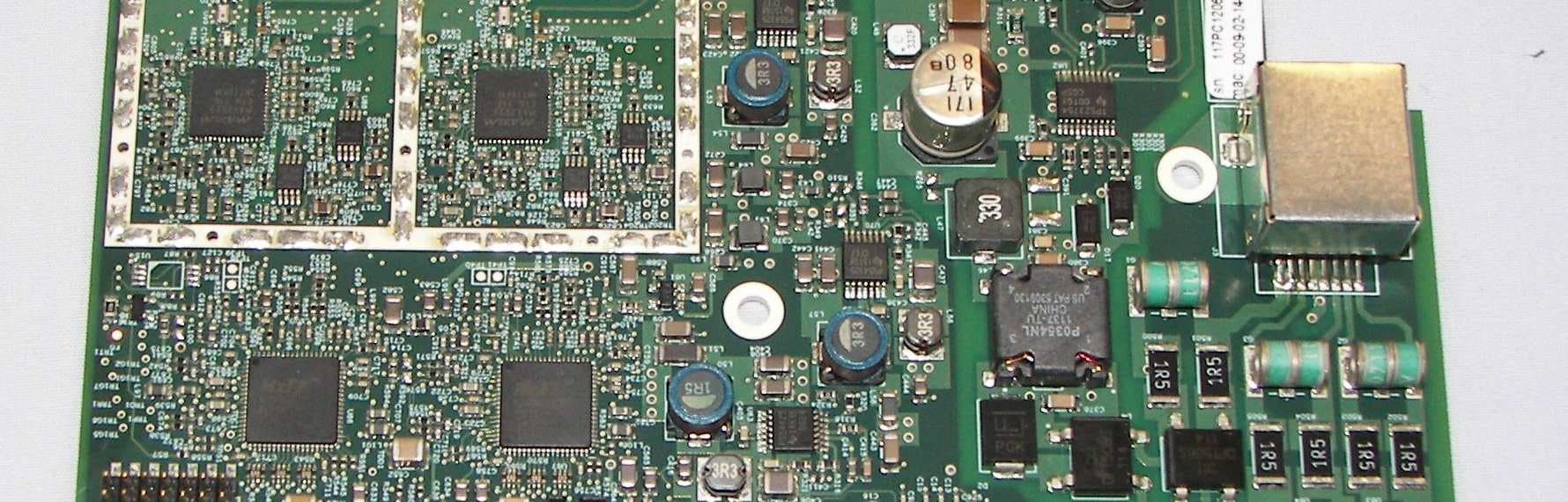
QC8-RDL3000RMA
Jul 17, 2012Advanced Broadband Wireless Infrastructure Solution
Equipment Class
TNB - Licensed Non-Broadcast Station Transmitter