QC8-AN80ICOFDM Broadband Wireless Transceiver
Redline Communications Inc.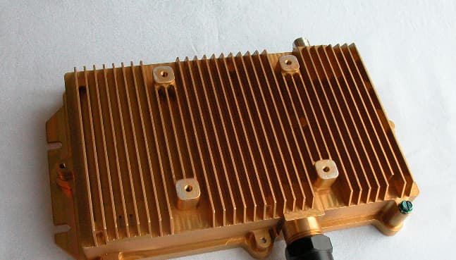
Click to zoom
Application Details
- Equipment Class
- TNB - Licensed Non-Broadcast Station Transmitter
- Date of Grant
- Feb 07, 2008
- Application Purpose
- Original Equipment
- Date of Application
- Feb 07, 2008
- Equipment Note
- OFDM Broadband Wireless Transceiver
- Frequency Range
- 4940.00000000 - 4990.00000000
- Company
- Redline Communications Inc.
- Country
- Canada
Documents & Files
Document Text
Text extracted from the exhibit documents filed with the FCC. Open a document above to read the original.
Users Manual
70-00072-01-05-DRAFT Proprietary Redline Communications © 2008 Page 1 of 94 January 22, 2008 RedCONNEX TM AN-80i PTP & PMP System User Manual RedCONNEX ™ User AN-80i Manual 70-00072-01-05-DRAFT Proprietary Redline Communications © 2008 Page 2 of 94 January 22, 2008 Copyright Information All rights reserved January 22, 2008. The information in this document is proprietary to Redline Communications Inc. This document may not in whole or in part be copied, reproduced, or reduced to any medium without prior consent, in writing, from Redline Communications Incorporated. Contact Information: Redline Communications Inc. 302 Town Centre Blvd. Suite 100 Markham, ON Canada L3R 0E8 Web site: http://www.redlinecommunications.com Sales Inquiries: North American [email protected] Toll-free sales 1-866-633-6669 International [email protected] Support: www.redlinecommunications.com/support/support_portal.html Document Control: 70-00072-01-05-AN-80i_User_Manual-20080122a.doc Disclaimer The statements, configurations, technical data, and recommendations in this document are believed to be accurate and reliable, but are presented without express or implied warranty. Additionally, Redline makes no representations or warranties, either expressed or implied, regarding the contents of this product. Redline Communications shall not be liable for any misuse regarding this product. The information in this document is subject to change without notice. RedCONNEX ™ User AN-80i Manual 70-00072-01-05-DRAFT Proprietary Redline Communications © 2008 Page 3 of 94 January 22, 2008 TABLE OF CONTENTS 1 Important Safety & Service Notices....................................................... 8 1.1 Safety Warnings ........................................................................................ 8 1.2 Important Warning Symbols ...................................................................... 9 1.3 Important Service Information ................................................................... 9 1.4 Lightning Protection................................................................................... 9 1.5 FCC & IC Notice ...................................................................................... 10 1.6 UL Information ......................................................................................... 11 1.7 Product Information ................................................................................. 11 2 System Overview................................................................................... 12 2.1 Ethernet Port ........................................................................................... 13 2.2 RF Port .................................................................................................... 13 2.3 Mounting Brackets................................................................................... 13 2.4 Grounding Connection ............................................................................ 13 2.5 Indoor Power Block (PoE Power Adapter) .............................................. 14 2.6 Antenna Alignment .................................................................................. 15 2.6.1 Web Page Alignment........................................................................... 15 2.6.2 Audible Alignment................................................................................ 15 3 Web Interface - PTP............................................................................... 16 3.1 System Login........................................................................................... 16 3.2 System Menu .......................................................................................... 17 3.3 System Information ................................................................................. 18 General................................................................................................ 18 Ethernet ............................................................................................... 19 Wireless............................................................................................... 19 3.4 System Status ......................................................................................... 20 General information ............................................................................. 20 Ethernet LAN Statistics ....................................................................... 21 Wireless Statistics ............................................................................... 21 Controls ............................................................................................... 21 3.5 System Logs Screen ............................................................................... 22 3.6 System Configuration Screen.................................................................. 25 Ethernet Configuration ........................................................................ 25 Wireless Configuration ........................................................................ 28 Controls ............................................................................................... 33 3.7 Users Management ................................................................................. 34 3.8 AN-80i Product Options Screen .............................................................. 36 3.9 Upload Software ...................................................................................... 37 3.10 SNMP Settings Screen............................................................................ 38 3.10.1 Change SNMP Community ................................................................. 39 3.10.2 Change SNMP Trap Configuration...................................................... 40 3.11 Spectrum Sweep ..................................................................................... 41 4 PMP Operation.......................................…
Text truncated - open the document above for the full version.
Cover Letter(s)
www.redlinecommunications.com 302 Town Centre Blvd., Suite 100, Markham, ON Canada, L3R 0E8 Bus: 905.479.8344 Fax: 905.479.7432 DATE: January 17, 2008 Equipment Authorization Division Federal Communications Commission 7435 Oakland Mills Road Columbia, MD 21046 FCC ID: QC8-AN80IC Product Name: AN-80i Request for Confidentiality Pursuant to Sections 0.457 and 0.459 of the commissions rules, we hereby request that the following documents be held confidential: ∑ Schematics_Digital ∑ Schematics_RF ∑ Bill of Materials_Digital ∑ Bill of Materials_RF ∑ Block diagram These materials contain trade secrets and proprietary information and are not customarily released to the public. The public disclosure of this information might be harmful to the company and provide unjustified benefits to our competitors. Medhat I. Fawzy, P.Eng Compliance Manager Tel. (905) 479-8344 x443 Fax. (905) 479-5331 e-mail: [email protected]
Operational Description
Product Overview AN-80i The Access Node 80i system is manufactured by Redline Communications -- a world leader in design and production of Broadband Fixed Wireless (BFW) systems. Figure 1: AN-80i System Components The AN-80i is a high-performance, high-speed wireless Ethernet bridge. The system operates in the 4.94-4.99 GHz, 5.15-5.35 GHz, 5.4-5.7 GHz and 5.8 GHz band and includes advanced technologies to address inter-cell interference. The system also delivers enhanced security through a proprietary over- the-air encryption scheme. The AN-80i can be equipped with a narrow beam antenna to provide high directivity for long-range operations over 50 miles (80 km) in clear line of sight (LOS) conditions. The AN-80i system is for use in a commercial, industrial or business environment.The system is equipped with an Automatic Transmitter Power Control (ATPC) function to automatically adjust transmission levels and achieve optimum performance. Each wireless link is comprised of two AN-80i units. One unit is configured for master mode and controls the wireless link; the master function is transparent to all Ethernet operations. The AN-80i system utilizes Redline's advanced Medium Access Control (MAC) design to provide efficient transmission of data. The AN-80i system uses time division duplexing (TDD) to transmit and receive on the same RF channel. The unit MB_AN-80i-Overview-DRAFT Proprietary Redline Communications © 2008 Page 1 of 3 Jan 28, 2008 AN-80i Product Overview designated 'master' uses a scheduled request/grant mechanism to arbitrate requests for bandwidth from the remote unit -- providing non contention-based traffic with predictable transmission characteristics. The AN-80i consists of an integrated outdoor unit with a selection of available external antennas, and an indoor PoE power injector that provides operational power for the AN-80i and connection to the Ethernet network. The AN-80i outdoor unit is housed in a weatherproof aluminum alloy case. Figure 2: Intro - AN-80i System with Integrated Antenna Ethernet Port The AN-80i auto-sensing 10/100Base-T Ethernet port connects to the indoor PoE Adapter through the outdoor Ethernet cable. The AN-80i receives DC power and exchanges data with the indoor network through this port. RF Port The RF port (female N-type connector) is used for sending/receiving the RF signal to/from the antenna. A short coaxial cable is provided to connect the transceiver to the external antenna. Grounding Connection A grounding connection is located on the AN-80i chassis. Use this screw to terminate a grounding wire. Mounting Bracket There is a lightweight antenna bracket available for convenient mounting of one foot flat panel antennas, and a heavy-duty antenna mounting bracket available for two foot flat panel antennas and parabolic antennas. MB_AN-80i-Overview-DRAFT Proprietary Redline Communications © 2008 Page 2 of 3 Jan 28, 2008 Antenna Alignment AN-80i Product Overview The AN-80i includes an audible antenna alignment tool to assist in pointing the antenna for maximum signal strength. The signal will sound infrequently when a low signal is detected, and more often as the signal strength increases. The audible signal can be enabled and disabled through the Telnet or Web interface. Indoor Power Block (PoE Power Injector) The indoor Power-over-Ethernet (PoE) power block is auto-sensing 110-240 VAC. The power block provides two Ethernet interfaces: 1. The auto-sensing 10/100Base-T Ethernet port (RJ-45 socket) port to carry signal and power to the AN-80i outdoor unit. 2. The auto-sensing 10/100Base-T Ethernet port (RJ-45 socket) for connection to local network equipment. Figure 3: AN-80i Indoor Power-over-Ethernet (PoE) Module Copyright © 2006 Redline Communications Inc. All rights reserved. The information in this document is subject to change without notice. The statements, technical data, and recommendations in this document are believed to be accurate and reliable, but are presented without express or implied warranty. Users must take full responsibility for their applications of any products specified in this document. The information in this document is proprietary to Redline Communications Inc. MB_AN-80i-Overview-DRAFT Proprietary Redline Communications © 2008 Page 3 of 3 Jan 28, 2008
Test Report
www.nemko.com Test Report: 97909-1TRFWL Applicant: Redline Communications 302 Town Centre Blvd. Markham, Ontario L3R 0E8 Apparatus: AN-80i (4.9-5.3GHz) FCC ID: QC8-AN-80IC In Accordance With: FCC Part 90 (Private Land Mobile Radio Services) Subpart Y (Regulations Governing Licensing and Use of Frequencies in the 4940–4990 MHz Band) Tested By: Nemko Canada Inc. 303 River Road Ottawa, Ontario K1V 1H2 Authorized By: Jason Nixon, Wireless Specialist Date: February 6, 2008 Total Number of Pages: 70 FCC Part 90 : October 2006 Nemko Canada Inc. REPORT SUMMARY Report Number: 97909-1TRFWL FCC ID: QC8-AN-80IC Specification: FCC Part 90 Report Summary These tests were conducted on a sample of the equipment for the purpose of demonstrating compliance with Part 90. Conducted measurements were performed in accordance with ANSI TIA-603-B-2002. Radiated tests were conducted is accordance with ANSI C63.4-2003. Radiated emissions are made on an open area test site. A description of the test facility is on file with the FCC. The assessment summary is as follows: Apparatus Assessed: AN-80i (4.9-5.3GHz) Specification: FCC Part 90 (Private Land Mobile Radio Services) Subpart Y (Regulations Governing Licensing and Use of Frequencies in the 4940–4990 MHz Band) Compliance Status: Complies Exclusions: None Non-compliances: None Report Release History: Original Release Author: Roman Kuleba, EMC/Wireless Specialist Note that the results contained in this report relate only to the items tested and were obtained in the period between the date of initial receipt of samples and the date of issue of the report. This test report has been completed in accordance with the requirements of ISO/IEC 17025. Nemko Canada Inc. authorizes the applicant to reproduce this report provided it is reproduced in its entirety and for use by the company’s employees only. Any use which a third party makes of this report, or any reliance on or decisions to be made based on it, are the responsibility of such third parties. Nemko Canada Inc. accepts no responsibility for damages, if any, suffered by any third party as a result of decisions made or actions based on this report. Page 2 of 70 Nemko Canada Inc. REPORT SUMMARY Report Number: 97909-1TRFWL FCC ID: QC8-AN-80IC Specification: FCC Part 90 TABLE OF CONTENTS Report Summary.........................................................................................................................................2 Section 1 : Equipment Under Test.............................................................................................................4 1.1 Product Identification.................................................................................................................................4 1.2 Samples Submitted for Assessment............................................................................................................4 1.3 Theory of Operation...................................................................................................................................4 1.4 Technical Specifications of the EUT..........................................................................................................5 1.5 Block Diagram of the EUT.........................................................................................................................6 Section 2 : Test Conditions.........................................................................................................................7 2.1 Specifications.............................................................................................................................................7 2.2 Deviations From Laboratory Test Procedures ............................................................................................7 2.3 Test Environment.......................................................................................................................................7 2.4 Test Equipment...........................................................................................................................................8 2.5 Measurement Uncertainty...........................................................................................................................8 Section 3 : Observations.............................................................................................................................9 3.1 Modifications Performed During Assessment ............................................................................................9 3.2 Record Of Technical Judgements...............................................................................................................9 3.3 EUT Parameters Affecting Compliance.....................................................................................................9 3.4 Test Deleted................................................................................................................................................9 3.5 Additional Observations.............................................................................................................................9 Section 4 : Results Summary...................................................................................................................10 4.1 FCC Part 90 Subpart Y: Test Results.......................................................................................................11 Appendix A: Test Results.........................................................................................................................12 Section 1. Occupied Bandwidth............................................................................................................................12 Section 2. Peak Output Power...............................................................................................................................17 Section 3. Peak Power Spectrum Density...........................................…
Text truncated - open the document above for the full version.
Contact Information
Applicant
Mirza Wahaj(VP Engineering)
Technical Contact
Redline Communications Inc.Medhat Fawzy
[email protected](905) 479-8344
302 Town Centre Blvd., Suite 100 · Markham, Ontario · Canada
Test Firm
Nemko Canada Inc. (Ottawa)Charles Neal
Technical Specifications
| # | Rule Parts | Frequency Range | Power Output | Emission | Tolerance |
|---|---|---|---|---|---|
| 2 | 9 | 4.94 GHz - 4.99 GHz | 676.00 mW | 16M5W7D | 5 ppm |
Other Applications from Redline Communications Inc.
QC8-RDL3000RMG
Dec 06, 2015Advanced Broadband Wireless Infrastructure Solution
Equipment Class
NII - Unlicensed National Information Infrastructure TXQC8-RDL3000RME
Jul 27, 2015Advanced Broadband Wireless Infrastructure Solution
Equipment Class
TNB - Licensed Non-Broadcast Station TransmitterQC8-RDL3000RMD
Dec 23, 2013Broadband wireless infrastructure product
Equipment Class
TNB - Licensed Non-Broadcast Station Transmitter
QC8-RDL3000RMF
Sep 04, 2013White Space Device with Geo-location - Fixed
Equipment Class
WGF - White Space Device with Geo-location- Fixed
QC8-RDL3000RMA
Jul 17, 2012Advanced Broadband Wireless Infrastructure Solution
Equipment Class
TNB - Licensed Non-Broadcast Station Transmitter