QC8-RDL2000Broadband Wireless Ethernet Bridge
Redline Communications Inc.
Click to zoom
Application Details
- Equipment Class
- DTS - Digital Transmission System
- Date of Grant
- Sep 26, 2010
- Application Purpose
- Original Equipment
- Date of Application
- Sep 26, 2010
- Equipment Note
- Broadband Wireless Ethernet Bridge
- Frequency Range
- 5725.00000000 - 5850.00000000
- Company
- Redline Communications Inc.
- Country
- Canada
Documents & Files
Document Text
Text extracted from the exhibit documents filed with the FCC. Open a document above to read the original.
Users Manual
70-00143-01-01a Proprietary Redline Communications © 2010 Page 1 of 50 September 24, 2010 RDL-2000 Advanced Broadband Wireless Infrastructure Solutions User Manual RDL-2000 User Manual 70-00143-01-01a Proprietary Redline Communications © 2010 Page 2 of 50 September 24, 2010 Copyright Information All rights reserved September 24, 2010. The information in this document is proprietary to Redline Communications Inc. This document may not in whole or in part be copied, reproduced, or reduced to any medium without prior consent, in writing, from Redline Communications Incorporated. Contact Information: Redline Communications Inc. 302 Town Centre Blvd. Suite 100 Markham, ON Canada L3R 0E8 Web site: http://www.redlinecommunications.com Email: Inquiries: [email protected] Partnerships: [email protected] Media: [email protected] Support: [email protected] Training: [email protected] Careers: [email protected] Document Control: 70-00143-01-01-RDL-2000_User_Manual-20100924b.doc Disclaimer The statements, configurations, technical data, and recommendations in this document are believed to be accurate and reliable, but are presented without express or implied warranty. Additionally, Redline makes no representations or warranties, either expressed or implied, regarding the contents of this product. Redline Communications shall not be liable for any misuse regarding this product. The information in this document is subject to change without notice. No part of this document shall be deemed to be part of any warranty or contract unless specifically referenced to be part of such warranty or contract within this document. RDL-2000 User Manual 70-00143-01-01a Proprietary Redline Communications © 2010 Page 3 of 50 September 24, 2010 TABLE OF CONTENTS 1 Important Safety & Service Notices ...................................... 6 1.1 Safety Warnings ................................................................................................. 6 1.2 Warning Symbols ............................................................................................... 6 1.3 Service & Warranty Information ........................................................................ 7 1.4 Lightning Protection .......................................................................................... 7 1.5 FCC and IC Notices (USA & Canada) ................................................................ 8 1.6 UL Information ................................................................................................... 9 1.7 Product Information ........................................................................................... 9 2 System Overview .................................................................. 10 2.1 Ethernet Ports .................................................................................................. 11 2.2 Indoor PoE Power Adapter .............................................................................. 12 2.3 Ground Connection ......................................................................................... 13 2.4 Mounting Brackets ........................................................................................... 13 2.5 RF Ports ............................................................................................................ 13 2.5.1 RF Cable Connections .................................................................................... 14 2.6 Antenna Alignment .......................................................................................... 14 3 Link Manager ........................................................................ 15 3.1 Link Manager Overview ................................................................................... 15 3.1.1 Installing the Link Manager Application ........................................................... 15 3.1.2 Connecting Locally .......................................................................................... 15 3.1.3 Connecting Through a Gateway ...................................................................... 16 3.2 Menu Commands ............................................................................................. 16 3.2.1 File Menu ........................................................................................................ 16 3.2.2 View Menu ...................................................................................................... 16 3.2.3 Action Menu .................................................................................................... 17 Unit List ..................................................................................................... 17 Controls ..................................................................................................... 17 Login Settings ........................................................................................... 17 3.2.4 Tools Menu ..................................................................................................... 18 Adapter List ............................................................................................... 18 3.2.5 Help Menu ...................................................................................................... 18 3.2.6 Login Bar ........................................................................................................ 18 3.2.7 Toolbar............................................................................................................ 19 3.2.8 Unit Status Bar ................................................................................................ 20 3.3 System Menu .................................................................................................... 21 3.4 Installation Screen - Basic .............................................................................. 22 RDL-2000 User Manua…
Text truncated - open the document above for the full version.
Users Manual
70-00143-01-01a Proprietary Redline Communications © 2010 Page 1 of 50 September 20, 2010 RDL-2000 Advanced Broadband Wireless Infrastructure Solutions User Manual RDL-2000 User Manual 70-00143-01-01a Proprietary Redline Communications © 2010 Page 2 of 50 September 20, 2010 Copyright Information All rights reserved September 20, 2010. The information in this document is proprietary to Redline Communications Inc. This document may not in whole or in part be copied, reproduced, or reduced to any medium without prior consent, in writing, from Redline Communications Incorporated. Contact Information: Redline Communications Inc. 302 Town Centre Blvd. Suite 100 Markham, ON Canada L3R 0E8 Web site: http://www.redlinecommunications.com Email: Inquiries: [email protected] Partnerships: [email protected] Media: [email protected] Support: [email protected] Training: [email protected] Careers: [email protected] Document Control: 70-00143-01-01-RDL-2000_User_Manual-20100920a.doc Disclaimer The statements, configurations, technical data, and recommendations in this document are believed to be accurate and reliable, but are presented without express or implied warranty. Additionally, Redline makes no representations or warranties, either expressed or implied, regarding the contents of this product. Redline Communications shall not be liable for any misuse regarding this product. The information in this document is subject to change without notice. No part of this document shall be deemed to be part of any warranty or contract unless specifically referenced to be part of such warranty or contract within this document. RDL-2000 User Manual 70-00143-01-01a Proprietary Redline Communications © 2010 Page 3 of 50 September 20, 2010 TABLE OF CONTENTS 1 Important Safety & Service Notices ...................................... 6 1.1 Safety Warnings ................................................................................................. 6 1.2 Warning Symbols ............................................................................................... 6 1.3 Service & Warranty Information ........................................................................ 7 1.4 Lightning Protection .......................................................................................... 7 1.5 FCC and IC Notices (USA & Canada) ................................................................ 8 1.6 UL Information ................................................................................................... 9 1.7 Product Information ........................................................................................... 9 2 System Overview .................................................................. 10 2.1 Ethernet Ports .................................................................................................. 11 2.2 Indoor PoE Power Adapter .............................................................................. 12 2.3 Ground Connection ......................................................................................... 13 2.4 Mounting Brackets ........................................................................................... 13 2.5 RF Ports ............................................................................................................ 13 2.5.1 RF Cable Connections .................................................................................... 14 2.6 Antenna Alignment .......................................................................................... 14 3 Link Manager ........................................................................ 15 3.1 Link Manager Overview ................................................................................... 15 3.1.1 Installing the Link Manager Application ........................................................... 15 3.1.2 Connecting Locally .......................................................................................... 15 3.1.3 Connecting Through a Gateway ...................................................................... 16 3.2 Menu Commands ............................................................................................. 16 3.2.1 File Menu ........................................................................................................ 16 3.2.2 View Menu ...................................................................................................... 16 3.2.3 Action Menu .................................................................................................... 17 Unit List ..................................................................................................... 17 Controls ..................................................................................................... 17 Login Settings ........................................................................................... 17 3.2.4 Tools Menu ..................................................................................................... 18 Adapter List ............................................................................................... 18 3.2.5 Help Menu ...................................................................................................... 18 3.2.6 Login Bar ........................................................................................................ 18 3.2.7 Toolbar............................................................................................................ 19 3.2.8 Unit Status Bar ................................................................................................ 20 3.3 System Menu .................................................................................................... 21 3.4 Installation Screen - Basic .............................................................................. 22 RDL-2000 User Manua…
Text truncated - open the document above for the full version.
Attestation Statements
Page 1 of 1 Federal Communications Commission Authorization and Evaluation Division 1435 Oakland Mills Road Columbia, MD 21046 Date: August 3 rd , 2010 SUBJECT: FCC Application for QC8-RDL2000 To Whom It May Concern: We, the undersigned, hereby attest to the fact that we will apply the Verification Authorization procedure to the Part 15B - Unintentional Radiator portion of this composite filing. Regards, Rod Cronin Director, Product Management 905-479-8344x2377 [email protected]
Cover Letter(s)
August 18, 2010 UltraTech Engineering Labs Inc. 3000 Bristol Circle Oakville, Ontario Canada L6H 6G4 Subject: FCC Certification Authorization Application under FCC Part 15, Subpart C, Sec. 15.247 - Digital Modulation Transmitters operating in the frequency band 5725 - 5850 MHz. Product: Broadband Wireless Ethernet Bridge Model No.: RDL-2000 FCC ID: QC8-RDL2000 Type of Equipment: Spatial Multiplexing “MIMO 2x2” systems with or without cyclic delay diversity Dear Sir/Madam As appointed agent for Redline Communications Inc., we would like to submit this application for FCC Certification of the above product. Please review all required documents uploaded to your server. Limit of the Certification: The Model RDL-2000 is only used for Point to Point application The Model RDL-2000 and it’s antenna are required to be professionally installed If you have any queries, please do not hesitate to contact us. Yours truly, Dharmajit Solanki Dharmajit Solanki Authorized Agent UltraTech Group of Labs FCC TCB & IC CB Ultratech’s Accreditations: 0685 FCC 91038 1309 46390-2049 NVLAP Lab Code 200093-0 SL2-IN-E-1119R Korea KCC-RRL CA2049 3000 Bristol Circle, Oakville, Ontario, Canada L6H 6G4 Tel.: (905) 829-1570 Fax.: (905) 829-8050 Website: www.ultratech-labs.com Email: [email protected]
Cover Letter(s)
Page 1 of 1 Date: August 3 rd , 2010 To Whom It May Concern Subject: Authority to Act as an Agent Applicant: Redline Communications Inc FCC ID: QC8-RDL2000 Dear Sir/Madam, I hereby appoint UltraTech Engineering Labs Inc. (UltraTech) to act as my agent in preparation of this application for authorization of above equipment under F.C.C. Rules. The applicant hereby certify that neither the applicant nor any party to the application is subject to a denial of Federal benefits, that include FCC benefits, pursuant to Section 5301 of the Anti-Drug Abuse Act of 1988, 21 U.S.C. §862 because of a conviction for possession or distribution of a controlled substance. See 47 CFR 1.2002(b) for the definition of a “party” for these purposes. I also certify that the information provided, properly describe the device or system for which authorization is required. Regards, Rod Cronin Director, Product Management 905-479-8344x2377 [email protected]
Cover Letter(s)
Page 1 of 1 Date: August 3, 2010 To Whom It May Concern Subject: Confidentiality Letter Applicant: Redline Communications Inc FCC ID: QC8-RDL2000 Dear Sir/Madam: The applicant would like to request the following documents submitted with this application for certification be withheld from public disclosure as per Section 0.457 & 0.459 of FCC Rules. 1. Operational Description 2. Block Diagram 3. Schematics 4. Parts List The above materials contain trade secrets and proprietary information not customarily released to the public. The public disclosure of these materials may be harmful to the applicant and provide unjustified benefits to its competitors. Regards, Rod Cronin Director, Product Management
External Photos
Annex 2: External Photographs of Device under Test Page # 1 Broadband Wireless System, Model RDL-2000 FCC ID: QC8-RDL2000 & IC: 4310A-RDL2000 Annex 2: External Photographs of Device under Test Page # 2 Broadband Wireless System, Model RDL-2000 FCC ID: QC8-RDL2000 & IC: 4310A-RDL2000 Annex 2: External Photographs of Device under Test Page # 3 Broadband Wireless System, Model RDL-2000 FCC ID: QC8-RDL2000 & IC: 4310A-RDL2000
Internal Photos
Annex 3: Internal Photographs of Device under Test Photo # 1 Broadband Wireless System, Model RDL-2000 FCC ID: QC8-RDL2000 & IC: 4310A-RDL2000 Annex 3: Internal Photographs of Device under Test Photo # 2 Broadband Wireless System, Model RDL-2000 FCC ID: QC8-RDL2000 & IC: 4310A-RDL2000 Annex 3: Internal Photographs of Device under Test Photo # 3 Broadband Wireless System, Model RDL-2000 FCC ID: QC8-RDL2000 & IC: 4310A-RDL2000 Annex 3: Internal Photographs of Device under Test Photo # 4 Broadband Wireless System, Model RDL-2000 FCC ID: QC8-RDL2000 & IC: 4310A-RDL2000 Annex 3: Internal Photographs of Device under Test Photo # 5 Broadband Wireless System, Model RDL-2000 FCC ID: QC8-RDL2000 & IC: 4310A-RDL2000
RF Exposure Info
RDL-2000 User Manual 70-00143-01-01a Proprietary Redline Communications © 2010 Page 8 of 50 September 24, 2010 4. Provide direct grounding from the unit, the mounting bracket, the antenna, and the Ethernet cable surge protection to the same ground bus on the building. Use the grounding screws provided for terminating the ground wires. 1.5 FCC and IC Notices (USA & Canada) 1. The Model RDL-2000 and its antenna must be professionally installed. 2. FCC regulations governing deployment of 5.8 GHz band PTP systems in the USA require that device transmit power is a maximum peak conducted power of +30 dBm. 3. WARNING -- FCC & IC RF Exposure Warnings To satisfy FCC and IC RF exposure requirements for RF transmitting devices, the following distances should be maintained between the antenna of this device and persons during device operation: Table 1: Notices: FCC & IC RF Recommended Safe Separation Distances Frequency (GHz) Mode Separation Distance 5.8 Band PTP 354 cm (140 in) or more To ensure compliance, operation at closer than these distances is not recommended. The antenna used for this transmitter must not be collocated in conjunction with any other antenna or transmitter. 4. High power radars are allocated as primary users (meaning they have priority) of 5.650 - 5.850 GHz and these radars could cause interference and/or damage to LE- LAN devices. 5. FCC Information to Users @ FCC 15.105: NOTE: This equipment has been tested and found to comply with the limits for a Class B digital device, pursuant to part 15 of the FCC Rules. These limits are designed to provide reasonable protection against harmful interference in a residential installation. This equipment generates, uses and can radiate radio frequency energy and, if not installed and used in accordance with the instructions, may cause harmful interference to radio communications. However, there is no guarantee that interference will not occur in a particular installation. If this equipment does cause harmful interference to radio or television reception, which can be determined by turning the equipment off and on, the user is encouraged to try to correct the interference by one or more of the following measures: - Reorient or relocate the receiving antenna. - Increase the separation between the equipment and receiver. - Connect the equipment into an outlet on a circuit different from that to which the receiver is connected. - Consult the dealer or an experienced radio/TV technician for help. Where DFS is required by regional regulations, this function is permanently enabled at the factory and can not be disabled by the installer or end-user. 6. FCC Information to Users @ FCC 15.21: Warning: Changes or modifications not expressly approved by Redline Communications could void the user‟s authority to operate the equipment. FCC PART 15, SUBPART C, SEC. 15.247 - DIGITAL MODULATION TRANSMITTERS Page 76 Broadband Wireless Ethernet Bridge, Model RDL-2000 (5, 10, 20 & 40 MHz Channel Bandwidths) FCC ID: QC8-RDL2000 ULTRATECH GROUP OF LABS File #: RCI199_FCC15C 3000 Bristol Circle, Oakville, Ontario, Canada L6H 6G4 August 18, 2010 Tel. #: 905-829-1570, Fax. #: 905-829-8050, Email: [email protected] , Website: http://www.ultratech-labs.com All test results contained in this engineering test report are traceable to National Institute of Standards and Technology (NIST) 4.8. RF EXPOSURE REQUIRMENTS @ FCC 15.247(I), 1.1307(B)(1) 4.8.1. Limits FCC 15.247(i): Systems operating under provisions of this section shall be operated in a manner that ensures that the public is not exposed to radio frequency energy levels in excess of the Commission’s guidelines. See @ 1.1307(b)(1). FCC 1.1310:- The criteria listed in the following table shall be used to evaluate the environmental impact of human exposure to radio-frequency (RF) radiation as specified in 1.1307(b). LIMITS FOR MAXIMUM PERMISSIBLE EXPOSURE (MPE) Frequency Range (MHz) Electric Field Strength (V/m) Magnetic Field Strength (A/m) Power Density (mW/cm 2 ) Average Time (minutes) (A) Limits for Occupational/Control Exposures 1500-100,000 ... ... 5 6 (B) Limits for General Population/Uncontrolled Exposure 1500-100,000 ... ... 1.0 30 F = Frequency in MHz 4.8.2. Method of Measurements Refer to FCC @ 1.1310, 2.1091 Spread spectrum transmitters operating under section 15.247 are categorically from routine environmental evaluation to demonstrating RF exposure compliance with respect to MPE and/or SAR limits. These devices are not exempted from compliance (As indicated in Section 15.247(b)(5), these transmitters are required to operate in a manner that ensures that exposure to public users and nearby persons) does not exceed the Commission’s RF exposure guidelines (see Section 1.1307 and 2.1093). Unless a device operates at substantially low power levels, with a low gain antenna(s), supporting information is generally needed to establish the various potential operating configurations and exposure conditions of a transmitter and its antenna(s) in order to determine compliance with the RF exposure guidelines. In order to demonstrate compliance with MPE requirements (see Section 2.1091), the following information is typically needed: (1) Calculation that estimates the minimum separation distance (20 cm or more) between an antenna and persons required to satisfy power density limits defined for free space. (2) Antenna installation and device operating instructions for installers (professional/unskilled users), and the parties responsible for ensuring compliance with the RF exposure requirement (3) Any caution statements and/or warning labels that are necessary in order to comply with the exposure limits (4) Any other RF exposure related issues that may affect MPE compliance FCC PART 15, SUBPART C, SEC. 15.247 - DIGITAL MODULATION TRANSMITTERS Page 77 Broadband Wireless Ethernet Bridge, Model RDL-2000 (5, 10, 20 & 40 MHz Channel Bandwidths) FCC ID: QC8-RDL2000 ULTRATECH GROUP OF LABS File #: RCI199_FCC…
Text truncated - open the document above for the full version.
Test Report
ENGINEERING TEST REPORT Broadband Wireless Ethernet Bridge (5, 10, 20 & 40 MHz Channel Bandwidths) Model No.: RDL-2000 FCC ID: QC8-RDL2000 Applicant: Redline Communications Inc. 302 Town Centre Blvd. Markham, Ontario Canada, L3R 0E8 In Accordance With FEDERAL COMMUNICATIONS COMMISSION (FCC) PART 15, SUBPART C, SEC. 15.247 Digital Modulation Transmitters operating in the frequency band 5725 - 5850 MHz UltraTech's File No.: RCI199_FCC15C This Test report is Issued under the Authority of Tri M. Luu, Professional Engineer, Vice President of Engineering UltraTech Group of Labs Date: August 18, 2010 Report Prepared by: Dharmajit Solanki Tested by: Mr.Hung Trinh, RFI Technologist Issued Date: August 18, 2010 Test Dates: June 08 to July 30, 2010 The results in this Test Report apply only to the sample(s) tested, and the sample tested is randomly selected. This report must not be used by the client to claim product endorsement by NVLAP or any agency of the US Government. UltraTech 3000 Bristol Circle, Oakville, Ontario, Canada, L6H 6G4 Tel.: (905) 829-1570 Fax.: (905) 829-8050 Website: www.ultratech-labs.com Email: [email protected], Email: [email protected] FCC Korea KCC-RRL 91038 1309 46390-2049 NVLAP Lab Code 200093-0 SL2-IN-E-1119R CA2049 FCC PART 15, SUBPART C, SEC. 15.247 - DIGITAL MODULATION TRANSMITTERS Page 2 Broadband Wireless Ethernet Bridge, Model RDL-2000 (5, 10, 20 & 40 MHz Channel Bandwidths) FCC ID: QC8-RDL2000 ULTRATECH GROUP OF LABS File #: RCI199_FCC15C 3000 Bristol Circle, Oakville, Ontario, Canada L6H 6G4 August 18, 2010 Tel. #: 905-829-1570, Fax. #: 905-829-8050, Email: [email protected] , Website: http://www.ultratech-labs.com All test results contained in this engineering test report are traceable to National Institute of Standards and Technology (NIST) TABLE OF CONTENTS EXHIBIT 1. INTRODUCTION .................................................................................................................................. 4 1.1. SCOPE ................................................................................................................................................................. 4 1.2. RELATED SUBMITAL(S)/GRANT(S).............................................................................................................. 4 1.3. NORMATIVE REFERENCES ............................................................................................................................ 4 EXHIBIT 1. PERFORMANCE ASSESSMENT ....................................................................................................... 5 1.1. CLIENT INFORMATION................................................................................................................................... 5 1.2. EQUIPMENT UNDER TEST (EUT) INFORMATION ..................................................................................... 5 1.3. EUT’S TECHNICAL SPECIFICATIONS .......................................................................................................... 6 1.4. LIST OF ACCESSORIES.................................................................................................................................... 7 1.5. LIST OF EUT’S PORTS...................................................................................................................................... 8 1.6. ANCILLARY EQUIPMENT............................................................................................................................... 9 1.7. TEST SETUP BLOCK DIAGRAM..................................................................................................................... 9 EXHIBIT 2. EUT OPERATING CONDITIONS AND CONFIGURATIONS DURING TESTS ...................... 10 2.1. CLIMATE TEST CONDITIONS ...................................................................................................................... 10 2.2. OPERATIONAL TEST CONDITIONS & ARRANGEMENT FOR TESTS ................................................... 10 EXHIBIT 3. SUMMARY OF TEST RESULTS ...................................................................................................... 11 3.1. LOCATION OF TESTS..................................................................................................................................... 11 3.2. APPLICABILITY & SUMMARY OF EMC EMISSION TEST RESULTS .................................................... 11 3.3. MODIFICATIONS INCORPORATED IN THE EUT FOR COMPLIANCE PURPOSES.............................. 11 EXHIBIT 4. MEASUREMENTS, EXAMINATIONS & TEST DATA FOR EMC EMISSIONS ..................... 12 4.1. TEST PROCEDURES ....................................................................................................................................... 12 4.2. MEASUREMENT UNCERTAINTIES ............................................................................................................. 12 4.3. MEASUREMENT EQUIPMENT USED: ......................................................................................................... 12 4.4. COMPLIANCE WITH FCC PART 15 – GENERAL TECHNICAL REQUIREMENTS ................................ 13 4.5. AC POWERLINE CONDUCTED EMISSIONS @ FCC PART 15, SUBPART B, PARA.15.107(A) & 15.207 ............................................................................................................................................................................ 14 4.5.1. LIMITS ....................................................................................................................................................... 14 4.5.2. METHOD OF MEASUREMENTS ............................................................................................................. 14 4.5.3. TEST SETUP DIAGRAM ........................................................................................................................... 14 4.5.4. TEST EQUIPMENT LIST.....................................................................…
Text truncated - open the document above for the full version.
Test Setup Photos
Annex 1: Photographs of Test Setup Page # 1 Broadband Wireless System, Model RDL-2000 FCC ID: QC8-RDL2000 & IC: 4310A-RDL2000 Photo #1: Test Setup for AC Powerline Conducted Emissions Annex 1: Photographs of Test Setup Page # 2 Broadband Wireless System, Model RDL-2000 FCC ID: QC8-RDL2000 & IC: 4310A-RDL2000 Photo #2: Test Setup for AC Powerline Conducted Emissions Annex 1: Photographs of Test Setup Page # 3 Broadband Wireless System, Model RDL-2000 FCC ID: QC8-RDL2000 & IC: 4310A-RDL2000 Photo #3: Test Setup for Radiated Emissions with Flat Panel Antenna, Model: A2308MFD, Gain: 23dBi Annex 1: Photographs of Test Setup Page # 4 Broadband Wireless System, Model RDL-2000 FCC ID: QC8-RDL2000 & IC: 4310A-RDL2000 Photo #4: Test Setup for Radiated Emissions with Flat Panel Antenna, Model: A2308MFD, Gain: 23dBi Annex 1: Photographs of Test Setup Page # 5 Broadband Wireless System, Model RDL-2000 FCC ID: QC8-RDL2000 & IC: 4310A-RDL2000 Photo #5: Test Setup for Radiated Emissions with Flat Panel Antenna, Model: A2308MFD, Gain: 23dBi Annex 1: Photographs of Test Setup Page # 6 Broadband Wireless System, Model RDL-2000 FCC ID: QC8-RDL2000 & IC: 4310A-RDL2000 Photo #6: Test Setup for Radiated Emissions with Flat Panel Antenna, Model: A2308MFD, Gain: 23dBi Annex 1: Photographs of Test Setup Page # 7 Broadband Wireless System, Model RDL-2000 FCC ID: QC8-RDL2000 & IC: 4310A-RDL2000 Photo #7: Tes…
Text truncated - open the document above for the full version.
Contact Information
Applicant
Mirza Wahaj(VP Engineering)
Technical Contact
UltraTech Engineering Labs Inc.Dharmajit Solanki
[email protected]905-829-1570
3000 Bristol Circle · Oakville, ON · Canada
Test Firm
UltraTech Engineering Labs Inc.Tri Luu
Technical Specifications
| # | Rule Parts | Frequency Range | Power Output |
|---|---|---|---|
| 1 | 15C | 5.72 GHz - 5.85 GHz | 990.00 mW |
Other Applications from Redline Communications Inc.
QC8-RDL3000RMG
Dec 06, 2015Advanced Broadband Wireless Infrastructure Solution
Equipment Class
NII - Unlicensed National Information Infrastructure TXQC8-RDL3000RME
Jul 27, 2015Advanced Broadband Wireless Infrastructure Solution
Equipment Class
TNB - Licensed Non-Broadcast Station TransmitterQC8-RDL3000RMD
Dec 23, 2013Broadband wireless infrastructure product
Equipment Class
TNB - Licensed Non-Broadcast Station Transmitter
QC8-RDL3000RMF
Sep 04, 2013White Space Device with Geo-location - Fixed
Equipment Class
WGF - White Space Device with Geo-location- Fixed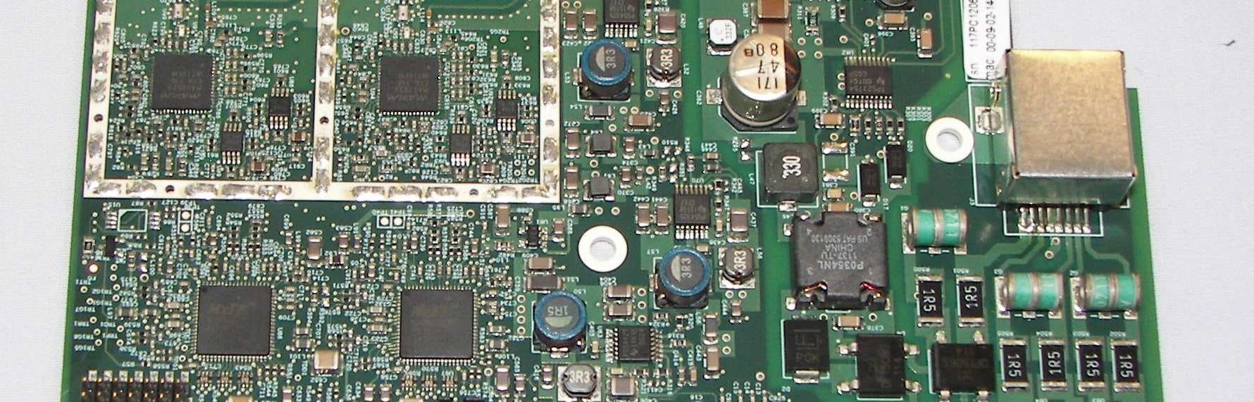
QC8-RDL3000RMA
Jul 17, 2012Advanced Broadband Wireless Infrastructure Solution
Equipment Class
TNB - Licensed Non-Broadcast Station Transmitter