QC8-RDL3000RMAdvanced Broadband Wireless Infrastructure Solution
Redline Communications Inc.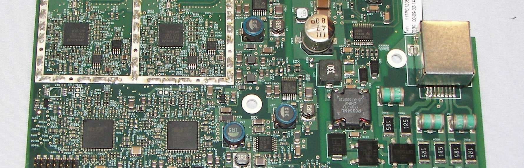
Click to zoom
Application Details
- Equipment Class
- TNB - Licensed Non-Broadcast Station Transmitter
- Date of Grant
- Mar 07, 2012
- Application Purpose
- Original Equipment
- Date of Application
- Mar 07, 2012
- Equipment Note
- Advanced Broadband Wireless Infrastructure Solution
- Frequency Range
- 4950.00000000 - 4980.00000000
- Company
- Redline Communications Inc.
- Country
- Canada
Documents & Files
Document Text
Text extracted from the exhibit documents filed with the FCC. Open a document above to read the original.
Users Manual
70-00184-01-00 Proprietary Redline Communications © 2012 Page 1 of 14 March 1, 2012 RDL-3000 Family Broadband Wireless Radio Platforms RDL-3000-RM Radio Module Product Manual 1 Product Overview ................................................................... 4 2 Conditions of Use ................................................................... 5 3 Module Installation and Service ............................................ 6 4 Final Product Requirements .................................................. 7 5 Regulatory Notices ............................................................... 11 RDL-3000 FAMILY RM PRODUCT MANUAL 70-00184-01-00 Proprietary Redline Communications © 2012 Page 2 of 14 March 1, 2012 Copyright Information All rights reserved March 1, 2012. The information in this document is proprietary to Redline Communications Inc. This document may not in whole or in part be copied, reproduced, or reduced to any medium without prior consent, in writing, from Redline Communications Incorporated. Contact Information: Redline Communications Inc. 302 Town Centre Blvd. Markham, ON Canada L3R 0E8 Web site: http://www.rdlcom.com Email: Inquiries: [email protected] Support: [email protected] Training: [email protected] Document Control: 70-00184-01-00-RDL-3000-RM_Product_Manual-20120301a.doc Disclaimer The statements, configurations, technical data, and recommendations in this document are believed to be accurate and reliable, but are presented without express or implied warranty. Additionally, Redline makes no representations or warranties, either expressed or implied, regarding the contents of this product. Redline Communications shall not be liable for any misuse regarding this product. The information in this document is subject to change without notice. No part of this document shall be deemed to be part of any warranty or contract unless specifically referenced to be part of such warranty or contract within this document. RDL-3000 FAMILY RM PRODUCT MANUAL 70-00184-01-00 Proprietary Redline Communications © 2012 Page 3 of 14 March 1, 2012 TABLE OF CONTENTS 1 Product Overview ................................................................... 4 2 Conditions of Use ................................................................... 5 2.1 General Conditions ............................................................................................ 5 2.2 Country of Use ................................................................................................... 5 2.3 Product Labeling ................................................................................................ 5 3 Module Installation and Service ............................................ 6 3.1 Installation Into a Final Product ........................................................................ 6 3.2 Module Servicing ............................................................................................... 6 3.3 Professional Installation .................................................................................... 6 3.4 Safety Precautions ............................................................................................. 6 3.5 Radio Frequency Safety .................................................................................... 6 4 Final Product Requirements .................................................. 7 4.1 Frequency Bands ............................................................................................... 7 4.2 Antenna Use and Transmit Power .................................................................... 7 4.3 Certified Antennas ............................................................................................. 7 4.4 Power and EIRP Results (MIMO Operation) ..................................................... 7 Operation in the 5725-5850 MHz Band: FCC & IC ......................................... 7 Operation in the 4940-4990 MHz Band: FCC ................................................. 8 Operation in the 4940-4990 MHz Band: IC ..................................................... 9 5 Regulatory Notices ............................................................... 11 FCC Notices: Deployment in USA: ............................................................... 11 Industry Canada Notices: Deployment in Canada: ....................................... 12 LIST OF TABLES Table 1: Approved Antennas ........................................................................................... 7 Table 2: Power & EIRP Results: 5725-5850 MHz FCC & IC - 5 MHz Channel ................ 7 Table 3: Power & EIRP Results: 5725-5850 MHz FCC & IC - 10 MHz Channel .............. 8 Table 4: Power & EIRP Results: 5725-5850 MHz FCC & IC - 20 MHz Channel .............. 8 Table 5: Power & EIRP Results: 4940-4990 MHz FCC - 5 MHz Channel ........................ 8 Table 6: Power & EIRP Results: 4940-4990 MHz FCC - 10 MHz Channel ...................... 9 Table 7: Power & EIRP Results: 4940-4990 MHz FCC - 20 MHz Channel ...................... 9 Table 8: Power & EIRP Results: 4940-4990 MHz IC - 5 MHz Channel ............................ 9 Table 9: Power & EIRP Results: 4940-4990 MHz IC - 10 MHz Channel ........................ 10 Table 10: Power & EIRP Results: 4940-4990 MHz IC - 20 MHz Channel ...................... 10 Table 11: Recommended Safe Distances ...................................................................... 11 Table 12: Recommended Safe Distances ...................................................................... 12 Table 13: Avis - IC RF Distances de séparation sécuritaire recommandées .................. 13 RDL-3000 FAMILY RM PRODUCT MANUAL 70-00184-01-00 Proprietary Redline Communications © 2012 Page 4 of 14 March 1, 2012 1 Product Overview The RDL-3000 Radio Module (RDL-3000-RM) is comprised of a proprietary Media Access Control (MAC) protocol engine and Time Division Duplexing (TDD)/ Orthogonal Frequency Division Duplexing (OFDM) digital …
Text truncated - open the document above for the full version.
Cover Letter(s)
January 24, 2012 Federal Communications Commission Equipment Authorization Branch 7435 Oakland Mills Road Columbia, MD 21046 Applicant: Redline Communications Inc. FCC ID: QC8-RDL3000RM RE: Limited Modular Transmitter Approval for RDL-3000-RM To whom it may concern: Pursuant to the FCC Rules, Part 15 Section 15.212 Modular transmitters and KDB 966369 D01 Module Certification Guide v01r03, Redline Communications, Inc. hereby requests Limited Modular Transmitter Approval for the above listed FCC submittal. This letter affirms that Redline Communications Inc. shall retain complete control over the final installation of the module and will ensure compliance of the end product to all applicable FCC regulations. The module will not be distributed, marketed or sold to the general public and Redline will not make this module available as standalone product. It will be installed in the devices produced by Redline Communications Inc. and its authorized partners. According to the requirements of section 15.212 of FCC rules please note the following statements: 1. Limited Modular Transmitter Approval is being requested since the modular transmitter doesn’t have its own RF shielding. The module has been tested in a stand-alone configuration and complies with all of the FCC requirements at the module level. 2. The input to the module is an Ethernet interface. All modulation and protocol elements are contained within module. There are no other modulation or data inputs to the module that may result in non-compliant operation. 3. The modular transmitter has its own power supply regulation and filtering. 4. The modular transmitter complies with the antenna requirements of Section 15.203 and 15.204(c). The module does not incorporate an integrated antenna, however uses unique MCX RF connectors for antenna connection. The module has been tested with the intended antenna. Approval for additional antenna will be obtained through a Class II permissive change. The modular transmitter will be installed by professional installers trained by Redline Communications. Redline Communications will retain complete control over the final installation of the module ensuring that only approved antenna type will be used with this module. The list of approved antennas is included in the user manual. 5. The modular transmitter has been tested in a stand-alone configuration. It complies with Part 15 and Part 90 Subpart Y regardless of the device / enclosure into which it will be installed. 6. The modular transmitter will be labeled with its own FCC ID: QC8- RDL3000RM, and the chassis of the device / enclosure into which the module is installed will display a label referring to the enclosed module “Contains FCC ID: QC8-RDL3000RM”. 7. The modular transmitter operates under Part 15 and Part 90 Subpart Y to which it has been tested. Users do not have access to controls that may cause the module to operate outside its normal mode of operation. 8. The modular transmitter has been evaluated with the intended antenna and complies with all applicable RF exposure requirements. RF exposure warnings and separation distances are included in the user manual. Sincerely, Rod Cronin Director, Product Line Management Ph: 905.479.8344 x2377 [email protected]
Cover Letter(s)
Page 1 of 1 February 29, 2012 Applicant: Redline Communications Inc. FCC ID: QC8-RDL3000RM IC: 4310A-RDL3000RM Model: RDL-3000-RM MIMO Mode Declaration We, Redline Communications Inc, declare that RDL-3000-RM Advanced Broadband Wireless Infrastructure Solutions, FCC ID: QC8-RDL3000RM, Model: RDL-3000-RM IC: 4310A- RDL3000RM, when operates in MIMO A (STBC/STC) mode or MIMO B (spatial multiplexing) modes, the only modes in which it transmits from both antennas, the transmitter output signals are completely uncorrelated. Sincerely, Rod Cronin Director, Product Line Management Ph: 905.479.8344 x2377 [email protected]
Cover Letter(s)
January 24, 2012 Equipment Autorisation Division Federal Communications Commission 7435 Oakland Mills Road Columbia, MD 21046 FCC ID: QC8-RDL3000RM Product Name: RDL-3000-RM Request for Confidentiality Pursuant to Sections 0.457 and 0.459 of the commissions’ rules, we hereby request that the following documents be held confidential: Block diagrams Schematic diagrams Parts List System overview These materials contain trade secrets and proprietary information and are not customarily released to the public. The public disclosure of this information might be harmful to the company and provide unjustified benefits to our competitors. If you have any queries, please do not hesitate to contact us by our TOLL FREE numbers: OUR TELEPHONE NO.: 1-866-OFDMNOW Sincerely, Dated this 24 Day of January 2012 By: Rod Cronin Signature Printed Title: Director, Product Management Telephone: 905-479-8344x2377 Applicant: Redline Communications Inc
Operational Description
Enterprise and Elte-MT Antenna 5 GHz 1 Confidential and Proprietary © 2012. Redline Communications Inc. Electrical Frequency Range 4.9 - 5.875 GHz Gain 19 dBi VSWR, max. 1.7:1 3 dB Beam-Width, H-Plane, typ. 16 ° 3 dB Beam-Width, E-Plane, typ. 16 ° Side Lobes ETSI TS2 Polarization Linear, Vertical and Horizontal Cross Polarization, min. -20 dB Port to Port Isolation -30 dB Front to Back Ratio ETSI TS2 Horizontal Polarization – Elevation (H-plane) Horizontal Polarization – Azimuth (e-plane) 2 Confidential and Proprietary © 2012. Redline Communications Inc. Vertical Polarization – Elevation (e-plane) Vertical Polarization – Azimuth (h-plane) 3 Confidential and Proprietary © 2012. Redline Communications Inc. Return Loss V-pol Return Loss H-pol 4 Confidential and Proprietary © 2012. Redline Communications Inc.
Parts List/Tune Up Info
Page 1 of 1 To Whom It May Concern FCC ID: QC8-RDL3000RM IC: 4310A-RDL3000RM Model: RDL-3000-RM This is to certify that our RDL-3000-RM system does not need any Tune-up procedure over the power range, or at specific operating power levels when operating in the band 4940-4990MHz or 5725-5850MHz If you have any questions, please contact the undersigned. Dated this 28 Day of February 2012 By: Rod Cronin Signature Printed Title: Director, Product Management Telephone: 905-479-8344x2377 Applicant: Redline Communications Inc
RF Exposure Info
Prediction of MPE limit at a given distance Equation from page 18 of OET Bulletin 65, Edition 97-01where: S = power density P = power input to the antennaG = power gain of the antenna in the direction of interest relative to an isotropic radiatorR = distance to the center of radiation of the antenna 5 MHz channel Maximum peak output power at antenna input terminal: 22.54 (dBm) Maximum peak output power at antenna input terminal: 179.4733627 (mW) Antenna gain(typical): 19 (dBi) Maximum antenna gain: 79.43282347 (numeric) Prediction distance: 120 (cm) Prediction frequency: 4965 (MHz) MPE limit for uncontrolled exposure at prediction frequency: 1 (mW/cm^2) Power density at prediction frequency: 0.078782 (mW/cm^2) 0.787821 (W/m^2) Maximum allowable antenna gain: 30.03572356 (dBi) Margin of Compliance: 11.03572356 2 4 R PG S π = 10 MHz channel Maximum peak output power at antenna input terminal: 22.04 (dBm) Maximum peak output power at antenna input terminal: 159.9558029 (mW) Antenna gain(typical): 19 (dBi) Maximum antenna gain: 79.43282347 (numeric) Prediction distance: 120 (cm) Prediction frequency: 4985 (MHz) MPE limit for uncontrolled exposure at prediction frequency: 1 (mW/cm^2) Power density at prediction frequency: 0.070215 (mW/cm^2) 0.702146 (W/m^2) Maximum allowable antenna gain: 30.53572356 (dBi) Margin of Compliance: 11.53572356 20 MHz channel Maximum peak output power at antenna input terminal: 23.69 (dBm) Maximum peak output power at antenna input terminal: 233.8837239 (mW) Antenna gain(typical): 19 (dBi) Maximum antenna gain: 79.43282347 (numeric) Prediction distance: 120 (cm) Prediction frequency: 4980 (MHz) MPE limit for uncontrolled exposure at prediction frequency: 1 (mW/cm^2) Power density at prediction frequency: 0.102666 (mW/cm^2) 1.026662 (W/m^2) Maximum allowable antenna gain: 28.88572356 (dBi) Margin of Compliance: 9.885723561
Test Report
FCC P90 - Date: Feb 2012 www.nemko.com Compliance test report ID 196334-3TRFWL Date of issue March 6, 2012 FCC 47 CFR Part 90 Private Land Mobile Services Applicant Redline Communications Product Broad-band wireless infrastructure product Model RDL-3000-RM FCC ID QC8-RDL3000RM Nemko Canada Inc., a testing laboratory, is accredited by the Standards Council of Canada. The tests included in this report are within the scope of this accreditation SCC Accredited LAB LAB Accrédité CCN TM w w w . n e m k o . c o m Report reference ID: 196334-3TRFWL Page 2 of 77 Test location Nemko Canada Inc. 303 River Road Ottawa, ON, K1V 1H2 Canada Telephone +1 613 737 9680 Facsimile +1 613 737 9691 Toll free +1 800 563 6336 Website www.nemko.com Tested by Andrey Adelberg, Senior Wireless/EMC Specialist Kevin Rose, Wireless/EMC Specialist Reviewed by March 6, 2012 David Duchesne, Senior EMC/Wireless Specialist Date Limits of responsibility Note that the results contained in this report relate only to the items tested and were obtained in the period between the date of initial receipt of samples and the date of issue of the report. This test report has been completed in accordance with the requirements of ISO/IEC 17025. All results contain in this report are within Nemko Canada’s ISO/IEC 17025 accreditation. Copyright notification Nemko Canada Inc. authorizes the applicant to reproduce this report provided it is reproduced in its entirety and for use by the company’s employees only. Any use which a third party makes of this report, or any reliance on or decisions to be made based on it, are the responsibility of such third parties. Nemko Canada Inc. accepts no responsibility for damages, if any, suffered by any third party as a result of decisions made or actions based on this report. © Nemko Canada Inc. w w w . n e m k o . c o m Report reference ID: 196334-3TRFWL Page 3 of 77 Table of Contents Table of Contents .......................................................................................................................................................................................... 3 Section 1 Report summary .................................................................................................................................................................... 4 1.1 Applicant and manufacturer .............................................................................................................................................................. 4 1.2 Test specifications ............................................................................................................................................................................ 4 1.3 Statement of compliance ................................................................................................................................................................... 4 1.4 Exclusions......................................................................................................................................................................................... 4 1.5 Test report revision history ................................................................................................................................................................ 4 Section 2 Summary of test results ........................................................................................................................................................ 5 2.1 FCC Part 90 Subpart Y test results ................................................................................................................................................... 5 Section 3 Equipment under test (EUT) details ..................................................................................................................................... 6 3.1 Sample information ........................................................................................................................................................................... 6 3.2 EUT information ................................................................................................................................................................................ 6 3.3 Technical information ........................................................................................................................................................................ 6 3.4 Product description and theory of operation ...................................................................................................................................... 6 3.5 EUT exercise details ......................................................................................................................................................................... 6 3.6 EUT setup diagram ........................................................................................................................................................................... 6 3.7 Support equipment ............................................................................................................................................................................ 6 Section 4 Engineering considerations ................................................................................................................................................. 7 4.1 Modifications incorporated in the EUT ............................................................................................................................................... 7 4.2 Technical judgment ........................................................................................................................................................................... 7 4.3 Deviations from laboratory tests procedures ..................................................................................................................................... 7 Section 5 Test conditions .......…
Text truncated - open the document above for the full version.
Contact Information
Applicant
Mirza Wahaj(VP Engineering)
Technical Contact
Redline Communications IncRod Cronin
[email protected]905 479 8344
303 Town Centre Blvd, Suite 100 · Markham · Canada
Test Firm
Nemko Canada IncStuart Beck
Technical Specifications
| # | Rule Parts | Frequency Range | Power Output | Emission | Tolerance |
|---|---|---|---|---|---|
| 3 | 9 | 4.95 GHz - 4.98 GHz | 234.00 mW | 18M5W7D | 1.5 ppm |
Other Applications from Redline Communications Inc.
QC8-RDL3000RMG
Dec 06, 2015Advanced Broadband Wireless Infrastructure Solution
Equipment Class
NII - Unlicensed National Information Infrastructure TXQC8-RDL3000RME
Jul 27, 2015Advanced Broadband Wireless Infrastructure Solution
Equipment Class
TNB - Licensed Non-Broadcast Station TransmitterQC8-RDL3000RMD
Dec 23, 2013Broadband wireless infrastructure product
Equipment Class
TNB - Licensed Non-Broadcast Station Transmitter
QC8-RDL3000RMF
Sep 04, 2013White Space Device with Geo-location - Fixed
Equipment Class
WGF - White Space Device with Geo-location- Fixed
QC8-RDL3000RMA
Jul 17, 2012Advanced Broadband Wireless Infrastructure Solution
Equipment Class
TNB - Licensed Non-Broadcast Station Transmitter