QDWAB009WN200Wireless LAN USB Adapter
AirVast Technology Inc.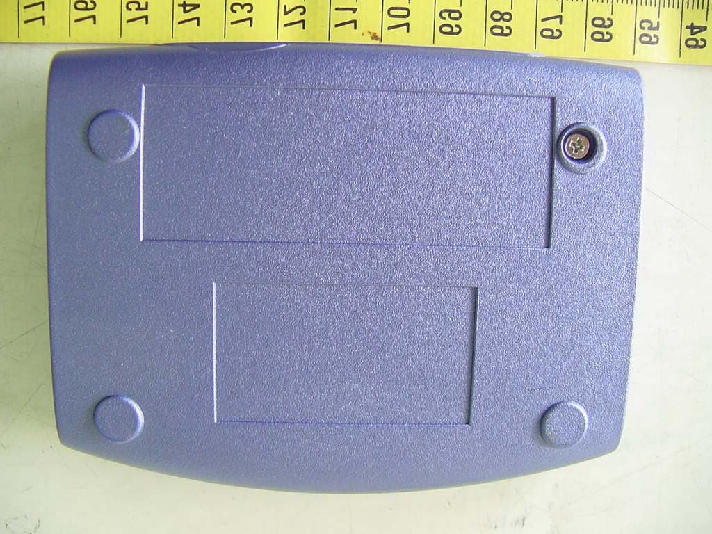
Click to zoom
Application Details
- Equipment Class
- DTS - Digital Transmission System
- Date of Grant
- Aug 14, 2002
- Application Purpose
- Original Equipment
- Date of Application
- Aug 14, 2002
- Equipment Note
- Wireless LAN USB Adapter
- Frequency Range
- 2412.00000000 - 2462.00000000
- Company
- AirVast Technology Inc.
- Country
- Taiwan
Documents & Files
Document Text
Text extracted from the exhibit documents filed with the FCC. Open a document above to read the original.
Users Manual
Wireless LAN USB Adapter WN-200 User’s Manual Version 1.0 1 Copyright © 2002 by Airvast. All rights reserved. No part of this documentation may be reproduced in any form or by any means or used to make any derivative work (such as translation, transformation, or adaptation) without written permission from the copyright owner. All the other trademarks and registered trademarks are the property of their respective owners. Statement of Conditions We may make improvements or changes in the product described in this documentation at any time. The information regarding to the product in this manual are subject to change without notice. We assumes no responsibility for errors contained herein or for direct, indirect, special, incidental or consequential damages w ith the furnishing, performance, or use of this manual or equipment supplied with it, even if the suppliers have been advised of the possibility of such damages. Electronic Emission Notices This device complies with Part 15 of the FCC Rules. Operation is subject to the following two conditions: (1) This device may not cause harmful interference. (2) This device must accept any interference received, including interference that may cause undesired operation. FCC INFORMATION The Federal Communication Commission Radio Frequency Interference Statement includes the follow ing paragraph: The equipment has been tested and found to comply w ith the limits for a Class B Digital Device, pursuant to part 15 of the FCC Rules. These limits are designed to provide reasonable protection against harmful interference in a residential installation. This equipment generates, uses and can radiate radio frequency energy and, if not installed and used in accordance with the instruction, may cause harmful interference to radio communication. However, there is no grantee that interference w ill not occur in a particular installation. If this equipment dose cause harmful interference to radio or television reception, w hich can be determined by turni ng the equipment off and on, the user is encouraged to try to correct the interference by one or more of the following measures: --Reorient or relocate the receiving antenna. --Increase the separation between the equipment and receiver. --Connect the equipment into an outlet on a circuit different from that to which the receiver is connected. --Consult the dealer or an experienced radio/TV technician for help. The equipment is for home or office use. IMPORTANT NOTE: To comply with the FCC RF exposure compliance requirements, a separation distance of at least 20cm must be maintained between the antenna of this device and all persons. No change to the antenna or the device is permitted. Any change to the antenna or the device could result in the device exceeding the RF exposure requirements and void user’s authority to operate this device. The changes or modifications not expressly approved by the party responsible for compliance could void the user’s authority to operate the equipment. 2 1. INTRODUCTION This document describes how to install the WN-200, Wireless LAN USB Adapter. Wireless LAN is local area netw orking w ithout w ires, w hich uses radio frequencies to transmit and receive data between PC’s or other network devices. Wireless LAN is able to configure independent netw orks and infrastructure networks. The former is suitable for small or temporary peer-to-peer configurations, and the later is offering fully distributed data connectivity via micro cells and roaming. 2. INSTALLATION 2.1 Check the Product Package Before starting installation, please make sure the package you purchased includes the following three items: 1) Wireless LAN USB Adapter. 2) USB cable. 3) CD-ROM (containing Driver/Utility, and User ’s Manual). Please contact your vendor if anything is missing or damaged. 2.2 Meet the Minimum Requirements To install the WN-200 successfully, your computer should meet the following minimum requirements: 1) An available USB port. 2) Windows 98, Me, 2000, or XP operating system. 3) Minimum 5 Mbytes free disk space for installing the driver and the utility program. 2.3 Installation Please refer to the proper section corresponding with operating system you are using to install the WN-200. Installation Procedure for Windows 98 and 98SE Users: 1. Turn on your computer. 2. Make sure that WN-200 has not been connected to the computer yet. 3. Place the supplied CD-ROM to the CD-ROM drive. The Setup Utility should run automatically. If it does not, please run d:\setup.exe manually, where d: is the letter of the CD-ROM drive. 4. Click the Next button after you see a welcome message. 5. Choose the Destination Folder where the configuration utility will be stored by clicking the Browse button, or leave it as default, and then click the Next button. 6. Fill in the Program Folder Name or leave it as default, and then click the Next button. 7. On the InstallShield Wizard Complete screen, select “Yes, I want to restart my computer now” and click the Finish button. 8. After your computer is restarted, connect one end of the USB cable to WN-200, and the other end to computer’s USB port. 9. Once connecting, Windows loads the driver automatically. 10. As soon as the driver is loaded, you need to configure WN-200 with the desired settings by clicking the icon of Wireless LAN Monitor at the task bar. Installation Procedure for Windows Me Users: 1. Turn on your computer. 2. Make sure that WN-200 has not been connected to the computer yet. 3. Place the supplied CD-ROM to the CD-ROM drive. The Setup Utility should run automatically. If it does not, please run d:\setup.exe manually, where d: is the letter of the CD-ROM drive. 4. Click the Next button after you see a welcome message. 5. Choose the Destination Folder where the configuration utility will be stored by clicking the Browse button, or leave it as default, and then click the Next button. 6. Fill in the Program Folder Name or leave it as default, and then click the Nex…
Text truncated - open the document above for the full version.
Cover Letter(s)
From: etcemi-H [[email protected]] Sent: Wednesday, August 14, 2002 11:41 PM To: Mike Kuo Cc: [email protected] Subject: Re: AirVast Technology Inc., FCC ID:QDWAB009WN200, AN02T2174 Hi Mike, We have revised the user's manual following your instructions. Please refer to the attached files. For Question#2, the measurement data plots are also provided in the attached files. Best regards, Will Yauo / ETC ----- Original Message ----- From: Mike Kuo <[email protected]> To: Will Yauo (E-mail) <[email protected]>; Will Yauo-Personal (E-mail) <[email protected]> Sent: Wednesday, August 14, 2002 7:16 AM Subject: FW: AirVast Technology Inc., FCC ID:QDWAB009WN200, AN02T2174 > > > -----Original Message----- > From: CERTADM > Sent: Tuesday, August 13, 2002 4:16 PM > To: '[email protected]' > Subject: AirVast Technology Inc., FCC ID:QDWAB009WN200, AN02T2174 > > > Notice_content > ------------- > Question #1: The separation distance indicated in page 1 of user manual is > 2.5cm. For device with separation distance less than 20cm is considered as > portable device due to near field radiation. This device should be > considered as mobile device since the user does not require to operate this > device within 20cm of body. Please change the separation distance from > 2.5cm to 20cm and submit revised user manual. > > Question #2: Please provide spurious emission measurement data at antenna > terminal up to 10th harmonics of fundamental frequency. > > Best Regards > > Mike Kuo / TCB Certifier > The items indicated above must be submitted before processing can continue > on the above referenced application. Failure to provide the requested > information within 60 days of the original e-mail date may result in > application dismissal and forfeiture of the filing fee. Also, please note > that partial responses increase processing time and should not be submitted. > Any questions about the content of this correspondence should be directed to > the e-mail address listed below the name of the sender. >
External Photos
ETC Report No. : ET91R-07-072-01 FCC ID.: QDWAB009WN200 Rev. No 1.0 ONSTRUCTED PHOTOS of EUT Total View of EUT Top View of EUT ETC Report No. : ET91R-07-072-01 FCC ID.: QDWAB009WN200 Rev. No 1.0 CONSTRUCTED PHOTOS of EUT Bottom View of EUT Side View of EUT ETC Report No. : ET91R-07-072-01 FCC ID.: QDWAB009WN200 Rev. No 1.0 CONSTRUCTED PHOTOS of EUT Side View of EUT
ID Label/Location Info
Bottom View of EUT This statement will be placed in User’s Manual This device complies with part 15 of the FCC Rules. Operation is subject to the following two conditions: (1) this device may not cause harmful interference and (2) this device must accept any interference received, including interference that may cause undesired operation. Label Wireless LAN USB Adapter FCC ID.: QDWAB009WN200 Model: WN-200 〔 44mm 〕 ︹ 24mm ︺
Internal Photos
ETC Report No. : ET91R-07-072-01 FCC ID.: QDWAB009WN200 Rev. No 1.0 CONSTRUCTED PHOTOS of EUT Internal View of EUT Component View of Main PCB ETC Report No. : ET91R-07-072-01 FCC ID.: QDWAB009WN200 Rev. No 1.0 CONSTRUCTED PHOTOS of EUT Solder View of Main PCB Component View of Main PCB ETC Report No. : ET91R-07-072-01 FCC ID.: QDWAB009WN200 Rev. No 1.0 CONSTRUCTED PHOTOS of EUT Solder View of Main PCB
Operational Description
Wireless LAN is local area networking without wires, which uses radio frequencies to transmit and receive data between PC’s or other network devices. Wireless LAN is able to configure independent networks and infrastructure networks. The former is suitable for small or temporary peer-to-peer configurations, and the later is offering fully distributed data connectivity via micro cells and roaming. The Wireless LAN USB Adapter designed with a transmitting method of direct sequence spread spectrum is for local area network operation, which operates at 2.4 GHz ISM band and data rate up to 11 Mbps.
RF Exposure Info
Rev. No 2.1 RF Maximum Permissible Exposure Measurement Report of E.U.T. : Wireless LAN USB Adapter FCC ID. : QDWAB009WN200 MODEL : WN-200 for APPLICANT : AirVast Technology Inc. ADDRESS : 4F-1, NO. 1, LN. 21, HSIN HUA RD., KUEISHAN INDUSTRIAL PARTK, TOYUAN 330, TAIWAN, R.O.C. Test Performed by ELECTRONICS TESTING CENTER, TAIWAN NO. 34, LIN 5, DING FU TSUN, LINKOU HSIANG, TAIPEI HSIE, TAIWAN, R.O.C. Tel:(02)26023052, 26023054 Fax:(02)26010910 Report Number : ET91R-07-072-01 ETC Report No. : ET91R-07-072-01 FCC ID.: QDWAB0009WN200 Rev. No 2.1 TEST REPORT CERTIFICATION Applicant : AirVast Technology Inc. 4F-1, NO. 1, LN. 21, HSIN HUA RD., KUEISHAN INDUSTRIAL PARK, TAOYUAN 330, TAIWAN, R.O.C. Manufacturer : AirVast Technology Inc. 4F-1, NO. 1, LN. 21, HSIN HUA RD., KUEISHAN INDUSTRIAL PARK, TAOYUAN 330, TAIWAN, R.O.C. Description of EUT : a) Type of EUT : Wireless LAN USB Adapter b) Trade Name : AirVast c) Model No. : WN-200 d) Power Supply : From Notebook PC Regulation Applied : IEEE C95.1-1991, FCC 47 CFR Part 1 and Part 2 I HEREBY CERTIFY THAT: The data shown in this report were made in accordance with the procedures given in IEEE C95.1, and the energy emitted by the device was founded to be within the limits applicable. I assume full responsibility for accuracy and completeness of these data. Note: 1. The result of the testing report relates only to the item tested. 2. The testing report shall not be reproduced expect in full, without the written approval of ETC. Issued Date : Aug. 09, 2002 Test Engineer : ( S. S. Liou ) Approve & Authorized Signer : Will Yauo, Manager EMC Detp. II of ELECTRONICS TESTING CENTER, TAIWAN ETC Report No. : ET91R-07-072-01 FCC ID.: QDWAB0009WN200 Rev. No 2.1 Table of Contents Page 1 GENERAL INFORMATION....................................................................................................... 1 1.1 Product Description...................................................................................................................... 1 1.2 Characteristics of Device ............................................................................................................. 1 1.3 Test Methodology......................................................................................................................... 1 1.4 Test Facility.................................................................................................................................. 1 2 PROVISIONS APPLICABLE...................................................................................................... 2 2.1 Definition...................................................................................................................................... 2 2.2 Relative Requirement for Compliance ......................................................................................... 2 3. SYSTEM TEST CONFIGURATION........................................................................................... 3 3.1 Justification................................................................................................................................... 3 3.2 Devices for Tested System ........................................................................................................... 3 4 M AXIMUM P ERMISSIBLE E XPOSURE M EASUREMENT .................................................................. 4 4.1 Applicable Standard ..................................................................................................................... 4 4.2 Measurement Procedure............................................................................................................... 4 4.3 Measurement Instrument.............................................................................................................. 5 4.4 Power Desity Data........................................................................................................................ 5 4.5 Measurement Setup Photos .......................................................................................................... 6 ETC Report No. : ET91R-07-072-01 Page 1 of 6 Pages FCC ID.: QDWAB009WN200 Rev. No 2.1 1 GENERAL INFORMATION 1.1 Product Description a) Type of EUT : Wireless LAN USB Adapter b) Trade Name : AirVast c) Model No. : WN-200 d) Power Supply : From Notebook PC 1.2 Characteristics of Device Wireless LAN is local area networking without wires, which uses radio frequencies to transmit and receive data between PC’s or other network devices. Wireless LAN is able to configure independent networks and infrastructure networks. The former is suitable for small or temporary peer-to-peer configurations, and the later is offering fully distributed data connectivity via micro cells and roaming. The Wireless LAN USB Adapter designed with a transmitting method of direct sequence spread spectrum is for local area network operation, which operates at 2.4 GHz ISM band and data rate up to 11 Mbps. 1.3 Test Methodology The Maximum Permissible Exposure (MPE) was performed according to the procedures illustrated in IEEE C95.1-1991. 1.4 Test Facility The open area test site and conducted measurement facility used to collect the radiated data is located on the roof top of Building at No.34, Lin 5, Ding Fu Tsun, Linkou Hsiang, Taipei Hsien, Taiwan, R.O.C. This site has been fully described in a report submitted to the FCC, and accepted in a letter dated Feb. 10, 2000. ETC Report No. : ET91R-07-072-01 Page 2 of 6 Pages FCC ID.: QDWAB009WN200 Rev. No 2.1 2 PROVISIONS APPLICABLE 2.1 Definition MPE in Occupational / Controlled Environments: Persons are exposed as a consequence of their employment provided those persons are fully aware of the potential for exposure and can exercise control over their exposure. Also apply to a individual is transient through a location where occupational / controlled limits apply provided he or she is made aware of the potatial for exposure. MPE in General Population / Uncontroll…
Text truncated - open the document above for the full version.
Test Report
Rev. No 2.0 FCC Part 15 EMI TEST REPORT of E.U.T. : Wireless LAN USB Adapter FCC ID. : QDWAB009WN200 MODEL : WN-200 for APPLICANT : AirVast Technology Inc. ADDRESS : 4F-1, NO. 1, LN. 21, HSIN HUA RD., KUEISHAN INDUSTRIAL PARK, TAOYUAN 330, TAIWAN, R.O.C. Test Performed by ELECTRONICS TESTING CENTER, TAIWAN NO. 34, LIN 5, DING FU TSUN, LINKOU HSIANG TAIPEI HSIEN, TAIAWN, R.O.C. Tel:(02)26023052, 26023054 Fax:(02)26010910 Report Number : ET91R-07-072-01 ETC Report No. : ET91R-07-072-01 FCC ID.: QDWAB009WN200 Rev. No 1.0 TEST REPORT CERTIFICATION Applicant : AirVast Technology Inc. 4F-1, NO. 1, LN. 21, HSIN HUA RD., KUEISHAN INDUSTRIAL PARK, TAOYUAN 330, TAIWAN, R.O.C. Manufacturer : AirVast Technology Inc. 4F-1, NO. 1, LN. 21, HSIN HUA RD., KUEISHAN INDUSTRIAL PARK, TAOYUAN 330, TAIWAN, R.O.C. Description of EUT : a) Type of EUT : Wireless LAN USB Adapter b) Trade Name : AirVast c) Model No. : WN-200 d) Power Supply : From Notebook PC Regulation Applied : FCC Rules and Regulations Part 15 Subpart B & C (2001) I HEREBY CERTIFY THAT: The data shown in this report were made in accordance with the procedures given in ANSI C63.4, and the energy emitted by the device was founded to be within the limits applicable. I assume full responsibility for accuracy and completeness of these data. Note: 1. The result of the testing report relate only to the item tested. 2. The testing report shall not be reproduced expect in full, without the written approval of ETC. Issued Date : Aug. 09, 2002 Test Engineer : ( Falcon Shi ) Approve & Authorized Signer : Will Yauo, Manager EMC Dept. II of ELECTRONICS TESTING CENTER, TAIWAN ETC Report No. : ET91R-07-072-01 FCC ID.: QDWAB009WN200 Rev. No 1.0 Table of Contents Page 1 GENERAL INFORMATION....................................................................................................... 1 1.1 Product Description...................................................................................................................... 1 1.2 Characteristics of Device ............................................................................................................. 1 1.3 Test Methodology......................................................................................................................... 1 1.4 Test Facility.................................................................................................................................. 1 2 PROVISIONS APPLICABLE...................................................................................................... 2 2.1 Definition...................................................................................................................................... 2 2.2 Requirement for Compliance ....................................................................................................... 3 2.3 Restricted Bands of Operation ..................................................................................................... 6 2.4 Labeling Requirement .................................................................................................................. 6 2.5 User Information........................................................................................................................... 7 3. SYSTEM TEST CONFIGURATION........................................................................................... 8 3.1 Justification................................................................................................................................... 8 3.2 Devices for Tested System ........................................................................................................... 8 4 RADIATED EMISSION MEASUREMENT............................................................................... 9 4.1 Applicable Standard ..................................................................................................................... 9 4.2 Measurement Procedure............................................................................................................... 9 4.3 Measuring Instrument................................................................................................................. 11 4.4 Radiated Emission Data ............................................................................................................. 12 4.4.1 RF Portion...............................................................................................................................12 4.4.2 Other Emission........................................................................................................................15 4.5 Field Strength Calculation .......................................................................................................... 15 4.6 Photos of Radiation Measuring Setup ........................................................................................ 16 5 CONDUCTED EMISSION MEASUREMENT........................................................................ 17 5.1 Standard Applicable ................................................................................................................... 17 5.2 Measurement Procedure............................................................................................................. 17 5.3 Conducted Emission Data .......................................................................................................... 18 5.4 Result Data Calculation.............................................................................................................. 18 5.5 Conducted Measurement Equipment ......................................................................................... 19 5.6 Photos of Conduction Measuring Setup ..................................................................................... 20 6 ANTENNA REQUIREMENT.................................................................................................... 21 6.1 Standard Applicable …
Text truncated - open the document above for the full version.
Test Setup Photos
ETC Report No. : ET91R-07-072-01 FCC ID.: QDWAB009WN200 Rev. No 1.0 Photos of Radiation Measuring Setup ETC Report No. : ET91R-07-072-01 FCC ID.: QDWAB009WN200 Rev. No 1.0 Photos of Conduction Measuring Setup
Test Setup Photos
ETC Report No. : ET91R-07-072-01 FCC ID.: QDWAB0009WN200 Rev. No 2.1 Measurement Setup Photos
Contact Information
Applicant
Guo-Rong Hwang(Vice President)
Test Firm
Electronics Testing Center, TaiwanWin-Po Tsai
Technical Specifications
| # | Rule Parts | Frequency Range | Power Output |
|---|---|---|---|
| 1 | 15C,15C | 2.41 GHz - 2.46 GHz | 60.30 mW |
Other Applications from AirVast Technology Inc.
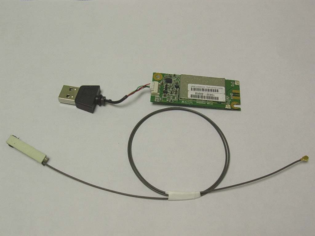
QDWWM168GC
Aug 09, 2004802.11g WLAN USB Module
Equipment Class
DTS - Digital Transmission System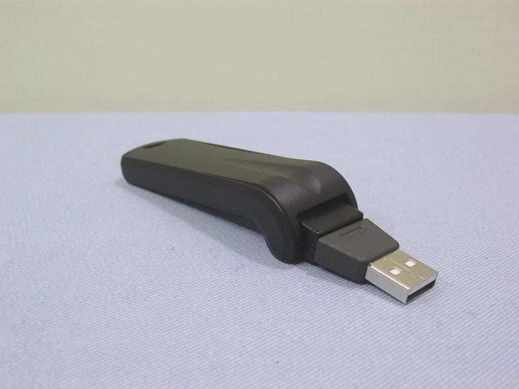
QDWWN250GC
Jun 14, 2004802.11 b/g WLAN USB Stick
Equipment Class
DTS - Digital Transmission System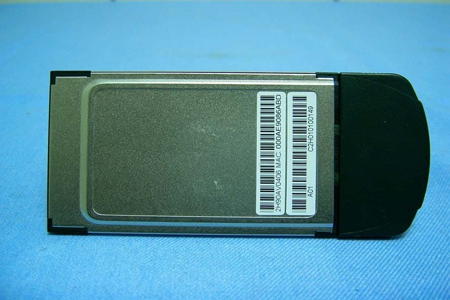
QDWWN113SH18
Mar 11, 2004802.11b WLAN PCMCIA Card W/Detachable Antenna
Equipment Class
DTS - Digital Transmission System
QDWWN500
Mar 08, 2004802.11b WLAN CF card
Equipment Class
DTS - Digital Transmission System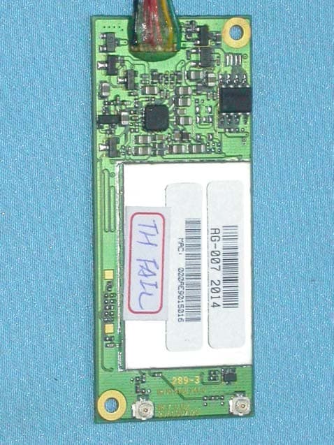
QDWWM168GI
Jan 12, 2004802.11g WLAN USB Module
Equipment Class
DTS - Digital Transmission System