QF5MS-009RFCordless Mouse
Newmen Technology Corp., Ltd.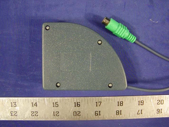
Click to zoom
Application Details
- Equipment Class
- DXX - Part 15 Low Power Communication Device Transmitter
- Date of Grant
- Jun 18, 2002
- Application Purpose
- Original Equipment
- Date of Application
- Jun 18, 2002
- Equipment Note
- Cordless Mouse
- Frequency Range
- 27.04000000 - 27.14000000
- Country
- China
Documents & Files
Document Text
Text extracted from the exhibit documents filed with the FCC. Open a document above to read the original.
Users Manual
Radio Wireless Wheel Mouse User’s Guide Model: RFT009 Trademark Recognition Windows, Office 97 and MS-IntelliMouse are registered trademarks of Microsoft Corp. MN-RFSW35-NC — 1 — THIS DEVICE COMPLIES WITH PART 15 OF THE FCC RULES. OPERATION IS SUBJECT TO THE FOLLOWING TWO CONDITIONS: (1) THIS DEVICE MAY NOT CAUSE HARMFUL INTERFERENCE AND (2) THIS DEVICE MUST ACCEPT ANY INTERFERENCE RECEIVED, INCLUDING INTERFERENCE THAT MAY CAUSE UNDESIRED OPERATION. Federal Communications Commission Requirements The equipment has been tested and found to comply with the limits for Class B Digital Device, pursuant to part 15 of the FCC Rules. These limits are designed to provide reasonable protection against harmful interference in a residential installation. This equipment generates, uses and can radiate radio frequency energy and, if not installed and used in accordance with the instruction, may cause harmful interference to radio communication. However, there is no guarantee that interference will not occur in a particular installation. If this equipment does cause harmful interference to radio or television reception, which can be determined by turning the equipment off and on, the user is encouraged to try to correct the interference by one or more of the following measures: z Reorient of relocate the receiving antenna. z Increase the separation between the equipment and receiver. z Connect the equipment into an outlet on a circuit different from that to which the receiver is connected. z Consult the dealer or an experienced radio/TV technician for help. The changes or modifications not expressly approved by the party responsible for compliance could void the user's authority to operate the equipment. — 2 — Introduction Congratulations on your purchase! Your new RF-Mouse is easy to install and offers you a host of useful features. The Radio receiver can be conveniently placed to give you the freedom you need while working. The vertical wheel allows you to scroll, or zoom in and out in a document. You can program the mouse buttons to launch the NetJump or LuckyJump for a quick start to programs you run frequently. And, your RF-Mouse has a unique ID code, so other RF (Radio Frequency) pointing devices won’t affect your system. Connecting the RF-Mouse Receiver The RF-Mouse receiver connects to your computer in the same way as a conventional mouse allowing you to place the receiver wherever is convenient on your desktop. 1. Locate the round 6-pin PS/2 mouse port on the back of your computer. 2. Insert the PS/2 connector into the PS/2 port. Locating the RF-Mouse Receiver Your RF-Mouse has limitations on the range or distance from the receiver. To make sure that your mouse sends and receives properly, refer to the following: 1. For optimal performance, place the receiver at least 8 inches (20 centimeters) away from other electrical devices, such as the computer, the monitor, or external storage drives. 2. The RF-Mouse should be no farther than 3.3 feet (1.0 meter) from the mouse receiver. This will ensure optimal communication between the mouse and receiver. 3. If you are working on a metallic surface, try using a mouse pad and turning the receiver face down for better reception. 4. Switch frequency channels to prevent interference from other RF pointing devices. (See the following section for more information.) Selecting the Frequency Channel The RF-Mouse operates on two frequency channels. To prevent interference when using two RF Mice in close proximity a different frequency channel should be used for each mouse. Refer to the following to change the frequency channel for your mouse: 1. Set the frequency channel on the receiver to 1 or 2. 2. Remove the battery cover from the mouse (see the following Inserting the Batteries section). 3. Set the frequency channel on the mouse to 1 or 2. (The frequency channel for mouse and receiver must be the same.) — 3 — Inserting the Batteries The RF-Mouse uses two AAA batteries. For best performance, use only alkaline batteries. Refer to the following to insert the batteries: 1. Press the tab on the bottom of the mouse cover as shown here and remove the cover. 2. Insert the two AAA batteries. (The correct polarity is indicated on the battery compartment casing.) 3. Replace the cover. Checking the Batteries power To check the battery power, right-click the mouse icon in the Taskbar. Choose the “Check RF-Mouse Status” option to display the RF-Mouse Status window. The current battery percentage charge is shown. Installing the Mouse Software Before you can take advantage of the many features your mouse offers, you must install the driver. The driver is on the installation diskette that came packaged with your mouse. Windows 95/98/Me/2000/NT4.0/XP installation 1. Connect the mouse to your computer. 2. Insert the installation diskette into your floppy disk drive. 3. Click the Start button and then click Run. 4. In the Run dialog window, type A:\setup, where “A” is the letter of your floppy disk drive. 5. Click OK and follow the instructions on your screen to complete the installation. The RF-Mouse ID code Each RF-Mouse is assigned a unique ID code at manufacture, so the receiver only picks up the signal from your mouse and prevents other RF-Mouse radio signals from operating on your computer. This feature can also be disabled, allowing other RF-pointing devices to operate your computer. Connecting the RF-Mouse ID Code When the driver installation is finished your computer reboots and the RF- Mouse window (shown on the right) appears. CONNECT ID: Move the RF-Mouse for a few seconds to establish a connection, then click Connect ID. The unique ID code of your mouse is recognized and another RF pointing device will not function on your computer. Exit: Click Exit if no other RF pointing devices are within 3 meters range or if you want other RF pointing devices to be able to access your computer. Changing the RF-Mouse ID Code You can use a new RF-Mouse on your computer without cha…
Text truncated - open the document above for the full version.
External Photos
APPENDIX C - EUT EXTERNAL PHOTOGRAPHS Transmitter Chassis - Top View Transmitter Chassis - Bottom View Receiver Chassis - Top View Receiver Chassis - Bottom View Receiver Chassis - Switch Side
ID Label/Location Info
APPENDIX A - FCC PRODUCT LABELING AND WARNING STATEMENT FCC ID Label Specifications : Text is black in color and is left justified. Labels are printed in indelible ink on permanent adhesive backing and shall be affixed at a conspicuous location on the EUT. Proposed Label Location on EUT Bottom Side of EUT/FCC ID Label Proposed Location FCC Warning Statement If the EUT is too small, the FCC statement could be presented in the user manual. Generally, appendix B contains one copy of user manual. The following is one sample of the FCC Statement: “ This device complies with part 15 of the FCC Rules. Operation is subject to the following two conditions: (1) This device may not cause harmful interference, and (2) this device must accept any interference received, including interference that may cause undesired operation.”
Internal Photos
APPENDIX C - EUT INTERNAL PHOTOGRAPHS Transmitter Main Board - Component View Transmitter Main Board - Solder View Receiver Main Board - Component View Receiver Main Board - Solder View
Operational Description
Purpose: RFfOO9 is a wireless mouse, identical to current mice, adds the convenience of being free of cable. The system uses the 27 MHz ISM band. The transmitter realize a low power mode for batteries saving. this wireless mouse (RFfOO9) works with the RFRX-5 or all compatible receiver. System Microprocessor: Radio transmission: Number of channels: channel select method: Carrier frequencies: Modulation: Transmission range: Power consumption: Effective radiated power Antenna : Battery: power shut off voltage: Data rate: Operating voltage: Current coDSwnption (operation): (stand-by): (sleep): RFTI70E4 mono directional, from mouse to computer only. 2 slide switch. 27.045MHz / 27.145MHz. FSK over 1.5m typical, free space. - SdBm typical when in movement. -45dBm typical. inductive loop antenna, integrated on printed circuit board. alkaline, 2 x AAA. 1.6v ::!: 5%. 5800 bit/so 1.8-3.3 Vdc. 10rnA. 2.0mA. I 00uA. 520 OPI . chock-per: 1,000,000 cycles. 3 button, I wheel. 500 Miles. Max: 100gf. 876mm/sec. resolution: micro switch: number of button/wheel : running life: operation force in any direction tracking speed: A4TECH CONFIDENTIAL Saturday, May 11,2002
Schematics
1 2 34 A BC D 4 3 2 1 D CB A Title Number Revision Siz e A4 Date: 15-May-2002 Sheet of File: E:\HUANGBIN\Mysch.ddb Drawn By: L21uH 0307 Q32SC2668 Q22SC2668 Q1 2SC2668 R710R RR23.9K RR130K R610K R8ANC R43.9K R1039K R51.5K R3100K R910R C16102 C1512P C9102 C13100P C11150P C1220P C1103 C10102 C339P C2104 CC1104 C5100P C6150P C827P X2 13.5725 X1 13.5225 SW1 SW- SPDT V_BAT POWER ON V_BAT POWER ON DATAIN + EC1100uF IRY322DP1/JIRX322DP1/J IRZY322L1/J PHY LTR5576DP1 PHX LTR5576DP1 PHZXLTR-5576DL1 RXB51K RZB51K RX170R RZ390R QX NPN QZNPN VCC VCC LED LEDZ VCC VCCVCC Y1Y2X1X2 SDSU VSS 1 OUT 2 LX 3 Q1 XC6383A301PR + TC122uF/16V VCC + EC1 100uF/10V VBAT DS11N5819 BT1BATTERY SWL DM-03P-S SWM DM-03P-S SWR DM-03P-S VCC LMR P52 1 P53 2 TCC 3 RST 4 VSS 5 P60/INT 6 P61 7 P62 8 P63 9 P64 10 P65 11 P66 12 P67 13 VDD 14 CLKO 15 CLKI 16 P50 17 P51 18 U1 EM78P156 X14MHz C10.1uF VCC C40.1uF R1100K VCC LEDZLEDDATAINRL MXRSTY1 SDY2 SUX1 SRX2 SL R2100K 1% C15 332 5% PWR V_BAT PR1A10K Y1Y2X1X2 LS 100uHINDUCTOR IRON ANT1 ANTENNA C6A15P C14NC D1NC [ROHM RN731V(SMD)] R8 0R CH1=LEFT CH2=RIGHT ALL CAPACITOR=NPO 5% EXCEPT ByPass 13.5225MHz*2=27.04513.5275MHz*2=27.145 RFT009
Test Report
Note: This test report is specially limited to the above client company and product model only. It may not be duplicated without prior written consent of Bay Area Compliance Laboratory Corporation. This report must not be used by the client to claim product endorsement by NVLAP or any agency of the U.S. Government. FCC ID PER PART 15.227 EMI MEASUREMENT AND TEST REPORT For Newmen Technology Corp, Ltd. Building A Baolong Industry Zone, No 491 Dalang South Road, Longhua Guangdong, China FCC ID: QF5MS-009RF June 18, 2002 This Report Concerns: Original Report Equipment Type: Cordless Mouse, ITE Test Engineer: Benjamin Jin Test Date: April 30, 2002 Reviewed By: Jeff Lee Prepared By: Bay Area Compliance Laboratory Corporation 230 Commercial Street Sunnyvale, CA 94085 Tel: (408) 732-9162 Fax: (408) 732-9164 Newmen Technology Copr., Ltd. FCC ID: QF5MS-009RF Report # R0204126Rpt Page 2 of 14 FCC ID Per 15.227 Report TABLE OF CONTENTS 1 - GENERAL INFORMATION..................................................................................................................................3 1.1 PRODUCT DESCRIPTION FOR EQUIPMENT UNDER TEST (EUT) ..............................................................................3 1.2 OBJECTIVE.............................................................................................................................................................3 1.3 RELATED SUBMITTAL(S)/GRANT(S).......................................................................................................................3 1.4 TEST METHODOLOGY............................................................................................................................................3 1.5 TEST FACILITY.......................................................................................................................................................3 1.6 TEST EQUIPMENT LIST...........................................................................................................................................4 1.7 HOST SYSTEM CONFIGURATION.............................................................................................................................4 1.8 LOCAL SUPPORT EQUIPMENT LIST AND DETAILS...................................................................................................5 1.9 EXTERNAL I/O CABLES LIST AND DETAILS............................................................................................................5 2 - SYSTEM TEST CONFIGURATION.....................................................................................................................6 2.1 JUSTIFICATION.......................................................................................................................................................6 2.2 EUT EXERCISE SOFTWARE....................................................................................................................................6 2.3 SPECIAL ACCESSORIES...........................................................................................................................................6 2.4 SCHEMATICS AND BLOCK DIAGRAM......................................................................................................................6 2.5 EQUIPMENT MODIFICATIONS.................................................................................................................................6 2.6 TEST SETUP CONFIGURATION................................................................................................................................7 2.7 TEST SETUP BLOCK DIAGRAM...............................................................................................................................7 3 - SUMMARY OF TEST RESULTS..........................................................................................................................8 4 - CONDUCTED EMISSIONS TEST ........................................................................................................................9 4.1 MEASUREMENT UNCERTAINTY..............................................................................................................................9 4.2 EUT SETUP............................................................................................................................................................9 4.3 SPECTRUM ANALYZER SETUP................................................................................................................................9 4.4 TEST PROCEDURE................................................................................................................................................10 4.5 SUMMARY OF TEST RESULTS...............................................................................................................................10 4.6 CONDUCTED EMISSIONS TEST DATA...................................................................................................................10 4.7 PLOT OF CONDUCTED EMISSIONS TEST DATA.....................................................................................................10 5 - RADIATED EMISSION TEST ............................................................................................................................12 5.1 MEASUREMENT UNCERTAINTY............................................................................................................................12 5.2 EUT SETUP..........................................................................................................................................................12 5.3 SPECTRUM ANALYZER SETUP..............................................................................................................................12 5.4 TEST PROCEDURE................................................................................................................................................13 5.5 CORRECTED AMPLITUDE & MARG…
Text truncated - open the document above for the full version.
Contact Information
Applicant
Frank Zhu(President)
Test Firm
Bay Area Compliance LaboratoryJohn Chan
Technical Specifications
| # | Rule Parts | Frequency Range | Power Output |
|---|---|---|---|
| 1 | 15C | 27.04 MHz - 27.14 MHz | - |
Other Applications from Newmen Technology Corp., Ltd.
QF5MS-037OR
May 10, 2005Wireless Mouse
Equipment Class
DXX - Part 15 Low Power Communication Device Transmitter
QF5MS-020OR
Feb 02, 2004Wireless Mouse
Equipment Class
DXX - Part 15 Low Power Communication Device Transmitter
QF5MS-025OR
Aug 25, 2003Nemwen Mouse
Equipment Class
DXX - Part 15 Low Power Communication Device Transmitter
QF5MS-009TP
Apr 01, 2003mouse
Equipment Class
JBP - Part 15 Class B Computing Device Peripheral
QF5MS-019RF
Feb 04, 2003Wireless Mouse
Equipment Class
DXX - Part 15 Low Power Communication Device Transmitter