QH7HMDS-04GCUSB FLASH DRIVE
HANA Micron Inc.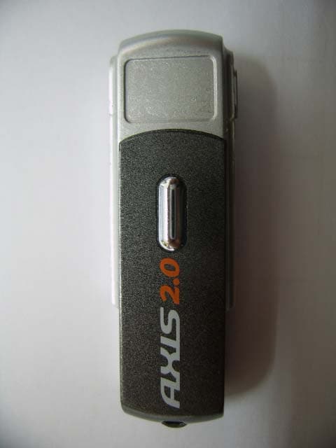
Click to zoom
Application Details
- Equipment Class
- JBP - Part 15 Class B Computing Device Peripheral
- Date of Grant
- Apr 30, 2006
- Application Purpose
- Original Equipment
- Date of Application
- Apr 30, 2006
- Equipment Note
- USB FLASH DRIVE
- Company
- HANA Micron Inc.
- Country
- South Korea
Documents & Files
Document Text
Text extracted from the exhibit documents filed with the FCC. Open a document above to read the original.
Users Manual
- - - - - - - - - - - - - - - - - - - - U.S. FCC CLASS B NOTICE Caution : Any changes or modifications in construction of this device which are not expressly approved by the party responsible for compliance could void the user’s authority to operate the equipment. This equipment has been tested and found to comply with the limits for a Class B Digital Device, pursuant to Part 15 of the FCC Rules. These limits are designed to provide reasonable protection against harmful interference in a residential installation. This equipment generates, uses, and can radiate radio frequency energy, if it is not installed or used by the instructions, it may cause harmful interference to radio communications. However, there is no guarantee that interference will not occur in a particular installation. If this equipment does cause harmful interference to radio or television reception, that could be determined by tuning the equipment on and off, the user is encouraged to try to connect the interference with the following option: • Re-orient or relocate the reception of antenna. • Increase the separation between the equipment and the receiver • Connect the equipment into an outlet on a circuit different from that which the receiver is connected to. • Consult the dealer or an experienced Radio / Television technician for help. NOTE: The manufacturer is not responsible for any Radio or TV interference caused by unauthorized modifications to equipment. Such modifications could void the user’s authority to operate the equipment 20
Block Diagram
USB FLASH DRIVE BLOCK DIAGRAM SYSTEM USB PORT USB CONNECTOR CONTROLLER USB2.0 (OTI2169S) FLASH RAM FLASH RAM 3.3VREGULATOR 12Mhz X-TAL ... Cable or Connector WORKING LED(RED) RESET HANA MICRON CONFIDENTIAL--------------------------------------- -------------------------------------------------------------
External Photos
Photographs of EUT Front View Rear View Side View
ID Label/Location Info
Sample Label Labeling Requirements per section 2.925 & 15.19 The label shown shall be permanently affixed at a conspicuous location on the device and be readily visible to the user at the time of purchase. HANA MICRON Inc. USB Flash Drive MODEL : HMDS-04GC POWER : 5Vd.c. FCC ID. : QH7HMDS-04GC THIS DEVICE COMPLIES WITH PART 15 OF THE FCC RULES. OPERATION IS SUBJECT TO THE FOLLOWING TWO CONDITIONS : (1) THIS DEVICE MAY NOT CAUSE HARMFUL INTERFERENCE, AND (2) THIS DEVICE MUST ACCEPT ANY INTERFERENCE RECEIVED INCLUDING INTERFERENCE THAT MAY CAUSE UNDESIRED OPERATION Made In Korea
Internal Photos
Inside View Board Front Board Rear
Test Report
Page: 1 of 26 . . Report No.: STD-FCC-06003 STANDARD ENGINEERING www.stdeng.com Standard Engineering Co. Ltd. 377-11 Sinjang-Ri, Eumam-Myeon EMC Laboratory Seosan-Si, Chungnam, Korea Tel.: +82-41-663-9436, Fax :+82-41-663-9434 e-mail: [email protected] Test Report for Part 15 Report number: STD-FCC–06003 Type of EUT: USB Flash Drive Model number: HMDS-04GC Family Model HMDS-032C HMDS-064C HMDS-128C HMDS-256C HMDS-512C HMDS-01GC HMDS-02GC Model difference; Memory Capacity Applicant: HANA MICRON Inc. Applied standards: FCC Part 15 Subpart B(Class B) The above mentioned EUT had been tested by EMC Laboratory of Standard Engineering Company in order to confirm the compliance with the requirements of FCC rules and this test was executed in accordance with the measurement method specified in ANSI C63.4-2003 I hereby certify that the accuracy of test-data is true and correct with my best knowledge and belief. Also I prove this measurement was performed by qualified person. Date of tested: 2006-02-06 Date of Issued: 2006-02-22 Tested by: Approved by: SM Kim / Test Engineer SS Seo / Senior Researcher Page: 2 of 26 . . Report No.: STD-FCC-06003 STANDARD ENGINEERING www.stdeng.com Standard Engineering Co. Ltd. 377-11 Sinjang-Ri, Eumam-Myeon EMC Laboratory Seosan-Si, Chungnam, Korea Tel.: +82-41-663-9436, Fax :+82-41-663-9434 e-mail: [email protected] Contents 1. General information 1.1 Product information 1.2 Client information 2. Information of EMC Laboratory 3. Procedure of measurement 3.1 Conducted emission 3.1.1 Configuration of measurement 3.1.2 Detector function selection and bandwidth 3.1.3 Frequency range to be scanned 3.1.4 Line impedance stabilization network (LISN) 3.2 Radiated emission 3.2.1 Configuration of measurement 3.2.2 Detector function selection and bandwidth 3.3 Method of calculation 4. Environment of measurement 4.1 Condition of environment 4.2 Measurement uncertainty 4.3 List of Test equipments 4.4 List of peripherals and cables 4.5 Configuration of EUT 4.6 Rating and Physical Characteristics 5. Result of measurement 5.1 Conducted emission 5.1.1 Test data 5.1.2 Result 5.2 Radiated emission 5.2.1 Test data 5.2.2 Result Page: 3 of 26 . . Report No.: STD-FCC-06003 STANDARD ENGINEERING www.stdeng.com Standard Engineering Co. Ltd. 377-11 Sinjang-Ri, Eumam-Myeon EMC Laboratory Seosan-Si, Chungnam, Korea Tel.: +82-41-663-9436, Fax :+82-41-663-9434 e-mail: [email protected] 6. Attachment 6.1 Sample Label 6.2 Photographs of Set-up 6.3 Photographs of EUT 6.4 Conducted emission data 6.5 Block Diagram/Circuit 6.6 User’s Manual Page: 4 of 26 . . Report No.: STD-FCC-06003 STANDARD ENGINEERING www.stdeng.com Standard Engineering Co. Ltd. 377-11 Sinjang-Ri, Eumam-Myeon EMC Laboratory Seosan-Si, Chungnam, Korea Tel.: +82-41-663-9436, Fax :+82-41-663-9434 e-mail: [email protected] 1. General Information 1.1 Product information Description of EUT : USB Flash Drive Model number : HMDS-04GC Family Model : HMDS-032C HMDS-064C HMDS-128C HMDS-256C HMDS-512C HMDS-01GC HMDS-02GC Model difference; Memory Capacity Specification : DC5V Applied Standard : FCC Part 15 subpart B (Class B) Test method : ANSI C63.4 - 2003 1.2 Client information Applicant : HANA MICRON Inc. Address : #902 Ssangyong IT Twin-Tower 1,442-17 Sangdaewon1-Dong, Joongwon-Gu, Seongnam-City, Gyeonggi-Do, 462-807, Korea Phone No. : +82-31-608-5510 Fax. No. : +82-31-608-5400 Contact person : Nae Sung Woo/[email protected] Manufacturer : HANA MICRON Inc. Address : #902 Ssangyong IT Twin-Tower 1,442-17 Sangdaewon1-Dong, Joongwon-Gu, Seongnam-City, Gyeonggi-Do, 462-807, Korea Phone No.: +82-31-608-5510 Fax. No.: +82-31-608-5400 Page: 5 of 26 . . Report No.: STD-FCC-06003 STANDARD ENGINEERING www.stdeng.com Standard Engineering Co. Ltd. 377-11 Sinjang-Ri, Eumam-Myeon EMC Laboratory Seosan-Si, Chungnam, Korea Tel.: +82-41-663-9436, Fax :+82-41-663-9434 e-mail: [email protected] 2. Information of EMC Laboratory Name of test laboratory Standard Engineering Co., Ltd. Location 377-11 Sinjang-Ri, Eumam-Myeon, Seosan-Si Chungnam, Korea Phone No. : +82-41-663-9436~7 Fax. No. : +82-41-663-9434 FCC Filing Number : 624439 Environment of Laboratory This location can keep accuracy in measuring more than anywhere because surrounding noise ambient is low and silent excellently to be suitable in EMI's measuring. Map Page: 6 of 26 . . Report No.: STD-FCC-06003 STANDARD ENGINEERING www.stdeng.com Standard Engineering Co. Ltd. 377-11 Sinjang-Ri, Eumam-Myeon EMC Laboratory Seosan-Si, Chungnam, Korea Tel.: +82-41-663-9436, Fax :+82-41-663-9434 e-mail: [email protected] 3. Procedure of measurement 3.1 Conducted emissions 3.1.1 Configuration of measurement This measurement executed in shield-room and EUT was tested on 0.8m height wooden table located on the floor with 0.1m distance from the reference ground plane. EUT's rear part had a distance from VCP(Vertical Conducted Plane) with 0.4m length and LISN placed on the grounded plane with 1m distance from EUT's side part . Excess power cord and cables fixed in bundle style of 30~40cm length with non-inductive material, and power line was connected to power source through LISN to detect maximum EMI without external RFI from aux. instruments. Measuring equipments and EUT confirmed that warming-up was performed during enough time and calibration of antenna as well as calibration of measuring equipment also completed beforehand. This measurement was performed on condition of worst-case emission. 3.1.2 Detector function selection and bandwidth During conducted emission measurement, a radio noise meter that has a CISPR quasi-peak detector with 10 kHz IF bandwidth of 6 dB was utilized. 3.1.3 Frequency range to be scanned For conducted emissions measurement, frequency range of 150 kHz to 30 MHz included, was investigated. 3.1.4 Line impedance stabilization network (LISN) A LISN with characteristics that conform to the requirements of ANSI C63.4-2003 was used for the measurement of conducted power-line radio noise; (50 …
Text truncated - open the document above for the full version.
Test Setup Photos
Photographs of Set-up Conducted emission test (Front) Conducted emission test (Rear) Radiated Emission (Front) Radiated Emission (Rear)
Contact Information
Applicant
Sangyeul yeum(Senior Engineer)
Test Firm
Standard Engineering Co., Ltd.Jang-Yul Ahn
Technical Specifications
| # | Rule Parts | Frequency Range | Power Output |
|---|---|---|---|
| 1 | 15B | - | - |
Other Applications from HANA Micron Inc.
QH7HIT731
May 06, 2010HANDHELD RFID READER
Equipment Class
DSS - Part 15 Spread Spectrum Transmitter
QH7HMDV-512MB
Dec 20, 2005USB Flash Drive
Equipment Class
JBP - Part 15 Class B Computing Device Peripheral
QH7SUB-1G
Nov 28, 2005USB FLASH
Equipment Class
JBP - Part 15 Class B Computing Device Peripheral
QH7-BULLET-CRADLE
Jul 13, 2005Host MP3 Player bullet Cradle
Equipment Class
DXX - Part 15 Low Power Communication Device Transmitter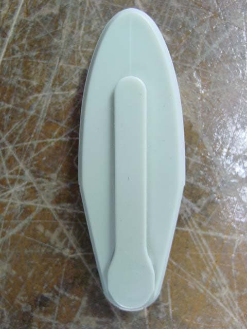
QH7BULLET
Jul 10, 2005USB Flash Drive
Equipment Class
JBP - Part 15 Class B Computing Device Peripheral