QHCCENGPRS1Electricity Meter with GSM/GPRS modem
Itron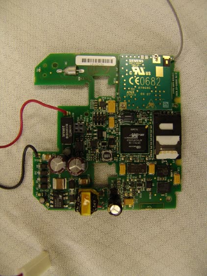
Click to zoom
Application Details
- Equipment Class
- PCB - PCS Licensed Transmitter
- Date of Grant
- Jan 30, 2007
- Application Purpose
- Original Equipment
- Date of Application
- Jan 15, 2007
- Equipment Note
- Electricity Meter with GSM/GPRS modem
- Frequency Range
- 1850.20000000 - 1909.80000000
- Company
- Itron
- Country
- United States
Documents & Files
Document Text
Text extracted from the exhibit documents filed with the FCC. Open a document above to read the original.
Users Manual
www.siemens.com/wm Be inspired Small is beautiful! With MC55/MC56 Siemens mobile presents the world’s smallest, double Tri-Band GSM/GPRS modules! This miniaturized, complete voice- and data solution enables infinite flexibility in the design and creation of next generation’s mobile devices. Opt for MC55/MC56 and convert your ideas into revolutionary solutions for global markets! The application possibilities are virtually unlimited: •Mobile computing devices •Smart phones •Computing accessory cards •And much more to enable your customers wireless connectivity The MC55/MC56 modules are full type approved and optimized for easy and fast integration in mobile devices. Utilizing the MC55/MC56 will reduce your development risk and investment as well as cost and time to market. For contact and more information please visit www.siemens.com/wm MC55/MC56 Wireless Modules Power-up your wireless business At only 3.0 mm, these revolutionary GSM/GPRS modules open up new integration possibilities for a wide spectrum of mobile computing devices, such as PDAs, smart phones and other handhelds. The easy integration path enables a wide range of applications. The MC55/MC56 modules are full type approved for worldwide operation. Siemens MC55/MC56 – the world’s most treasured Tri-Band GSM/GPRS modules: ultra-light, ultra-flat, ultra-flexible. General features: • Tri-Band GSM/GPRS 900/ 1800/1900 MHz (MC55) • Tri-Band GSM/GPRS 850/ 1800/1900 MHz (MC56) • GPRS multi-slot class 10 • GPRS mobile station class B • Compliant to GSM phase 2/2+ • Output power: – 2 W for EGSM850 – 2 W for EGSM900 – 1 W for GSM1800 – 1 W for GSM1900 • Dimensions: 35 x 32.5 x 3.0 mm (btb-connector: 3.3 mm) • Weight: 5.5 g • Control via AT commands (GSM 07.07 and 07.05) • SIM application toolkit • WAP compliant • MMS compliant • Supply voltage range 3.3 ...4.8 V • Low power consumption • Ambient temperature: –20 °C to +55 °C • Auto switch-off at +70 °C Specifications for fax: • Group 3, class 2 Specifications for data: • GPRS class 10: max. 85.6 kbps (downlink) • PBCCH support • Coding schemes CS 1, 2, 3, 4 • CSD up to 14.4 kbps • USSD • Non transparent mode • V.110 • PPP-stack Specifications for SMS via GSM and GPRS: • Point-to-point MO and MT • SMS cell broadcast • Text and PDU mode Specifications for voice: • Tricodec – Half rate (HR) – Full rate (FR) – Enhanced Full rate (EFR) • Adaptive multi rate (AMR) • Hands-free operation (echo cacellation) • Noise reduction Drivers: • Microsoft® Windows Mobile™ RIL Driver • MUX Driver Approvals: • R&TTE • FCC • IC • GCF • PCCRB • Local approvals and mobile operator certifications Interfaces: • Interface to external SIM • Board-to-board connector • Digital and analog audio interfaces • AT commands via serial interface • Two serial interfaces • Power supply 3.3 ...4.8 V • Antenna connector and antenna pad • Battery charger Compatibility: • AT cellular command interface More about Siemens Wireless Modules at: www.siemens.com/wm Copyright 2003, Siemens AG Information and Communication Mobile Wireless Modules Haidenauplatz 1 81667 Munich, Germany Subject to changes in technology, design and availability Order No.: A31001-W25-A218-X-7600 Printed in Germany Wireless Modules Benefits and hard facts Original size
Users Manual
ITRON CENTRON® GPRS SMARTMETER The combination of Itron’s CENTRON® Meter with the GPRS SmartMeter Module from SmartSynch® introduces a powerful residential communication solution for utilities. SmartSynch’s Transaction Management System (TMS™) manages all meters integrated with the SmartMeter module including the CENTRON GPRS SmartMeter. The integrated CENTRON GPRS SmartMeter utilizes ANSI communication standards to retrieve data and events for all the ANSI C12.19-1997 tables and standard manufacturer procedures. Key Functions and Features • Flexible Two-Way Data Retrieval • Scheduled and On-Demand Reads • Automated Interval Read Retrieval • Real-Time Interval Reads • Automated Register, Self-Read and TOU Retrieval • Demand Resets • Real-Time Meter Event and Alarm Retrieval • Real-Time Power Outage and Power Restoration Alarms • Service Diagnostics and Tamper Detection • Tilt Detection • Meter Clock Synchronization • SmartMeter Display Status • Automated Meter Registration • Secure and Encrypted Data Transmissions • Over-The-Air SmartMeter Module Firmware Upgrade Supported Meter Forms • Class 20: 3S, 4S • Class 100: 1S • Class 200: 2S, 12S, 25S • Class 320: 2S Hardware Components • Radio Control Module Board (RCM) • Capacitor Storage Bank (CSB) • GSM Modem (Siemens MC56) • Internal Antenna • Tilt Detector • Temperature Sensor Operating Ranges Temperature • Operating: [-40°C, +85°C] • Transmission (wireless): [-40°C, +80°C] Humidity • 0% to 95% non-condensing Accuracy • Meets ANSI 12.20 for accuracy class 0.5% Regulatory and Industry Specifications • FCC Part 15 Class B • FCC Part 90 and FCC Part 1 (MPE) • ANSI C37.90.1 - 1989: (SWC) • ANSI C12.20 (Class 0.5) – 1998 • PTCRB approval (in process) SmartSynch, Inc. 1-888-362-1780 www.smartsynch.com ITRON CENTRON® GPRS SMARTMETER Functions and Features Flexible Two-way DaTa ReTRieval anD ScheDuleD DaTa collecTion Users can execute all appropriate TMS functionality using user configurable SmartMeter controlled schedules and TMS controlled schedules and as well as on an on-demand basis. auTomaTeD inTeRval DaTa/eneRgy uSage ReTRieval The CENTRON GPRS SmartMeter module retrieves and transmits interval data for 1 unique energy value for intervals as small as 5 minutes. Recorded events and exceptions with each interval are also transmitted to the TMS, which interprets them and logs appropriate messages (e.g. time adjustments). Real-Time inTeRval ReaDS Real-time interval data acquisition enables utilities to implement Load Curtailment and Real Time Pricing (RTP) programs. With this functionality, the user can configure the SmartMeter module to transmit load profile data as often as every 15 minutes at interval completion. auTomaTeD RegiSTeR, SelF-ReaD anD Tou ReTRieval The CENTRON GPRS SmartMeter module is configured by the TMS to read and transmit all or a subset of enabled registers including totals, self-reads, maximum demand and time-of-use values. DemanD ReSeTS The CENTRON GPRS SmartMeter module executes Demand Resets using one of three methods: SmartModule initiated schedules, TMS initiated schedules or TMS on-demand requests. Real-Time meTeR evenT anD alaRm ReTRieval The CENTRON GPRS SmartMeter provides automatic real-time alarm reporting of all events defined in the ANSI C12.19 standard including history and event codes, ANSI Standard status and Manufacturer status alarms. Additionally, alarms received by TMS can be automatically routed via e-mail to a specific user or group of users using the TMS Message Routing Interface. Real-Time PoweR ouTage anD ReSToRaTion alaRmS With built-in Ultra Capacitor energy storage, the CENTRON GPRS SmartMeter module will transmit a real time “last gasp” notification when detecting an AC power outage without requiring the use of less reliable batteries. The CENTRON GPRS SmartMeter also notifies the TMS when the AC power is restored and provides full configuration of these alarms based on user defined durations. SeRvice DiagnoSTic anD TamPeR DeTecTion aleRTS The CENTRON GPRS SmartMeter can report power service and wiring errors detected by the meter including reverse polar- ity, cross-phase and energy flow, phase voltage deviation, inactive phase current, phase angle displacement, and current waveform distortion. In addition, the SmartMeter can detect and report exceptions for the following tamper events: number of Demand Resets, Loss of AC power, and reported power outages. The TMS configures a specific filter in the SmartMeter for each of these events enabling the transmission of a corresponding alert only after the event is repeated a minimum of times within a specific duration. The TMS can also configure the SmartMeter to reset the event counter when the alert message is transmitted. TilT DeTecTion The CENTRON GPRS SmartMeter can detect and report tilt events that occur when the SmartMeter is moved from its installation position. meTeR clock SynchRonizaTion If enabled, the SmartModule automatically adjusts the meter clock when the time deviation falls within user-defined lower and upper deviation boundaries based on a reference clock provided by the TMS. If the deviation exceeds the upper boundary, the module reports the deviation via an alarm but does not correct the meter clock. If the deviation is less than the lower boundary, the module ignores the deviation. SmaRTmeTeR STaTuS DiSPlay The CENTRON GPRS SmartMeter supports an optional LCD status sequence to display important SmartMeter indicators periodically. This status sequence includes the meter site coverage status, SmartModule firmware state and any SmartModule firmware warnings/errors enabling technicians to ensure proper installation of the CENTRON GPRS SmartMeters and allow field troubleshooting without any other tools. auTomaTeD meTeR RegiSTRaTion The SmartMeter module automatically transmits a registration message to the TMS when the meter is installed without requiring user intervention. This message permits the TMS to create or update the met…
Text truncated - open the document above for the full version.
Users Manual
© 2006 SmartSynch™ SmartMeter™ System Itron CENTRON ® GPRS SmartMeter User Guide SMR45-4601A CENTRON GPRS SmartMeter User Guide SMR45-4601A 2 Copyrights Copyright 2006 SmartSynch ® , Inc. All rights reserved. No part of this documentation may be reproduced transmitted, processed, or recorded by any means or form, or be released to any third party without the express written consent of SmartSynch, Inc. Trademarks SmartSynch ® , SmartSynch logo, TMS™, and SmartMeter™ are trademarks or registered trademarks of SmartSynch, Inc. All other companies, brands, and product names listed herein are trademarks or registered trademarks of their respective holders. Document Revisions The CENTRON SmartMeter User Guide can be referred to by its document number: SMR45-4601A. Each revision of this document is designated with a letter, beginning with “A”. SmartSynch, Inc. reserves the right to revise this publication and to make any modifications to its content, at any time, without obligation to notify any party, person, or entity of such revisions or changes. Occasionally, changes or variations exist in the products that are not reflected in the documentation. Generally, if such changes or variations are known to exist and affect the product significantly, release notes will accompany the documentation. The information in this guide should not be considered as all-inclusive or covering all cases for events that may occur. If further information is required, consult your technical support representative. See the License Agreement contained in the product for complete license information. Contact your technical support representative for more information on any of our products. CENTRON GPRS SmartMeter User Guide SMR45-4601A 3 Table of Contents 1 INTRODUCTION...............................................................................................................................................5 1.1 ABOUT THIS GUIDE........................................................................................................................................5 1.2 REFERENCE MATERIALS.................................................................................................................................5 1.3 CONTACTING SMARTSYNCH...........................................................................................................................5 1.3.1 Technical Support..................................................................................................................................5 1.3.2 Documentation Feedback......................................................................................................................6 1.3.3 SmartSynch Headquarters.....................................................................................................................6 2 GETTING STARTED.........................................................................................................................................7 2.1 OPERATIONS...................................................................................................................................................7 2.2 SAFETY PRECAUTIONS....................................................................................................................................7 2.2.1 Interference with Medical Equipment....................................................................................................7 2.2.2 Fire or Explosion Hazards....................................................................................................................7 2.2.3 Interference with Other Devices............................................................................................................8 2.3 PREREQUISITES...............................................................................................................................................8 3 INSTALLING THE CENTRON SMARTMETER..........................................................................................9 3.1 PRELIMINARY INSPECTIONS............................................................................................................................9 3.2 INSTALLATION PROCESS.................................................................................................................................9 3.2.1 Option 1: Direct Field Installation........................................................................................................9 3.2.2 Option 2: Meter Shop Test and Field Installation.................................................................................9 3.2.3 Meter Installation..................................................................................................................................9 3.3 PROVISIONING THE SMARTMETER...............................................................................................................10 4 TROUBLESHOOTING....................................................................................................................................11 4.1 TROUBLESHOOTING PROCESS FLOW............................................................................................................11 4.2 TROUBLESHOOTING PROCESS DESCRIPTION.................................................................................................12 5 CENTRON DISPLAY FEATURE...................................................................................................................14 6 REQUIREMENTS AND COMPLIANCE......................................................................................................16 CENTRON GPRS SmartMeter User Guide SMR45-4601A 5 1 Introduction 1.1 About This Guide This document is a manual designed to help guide you through the testing, installation and activation of your Itron CENTRON ® SmartMeter. This manual provides general instructions on the support of your SmartMeter and references to supporting manufacturer documentation for detaile…
Text truncated - open the document above for the full version.
Cover Letter(s)
Federal Communications Commission Date: November 21, 2006 Equipment Authorization Branch 7435 Oakland Mills Road Columbia, MD 21046 Dear Sir or Madam: Itron, Inc. respectfully requests confidentiality of certain Itron information provided with the submission of the SmartSynch GPRS modem under FCC ID: QHC-CENGPRS1 in accordance with FCC Regulations 0.459. The confidentiality request applies to the parts list, schematics, and block diagrams supplied by Itron for use with the SmartSynch product approval. The Itron CENTRON D/T/L meter has been developed at considerable effort and expense by Itron, Inc. These items are considered as trade secrets and therefore public access to the proprietary material could possibly result in duplication of equipment that could severely damage the company's business advantage. I appreciate your assistance in this matter. Sincerely, Name: Lee Littlejohn Signature: Title: Regulatory Engineer Date: November 21, 2006
Cover Letter(s)
November 27, 2006 Letter of Authorization To whom it may concern, We the undersigned, hereby authorize CETECOM Inc. (411 Dixon Landing Road, Milpitas, CA 95035, Tel.408 586 6214) to act on our behalf in all manners relating to application for equipment authorization, including signing of all documents relating to these matters. Any and all acts carried out by CETECOM Inc., on our behalf shall have the same effect as acts of our own. This authorization from SmartSynch, Inc. is valid until further notice for all documents relating to equipment authorization for the Centron GPRS electricity meter. Sincerely, R. Bryan Seal Vice President, Engineering SmartSynch, Inc. 4400 Old Canton Road Suite 300 Jackson, MS 39211
Cover Letter(s)
Federal Communication Commission Equipment Authorization Division, Application Processing Branch 7435 Oakland Mills Road Columbia, MD 21048 November 27, 2006 TO WHOM IT MAY CONCERN Pursuant to Paragraphs §0.457 and 0.459 of the Commission’s Rules (47 C.F.R.) and Section §552(b)(4) of the Freedom of Information Act, SmartSynch, Inc. requests confidentiality for the following products: FCC ID Number Product Title/Model QHC-CENGPRS1 Itron/Centron GPRS Electricity Meter For the product stated above, we request that the following information be held confidential: 1) Electrical Schematics of the Circuitry 2) Block Diagram 3) Parts List 4) Operational Description No other items submitted as part of the equipment authorization filing process are deemed confidential. The above exhibits contain SmartSynch, Inc. trade secrets and proprietary information that could be of benefit to our competitors regarding the design of our mobile handset. This material is not customarily available to the general public and we request that it be withheld from public inspection. If you have any questions, please feel free to contact me at the address shown below. Sincerely, R. Bryan Seal Vice President, Engineering SmartSynch, Inc. 4400 Old Canton Road Suite 300 Jackson, MS 39211
Cover Letter(s)
Federal Communication Commission Equipment Authorization Division, Application Processing Branch 7435 Oakland Mills Road Columbia, MD 21048 January 9, 2007 TO WHOM IT MAY CONCERN Request for Confidentiality as Described in FCC DA 04-1705 FCC-ID : QHC-CENGPRS1 Please be advised that the following information is to be held confidential and behalf of SmartSynch, Inc. until the date April 9, 2007. - Photographs - User Manual - Block Diagrams The application contains technical information which SmartSynch, Inc. deems to be trade secrets and proprietary. If made public. the information might be used to the advantage of the applicant in the market place. Sincerely, R. Bryan Seal Vice President, Engineering SmartSynch, Inc. 4400 Old Canton Road Suite 300 Jackson, MS 39211
External Photos
FCC Grant Application Photographs For the Itron CENTRON ® SmartSynch-Enabled SmartMeter FCC ID: QHC-CENGPRS1 IC ID: 4393B-CENGPRS1 11/28/2006 Prepared By: 4400 Old Canton Rd. Suite 300 Jackson, MS 39211 11/28/2006 1 Figure 1: Itron CENTRON SmartSynch-Enabled SmartMeter Figure 2: FCC and IC Label Examples – Located Above LCD Display FCC and IC Label Location 11/28/2006 2 Figure 3: Flexible Dipole Antenna Location Figure 4: Outer Cover and Bezel Removed, Revealing Antenna Location and Internal Electronics Antenna Lead Flexible Dipole Antenna Antenna Penetration Through Bezel 11/28/2006 3 Figure 5: FCC Labeling Example Figure 6: Inside View of Flexible Dipole Antenna Penetration through the Bezel, with Attached Antenna Lead 11/28/2006 4 Figure 7: Itron Register and Display Board – Front View Figure 8: Itron Register and Display Board – Back View 11/28/2006 5 Figure 9: Itron Register and Display Board Removed, Revealing SmartSynch Module Board Underneath Figure 10: Antenna Lead Connection to Siemens MC-56 Modem on SmartSynch Module Board Capacitor Bank Board (CBB) on Top of SmartSynch Module Board SIM Card Socket 11/28/2006 6 Figure 11: SmartSynch Module Board – Front View Figure 12: SmartSynch Module Board – Back View 11/28/2006 7 Figure 13: SmartSynch Module Board – Capacitor Bank Board (CBB) Removed, Revealing Siemens MC-56 Modem Underneath Siemens MC-56 Modem Antenna Lead 11/28/2006 8 Figure 14: SmartSynch Capacitor Bank Board (CCB) – Front View Figure 15: SmartSynch Capacitor Bank Board (CBB) – Back View 11/28/2006 9 Figure 16: SmartSynch Module Board Removed, Revealing Itron Main Meter Board Underneath
Internal Photos
FCC Grant Application Photographs For the Itron CENTRON ® SmartSynch-Enabled SmartMeter FCC ID: QHC-CENGPRS1 IC ID: 4393B-CENGPRS1 11/28/2006 Prepared By: 4400 Old Canton Rd. Suite 300 Jackson, MS 39211 11/28/2006 1 Figure 1: Itron CENTRON SmartSynch-Enabled SmartMeter Figure 2: FCC and IC Label Examples – Located Above LCD Display FCC and IC Label Location 11/28/2006 2 Figure 3: Flexible Dipole Antenna Location Figure 4: Outer Cover and Bezel Removed, Revealing Antenna Location and Internal Electronics Antenna Lead Flexible Dipole Antenna Antenna Penetration Through Bezel 11/28/2006 3 Figure 5: FCC Labeling Example Figure 6: Inside View of Flexible Dipole Antenna Penetration through the Bezel, with Attached Antenna Lead 11/28/2006 4 Figure 7: Itron Register and Display Board – Front View Figure 8: Itron Register and Display Board – Back View 11/28/2006 5 Figure 9: Itron Register and Display Board Removed, Revealing SmartSynch Module Board Underneath Figure 10: Antenna Lead Connection to Siemens MC-56 Modem on SmartSynch Module Board Capacitor Bank Board (CBB) on Top of SmartSynch Module Board SIM Card Socket 11/28/2006 6 Figure 11: SmartSynch Module Board – Front View Figure 12: SmartSynch Module Board – Back View 11/28/2006 7 Figure 13: SmartSynch Module Board – Capacitor Bank Board (CBB) Removed, Revealing Siemens MC-56 Modem Underneath Siemens MC-56 Modem Antenna Lead 11/28/2006 8 Figure 14: SmartSynch Capacitor Bank Board (CCB) – Front View Figure 15: SmartSynch Capacitor Bank Board (CBB) – Back View 11/28/2006 9 Figure 16: SmartSynch Module Board Removed, Revealing Itron Main Meter Board Underneath
Test Report
Bluetooth Qualification Test Facility (BQTF) FCC listed# 101450 IC recognized # 3925 CETECOM Inc. 411 Dixon Landing Road Milpitas, CA 95035 U.S.A. Phone: + 1 (408) 586 6200 Fax: + 1 (408) 586 6299 E-mail: [email protected] http://www.cetecom.com CETECOM Inc. is a Delaware Corporation with Corporation number: 2113686 Board of Directors: Dr. Harald Ansorge, Dr. Klaus Matkey, Hans Peter May V1.1 2003-03-01 The BLUETOOTH trademarks are owned by Bluetooth SIG, Inc., U.S.A. and licensed to CETECOM Inc. © Copyright by CETECOM FCC Test Report FCC Part 22,24 / RSS 132,133 FOR: Electricity Meter with GSM/GPRS MODEL #: Centron GPRS SmartSynch Inc. 3010 Lakeland Cove East Pointe Business Park, Suite S Flowood. MS 39232 USA FCC ID: QHC-CENGPRS1 IC-ID : 4393B-CENGPRS1 TEST REPORT #: EMC_ SMAR1_002_06502 _FCC22_24 DATE: 2006-10-23 Test Report #: EMC_SMAR1_002_06502 FCC22-24 Date of Report: 2006-10-23 Page 2 of 52 This report shall not be reproduced except in full without the written approval of: CETECOM, Inc. Table of Contents 1 ASSESSMENT .................................................................................................................................... 3 2 ADMINISTRATIVE DATA............................................................................................................... 4 2.1 IDENTIFICATION OF THE TESTING LABORATORY ISSUING THE EMC TEST REPORT..................... 4 2.2 IDENTIFICATION OF THE CLIENT................................................................................................... 4 2.3 IDENTIFICATION OF THE MANUFACTURER.................................................................................... 4 3 EQUIPMENT UNDER TEST (EUT) ................................................................................................ 5 3.1 IDENTIFICATION OF THE EQUIPMENT UNDER TEST....................................................................... 5 3.2 IDENTIFICATION OF ACCESSORY EQUIPMENT............................................................................... 5 4 SUBJECT OF INVESTIGATION..................................................................................................... 6 5 MEASUREMENTS............................................................................................................................. 7 5.1 RF POWER OUTPUT....................................................................................................................... 7 5.1.1 FCC 2.1046 Measurements required: RF power output....................................................... 7 5.1.2 Limits: ................................................................................................................................... 7 5.1.2.1 FCC 22.913 (a) Effective radiated power limits. .............................................................. 7 5.1.2.2 FCC 24.232 (b)(c) Power limits. ....................................................................................... 7 5.1.3 Radiated Output Power Measurement procedure:................................................................ 8 5.1.4 ERP Results 850 MHz band: ................................................................................................. 9 5.1.5 EIRP Results 1900 MHz band:.............................................................................................. 9 5.2 SPURIOUS EMISSIONS RADIATED................................................................................................ 16 5.2.1 FCC 2.1053 Measurements required: Field strength of spurious radiation....................... 16 5.2.2 Limits: ................................................................................................................................. 16 5.2.2.1 FCC 22.917 Emission limitations for cellular equipment. ............................................. 16 5.2.2.2 FCC 24.238 Emission limitations for Broadband PCS equipment. ............................... 16 5.2.3 Radiated out of band measurement procedure: .................................................................. 17 5.2.4 Radiated out of band emissions results on EUT: ................................................................ 19 5.2.4.1 RESULTS OF RADIATED TESTS GSM-850: ............................................................. 19 5.2.4.2 RADIATED SPURIOUS EMISSIONS (GSM-850)....................................................... 20 5.2.4.3 RESULTS OF RADIATED TESTS PCS-1900: ............................................................. 30 5.2.4.4 RADIATED SPURIOUS EMISSIONS(PCS 1900) ....................................................... 31 5.3 RECEIVER RADIATED EMISSIONS § 2.1053 / RSS-132 & 133 ......................................... 39 5.3.1 Receiver Spurious on EUT 850 MHz .................................................................................. 40 5.3.2 Receiver Spurious on EUT 1900 MHz ................................................................................ 43 5.4 AC POWER LINE CONDUCTED EMISSIONS § 15.107/207.................................................. 47 5.4.1 LIMITS ................................................................................................................................ 47 5.4.2 RESULTS............................................................................................................................. 48 6 TEST EQUIPMENT AND ANCILLARIES USED FOR TESTS ................................................ 49 7 REFERENCES .................................................................................................................................. 50 8 BLOCK DIAGRAMS ....................................................................................................................... 51 Test Report #: EMC_SMAR1_002_06502 FCC22-24 Date of Report: 2006-10-23 Page 3 of 52 This report shall not be reproduced except in full without the written approval of: CETECOM, Inc. 1 Assessment The following is in compliance with the applicable criteri…
Text truncated - open the document above for the full version.
Test Report
CETECOM ICT Services GmbH Radio Satellite Communication Untertürkheimer Straße 6-10 . D-66117 SaarbrückenTelefon: +49 (0)681 598-9100Telefax: -9075 RSC11Issued test report consists of 97 pagesPage 1 (97) BLUETOOTH TM is a trademark owned by Bluetooth SIG, Inc. and licensed to CETECOM Recognized by the Federal Communications Commission Anechoic chamber registration no.: 90462 (FCC) Anechoic chamber registration no.: 3463 (IC) TCB ID: DE 0001 Accredited by the German Accreditation Council DAR–Registration Number TTI–P–G 166/98 Independent ETSI compliance test house ETSI Accredited Bluetooth™ Test Facility (BQTF) Test report no.: 2_3450-01-01/03 FCC Part 24/22/15 MC56 FCC ID: QIPMC56 IC: 267W-MC56 CETECOM – ICT Services GmbH Untertürkheimerstr. 6-10 66117 Saarbrücken, Germany Telephone: + 49 (0) 681 / 598-0 Fax: + 49 (0) 681 / 598-9075 CETECOM ICT Services GmbH Test report no..: 2_3450-01-01/03Issue Date: 2003-12-12Page 2 (97) Table of Contents 1 General information 1.1 Notes 1.2 Testing laboratory 1.3 Details of applicant 1.4 Application details 1.5 Test item 1.6 Test standards 2 Technical test 2.1 Summary of test results 2.2 Test report 1 General information 1.1 Notes The test results of this test report relate exclusively to the test item specified in 1.5. The CETECOM ICT Services GmbH does not assume responsibility for any conclusions and generalizations drawn from the test results with regard to other specimens or samples of the type of the equipment represented by the test item. The test report may only be reproduced or published in full. Reproduction or publication of extracts from the report requires the prior written approval of the CETECOM ICT Services GmbH. 1.2Testing laboratory CETECOM ICT Services GmbH Untertürkheimer Stra…
Text truncated - open the document above for the full version.
Contact Information
Applicant
Mike Mathis(Senior Compliance Engineer)
Technical Contact
CETECOM Inc.Lothar Schmidt
[email protected]408-586-6214
411 Dixon Landing Rd. · Milpitas, California · United States
Test Firm
CETECOM GmbHWolfgang Richter
Technical Specifications
| # | Rule Parts | Frequency Range | Power Output | Emission | Tolerance |
|---|---|---|---|---|---|
| 2 | 24E | 1.85 GHz - 1.91 GHz | 1.923 W | 291GXW | 0.016 ppm |
Other Applications from Itron

QHC-OW35PE
Aug 17, 2015OpenWay 3.5P
Equipment Class
DSS - Part 15 Spread Spectrum Transmitter
QHC-OW35SE
Apr 21, 2015OpenWay 3.5S
Equipment Class
DSS - Part 15 Spread Spectrum TransmitterQHC-KVEVZE41
Jun 19, 2014kV2c-AMPZE Module
Equipment Class
DTS - Digital Transmission SystemQHC-060203A
Dec 15, 2013OpenWay 3.1 Module
Equipment Class
DSS - Part 15 Spread Spectrum Transmitter
QHC-010201A
Jan 07, 2013SmartSynch Interface Module
Equipment Class
DTS - Digital Transmission System