QI2-EMSGRF Intelliway Gateway
Robertshaw Controls Company d/b/a Invensys Home Control Systems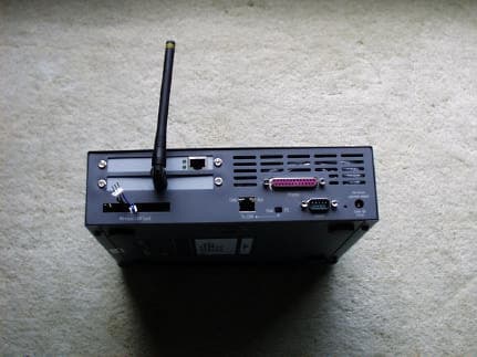
Click to zoom
Application Details
- Equipment Class
- DSS - Part 15 Spread Spectrum Transmitter
- Date of Grant
- Aug 07, 2002
- Application Purpose
- Original Equipment
- Date of Application
- Aug 07, 2002
- Equipment Note
- RF Intelliway Gateway
- Frequency Range
- 905.00000000 - 924.60000000
- Country
- United States
Documents & Files
Document Text
Text extracted from the exhibit documents filed with the FCC. Open a document above to read the original.
Users Manual
TD2002-EVXCOPYRIGHT © 2002 INVENYS HOME CONTROL SYSTEMS8/5/02 EMSG Intelliway RF Gateway General Instructions Introduction The Intelliway RF Gateway is a high performance wireless broadband server that is a central part of the Invensys GoodWatts system. In addition to basic product description, this document provides specifications and specific instructions for setup. Note:This equipment has been tested and found to comply with the limits for a Class B digital device, pursuant to Part 15 of the FCC Rules. These limits are designed to provide reasonable protection against harmful interference in a residential installation. This equipment generates, uses and can radiate radio frequency energy and, if not installed and used in accordance with the instructions, may cause harmful interference to radio communications. However, there is no guarantee that interference will not occur in a particular installation. If this equipment does cause harmful interference to radio or television reception, which can be determined by turning the equipment off and on, the user is encouraged to try to correct the interference by one or more of the following measures: – Reorient or relocate the receiving antenna. – Increase the separation between the equipment and receiver. – Connect the equipment into an outlet on a circuit different from that to which the receiver is connected. – Consult the dealer or an experienced radio/TV technician for help. Caution:This equipment is authorized for use under the United States Federal Communication Commission Rules and Regulations, Code of Federal Regulations Chapter 47 part 15 and must be installed in accordance with the instructions provided in this document. Failure to install or operate this equipment as instructed in this document could void the user’s authority to operate the equipment. This equipment contains no user serviceable parts. Any modification or repairs to the internal components or to the antenna configuration of the equipment without the express written consent of Invensys Home Control Systems could void the user's authority to operate the equipment. FIGURE 1.Intelliway RF Gateway Note:To comply with FCC RF exposure requirements in section 1.1307, a minimum separation distance of 20 cm (8 inches) is required between the antenna and all persons. Inspection Inspect the product carton for damage. If damaged, notify carrier immediately. Inspect the Intelliway RF Gateway for damage. Return damaged products. Check that the contents includes all components, as listed below and shown in FIGURE 2. Intelliway RF Gateway Components : – Intelliway server – Power adapter – RJ-45 ethernet cable INTELLIWAY RF GATEWAYGENERAL INSTRUCTIONS 2PRELIMINARY DOCUMENTTD2002-EVX FIGURE 2.Intelliway RF Gateway Components Installation Location The Intelliway RF Gateway is an Energy Star compliant low power consumption, “always-on” server appliance. Proper location and setup of the device is essential for achieving top performance and longevity. The Intelliway RF Gateway should be situated in a clean, flat, stable, open environment with adequate ventilation and isolated from any forms of moisture, dust and contaminates. Placement of the device on or near a desktop or industrial shelving is recommended, however, placement within a wiring closet or wall mounting (professional installation recommended) are also viable alternatives. Connections The following sections provide instructions for connecting to the Internet and the procedural steps for applying power to the gateway. Internet connection FIGURE 3.Intelliway RF Gateway connections Note:Be careful to avoid reversing the WAN and LAN connections. The Intelliway RF Gateway connector is located on the upper part of the back panel. GENERAL INSTRUCTIONSCONNECTING POWER 8/5/02PRELIMINARY DOCUMENT3 1. Refer to FIGURE 3. Intelliway RF Gateway connections, and connect your external Cable to the Intelliway RF Gateway with an Ethernet cable (supplied by your modem manufacturer). 2. Turn on your external Cable modem. Connecting Power Note:There is NO power switch located on the Intelliway RF Gateway unit. The unit is “on” when you plug it in to a power outlet. Turning the gateway “off” is controlled via the gateway software or by unplugging the power adapter. 1. Plug the supplied power adaptor into the DC connector on the back of the Intelliway RF Gateway and insert the power plug into a wall socket with surge protection. 2. The Intelliway RF Gateway will automatically run a 2-3 minute sequential self-test. The LED light located on the front of the gateway will indicate the status of the process, starting from a green blinking light through a solid green light if every test passes. Note:You may see a very subtle orange blinking over the Solid Green light when the data is processing 3. Follow the LED readouts and proceed accordingly. Refer to TABLE 1. LED indicator descriptions for a listing of light indications. TABLE 1. LED indicator descriptions Operation The Intelliway RF Gateway is pre-configured to automatically use the WAN interface for connecting to the GoodWatts.com server. After a connection is made, the home-specific information is downloaded into the gateway and the RF device network is started, as shown in FIGURE 4. GoodWatts RF device network. FIGURE 4.GoodWatts RF device network LED StatusIndicationAction Green Blinking (1 blink)Process basic hardware testingWait for LED status change Green Blinking (2 blinks) Process extensive hardware testingWait for LED status change Green Blinking (3 blinks) Process software testingWait for LED status change Green Blinking (4 blinks) Indicates Internet (WAN) connection needs configuration via Intelliway RF Gateway software Contact Technical Support Solid Green lightIndicates Internet (WAN) connectivity is complete No action necessary Red BlinkingAn internal failure has occurredContact technical support Gateway Thermostat Meter Load ControlMeter TD2002-EVXINTELLIWAY RF GATEWAYPRINTED IN U.S.A…
Text truncated - open the document above for the full version.
Cover Letter(s)
tel: 650-726-1263 fax: 650-726-1252 [email protected] Thomas N. Cokenias EMC &Radio Approvals Test & Consulting Services for Commercial, Military, International Compliance P.O. Box 1086 El Granada, CA 94018 FCC Laboratory31 July 2002 7435 Oakland Mills Road Columbia, MD 21046 Attention: Application Examiner Reviewing Engineer Applicant: Invensys Home Control Systems FCC ID: QI2-EMSG Intelliway RF Gateway To whom it may concern, Request is hereby submitted, on behalf of my client Invensy HCS to withhold from public review certain portions of the application for equipment certification for the referenced FCC identifier. In particular, the following sections of the application and report are requested to be kept confidential: Block Diagrams Schematic Operational Description Rationale for request for confidentiality: Invensys has invested considerable time and materials in research and development to produce the referenced product. Disclosure of the confidential portions of this application to competitors would give them competitive advantage in developing similar products. If you have questions or need further information, please contact the undersigned. Sincerely, tel: 650-726-1263 fax: 650-726-1252 [email protected] THOMAS N. COKENIAS EMC Consultant/Agent for Robershaw Control Systems (dba Invensys Home Control systems)
External Photos
FCC ID: QI2-EMSG Invensys Intelliway Gateway FCC ID: QI2-EMSG FCC ID: QI2-EMSG
ID Label/Location Info
FCC Label/Location FCC ID: QI2-EMSG This device complies with Part 15 of the FCC Rules. Operation is subject to the following two conditions: (1) This device may not cause harmful interference, and (2) This device must accept any interference received, including interference than may cause undesired operation
Internal Photos
FCC ID: QI2-EMSG FCC ID: QI2-EMSG FCC ID: QI2-EMSG FCC ID: QI2-EMSG FCC ID: QI2-EMSG FCC ID: QI2-EMSG FCC ID: QI2-EMSG FCC ID: QI2-EMSG FCC ID: QI2-EMSG FCC ID: QI2-EMSG FCC ID: QI2-EMSG FCC ID: QI2-EMSG Radio board top side FCC ID: QI2-EMSG Radio board bottom FCC ID: QI2-EMSG Under radio board FCC ID: QI2-EMSG FCC ID: QI2-EMSG
Parts List/Tune Up Info
Antenna The picture shows the rotation axis Receiving antenna Date July_9_2002 Test location SB AUT antenna Operator C.Paun Z Frequency 914MHz Spectrum Distance 3.55m analyzer Signal souce, TX output power 3.80dBm battery powered Cable loss 0.60dB Path loss 42.67dB RX antenna gain 7.14dB System loss -33.33dB VSWR at 914MHz 2.00 Y Rotating gear, encoder Correction -0.51 X Zo 50.00ohm The grey fields are for input dataAUT rotation axis Everex_A1 Everex_A2 Angle spectrum Everex_A1 spectrum Everex_A2 0.00deg -34.80dBm -0.96dBi -34.40dBm -0.56dBi 11.25deg -34.35dBm -0.51dBi -33.90dBm -0.06dBi 22.50deg -33.90dBm -0.06dBi -33.40dBm 0.44dBi 33.75deg -33.55dBm 0.29dBi -32.90dBm 0.94dBi 45.00deg -33.20dBm 0.64dBi -32.40dBm 1.44dBi 56.25deg -32.95dBm 0.89dBi -32.15dBm 1.69dBi 67.50deg -32.70dBm 1.14dBi -31.90dBm 1.94dBi 78.75deg -32.65dBm 1.19dBi -31.85dBm 1.99dBi 90.00deg -32.60dBm 1.24dBi -31.80dBm 2.04dBi 101.25deg -32.65dBm 1.19dBi -31.80dBm 2.04dBi 112.50deg -32.70dBm 1.14dBi -31.80dBm 2.04dBi 123.75deg -33.00dBm 0.84dBi -32.10dBm 1.74dBi 135.00deg -33.30dBm 0.54dBi -32.40dBm 1.44dBi 146.25deg -33.80dBm 0.04dBi -32.85dBm 0.99dBi 157.50deg -34.30dBm -0.46dBi -33.30dBm 0.54dBi 168.75deg -34.90dBm -1.06dBi -33.95dBm -0.11dBi 180.00deg -35.50dBm -1.66dBi -34.60dBm -0.76dBi 191.25deg -36.20dBm -2.36dBi -35.25dBm -1.41dBi 202.50deg -36.90dBm -3.06dBi -35.90dBm -2.06dBi 213.75deg -37.50dBm -3.66dBi -36.40dBm -2.56dBi 225.00deg -38.10dBm -4.26dBi -36.90dBm -3.06dBi 236.25deg -38.35dBm -4.51dBi -37.10dBm -3.26dBi 247.50deg -38.60dBm -4.76dBi -37.30dBm -3.46dBi 258.75deg -38.50dBm -4.66dBi -37.20dBm -3.36dBi 270.00deg -38.40dBm -4.56dBi -37.10dBm -3.26dBi 281.25deg -38.00dBm -4.16dBi -36.80dBm -2.96dBi 292.50deg -37.60dBm -3.76dBi -36.50dBm -2.66dBi 303.75deg -37.05dBm -3.21dBi -36.05dBm -2.21dBi 315.00deg -36.50dBm -2.66dBi -35.60dBm -1.76dBi 326.25deg -36.10dBm -2.26dBi -35.25dBm -1.41dBi 337.50deg -35.70dBm -1.86dBi -34.90dBm -1.06dBi 348.75deg -35.25dBm -1.41dBi -34.65dBm -0.81dBi Gain Average -0.95dBi Average -0.06dBi Peak 1.24dBi Peak 2.04dBi dBi -25-20-15-10 -5 05 Everex_A1 Everex_A2
RF Exposure Info
FCC ID: QI2-EMSG Invensys HCS Intelliway Gateway 16 of 16 900MHz FHSS RF Exposure (MPE) Calculations 905 - 924.6 MHz Frequency Hopping Spread Spectrum Radio Applicant: Robertshaw Controls Company FCC ID: QI2-EMSG RF Hazard Distance Calculation (worst case) mW/cm2 from Table1:0.60 Max RF PowerTX AntennaMPE P, dBmG, dBiSafe Distance, cm 13.32.042.13 Basis of Calculations: E^2/3770 = S, mW/cm2 E, V/m = (Pwatts*Ggain*30)^.5/d, meters d = ((Pwatts*G*30)/3770*S))^0.5Pwatts*Ggain = 10^(PdBm-30+GdBi)/10) NOTE: For mobile or fixed location transmitters, minimum separation distance is 20 cm, even if calculations indicate MPE distance is less
Test Report
FCC ID: QI2-EMSG Invensys HCS Intelliway Gateway 1 of 16 900MHz FHSS EMISSIONS TEST REPORT FOR A LOW POWER TRANSMITTER I. GENERAL INFORMATION Requirement:Federal Communications Commissions Test Requirements: 15.205, 15.207, 15.209, 15.247 Applicant: Robertshaw Controls Company d/b/a Invensys Home Control Systems Product ID: FCC ID: QI2-EMSG II. DESCRIPTION OF EQUIPMENT UNDER TEST (EUT) The Invensys “RF IntelliWAY Gateway” unit utilizes an iCon OEM transceiver module to communicate between r.f. modules and a LAN within the home. This allows the user to control home appliances (e.g. climate control devices) from any place where there is a computer connected to the LAN. The OEM Transceiver Module operates in the U.S. ISM band between 902 and 928 MHz. The module incorporates a microcontroller and an r.f. integrated circuit that form a frequency hopping spread spectrum transceiver operating under FCC part 15.247. Transmitter Specification TX Power12dBm Frequency Deviation (FSK)+/- 20 kHz Frequency of operation905 – 924.6 MHz Data Rate19.2 kbps Number of channels50 Channel Separation400 kHz Typical 20dB occupied bandwidth 150 kHz III. TEST LOCATION All tests were performed at: Compliance Certification Services 561F Monterey Road Morgan Hill, CA 95037 T.N. Cokenias29 July 2002 EMC Consultant/Agent for Invensys FCC ID: QI2-EMSG Invensys HCS Intelliway Gateway 2 of 16 900MHz FHSS 15.203 Antenna connector requirement The antenna is permanently attached to the product. 15.204 Antenna description The Intelliway Gateway uses a permanently attached antenna: Antenna descriptionGainMFR name monopole2.04 dBi maxEverex A2 Measured antenna data and radiation patterns are presented in a separate pdf attachment. 15.247(a) Frequency hopping spread spectrum definition Pseudorandom frequency hopping sequence: The transmitter cannot coordinate its hopping sequence with the hopping sequence of other transmitters, or vice versa, for the purpose of avoiding the simultaneous occupancy of individual hopping frequencies by multiple transmitters Each access unit has an individual ID number and there is no link or association between two access units so there is no simultaneous occupancy of individual hopping frequency transmission of two or more access units. Equal hopping frequency use: The EUT utilizes 50 hopping channels. Hopset is 50 channels long, then repeats. On average all channels are used equally. System receiver input bandwidth and receiver hopping capability: Receiver 26 dB bandwidth is 200 kHz, approximately equal to 26 dB bandwidth of TX. Receiver channel hops are synchronized to transmitter operating frequency. FCC ID: QI2-EMSG Invensys HCS Intelliway Gateway 3 of 16 900MHz FHSS TEST DATA and TEST PROCEDURES - CCS Laboratory Radiated Emissions Test Requirement: 15.205, 15.247 Out of Band Measurements Test Requirement: 15.247 Measurement Equipment Used: HP 8566 Spectrum Analyzer, 30-1000 MHz GHz HP 8447D Pre-amplifier, .1 - 1300 MHz Schaffner/Chase CBL6112B Bilog Antenna, 30 - 2000 MHz HP 8593EM Spectrum Analyzer, 1 - 9.5 GHz Miteq NSP2600-44 Microwave pre-amplifier, 1-26.5 GHz EMCO 3115 Double Ridged Horn antenna, 1 - 18 GHz Radiated emissions generated by the transmitter portion of the EUT were measured. 1. The EUT was placed on a wooden table resting on a turntable on the open air test site. The search antenna was placed 3m from the EUT. The EUT antenna was mounted vertically as per normal installation. 2. The turntable was slowly rotated to locate the direction of maximum emission at each emission falling in the restricted bands of 15.205. 3. Radiated emissions were investigated for a LOW channel, a MID channel, and HIGH channel. Emissions were investigated to the 10 th harmonic. 4. Once maximum direction was determined, the search antenna was raised and lowered in both vertical and horizontal polarizations. The maximum readings so obtained are recorded in the data listed below. Test Results: Worst case results are presented. Refer to data sheets in separate attachments. Restricted band emissions meet 54 dBuV/m. Other undesired emissions from the transmitter meet the -20 dBc requirement in 15.247(c). 24-26 July 2002Engineer;C. Pang Compliance Certification Services, Morgan Hill Open Field SiteSite A Invensys Metering Systmes HCS FCC ID: QI2-EMSG Intelliway Gateway Equipment for 1-18 GHzEquipment for 18-26.5 GHzEquipment for 26.5-40 GHz HP8566B AnalyzerHP8566B AnalyzerHP8566B Analyzer MITEQ NSP2600-44 PreampHP11975A Preamp (LO)HP 11975A Amplifier (LO) EMCO 3115 Antenna; S/N:2238ARA MWH-1826B & HP11970KHP 11970A External mixer/antenna Cable:15.0feetCable:3.0Cable: IF Only (321 MHz) Conns:4Conns:4 Spectrum Analyzer Settings AveragePeak RBW 1 Mhz1 MHz VBW 10 Hz1 MHz fDistRead PkRead AvAFCLAmpD CorrPk EAv EPk LimitMargin PkAv LimitMargin AvPolarityNotes GHzcmdBuVdBuVdB/mdBdBdBdBuV/mdBuV/mdBuV/mdBdBuV/mdB 905 MHz108.60 1.810300.032.027.92.9-42.50.020.388.6-68.3vertical 2.715300.047.034.330.93.4-42.30.039.026.374.0-35.054.0-27.7vertical 3.620300.046.534.032.74.1-42.00.041.328.874.0-32.754.0-25.2horizontal 4.525300.043.733.034.44.7-41.90.040.930.274.0-33.154.0-23.8vertical 5.430300.044.533.036.25.3-41.70.044.332.874.0-29.754.0-21.2vertical 6.335300.044.333.036.95.7-41.50.045.488.6-43.2vertical 7.240300.045.334.038.36.1-41.20.048.588.6-40.1vertical 8.145300.044.534.039.16.5-40.30.049.939.474.0-24.154.0-14.6vertical 9.050300.044.033.539.86.9-39.40.051.340.874.0-22.754.0-13.2vertical 915 MHz108.90 1.830300.032.428.02.9-42.50.020.888.9-68.1vertical 2.745300.046.535.031.03.4-42.20.038.727.274.0-35.354.0-26.8horizontal 3.660300.045.034.532.74.1-42.00.039.829.374.0-34.254.0-24.7vertical 4.575300.043.933.534.54.8-41.80.041.388.9-47.6vertical 5.490300.043.534.036.35.3-41.70.043.488.9-45.5vertical 6.405300.044.034.037.05.8-41.50.045.388.9-43.6vertical 7.320300.044.034.038.46.2-41.10.047.537.574.0-26.554.0-16.5vertical 8.235300.045.334.039.26.6-40.20.050.939.674.0-23.154.0-14.4vertical 9.150300.044.034.039.87.0-39.40.05…
Text truncated - open the document above for the full version.
Contact Information
Applicant
Allen J Jones(Project Manager)
Test Firm
Compliance Certification Services IncSteve Cheng
Technical Specifications
| # | Rule Parts | Frequency Range | Power Output |
|---|---|---|---|
| 1 | 15C | 905 MHz - 924.6 MHz | 21.00 mW |
Other Applications from Robertshaw Controls Company d/b/a Invensys Home Control Systems
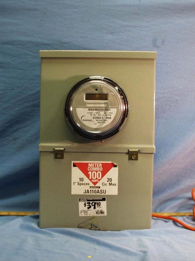
QI2-EMSM-101
Jun 26, 2003vCon RF Meter
Equipment Class
DSS - Part 15 Spread Spectrum Transmitter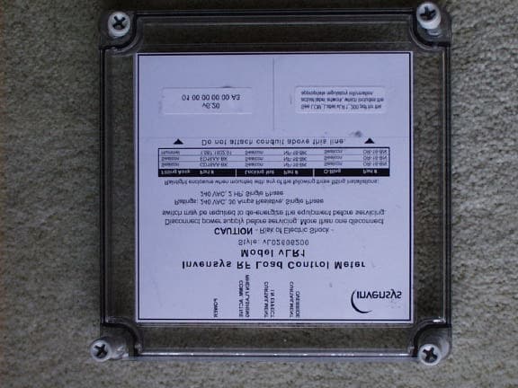
QI2-EMSL-200
Sep 02, 2002Wireless Load Control Meter
Equipment Class
DSS - Part 15 Spread Spectrum Transmitter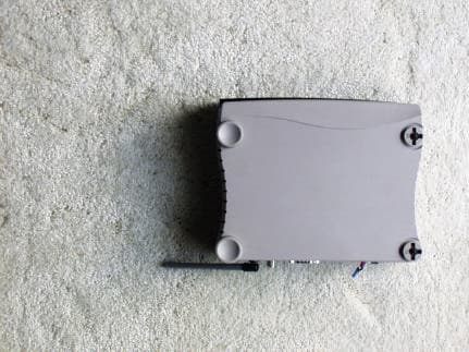
QI2-EMSG-100-CR
Aug 07, 2002Wireless Cable Ready Gateway
Equipment Class
DSS - Part 15 Spread Spectrum Transmitter
QI2-EMSM-100
Aug 01, 2002vCon RF Meter
Equipment Class
DSS - Part 15 Spread Spectrum Transmitter
QI2-EMST-100
Jul 31, 2002RF Thermostat
Equipment Class
DSS - Part 15 Spread Spectrum Transmitter