QI2-EMSL-200Wireless Load Control Meter
Robertshaw Controls Company d/b/a Invensys Home Control Systems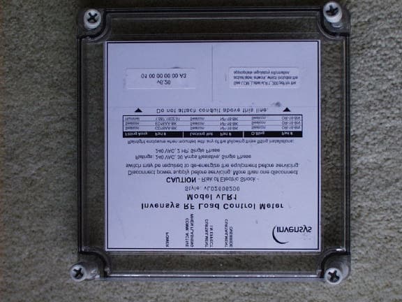
Click to zoom
Application Details
- Equipment Class
- DSS - Part 15 Spread Spectrum Transmitter
- Date of Grant
- Sep 02, 2002
- Application Purpose
- Original Equipment
- Date of Application
- Sep 02, 2002
- Equipment Note
- Wireless Load Control Meter
- Frequency Range
- 905.00000000 - 924.60000000
- Country
- United States
Documents & Files
Document Text
Text extracted from the exhibit documents filed with the FCC. Open a document above to read the original.
Users Manual
TD2001COPYRIGHT © 2002 INVENYS HOME CONTROL SYSTEMS8/6/02 vLR1 Invensys RF Load Control Meter General Instructions Description The Invensys RF Load Control Meter (LCM) is a remote switching device that receives load control OFF and ON commands from the GoodWatts system. Commands are received via an RF Communications network. The LCM is connected in line with the existing electrical wiring to the appliance, which enables it to be mounted at any location with easy access to the existing wiring. The enclosure is watertight, dust tight, and corrosion resistant, making it suitable for both indoor and outdoor locations. Mounting holes are provided at each corner to secure the LCM to a flat surface. TABLE 1. Specifications TABLE 2. Style Chart FIGURE 1.Invensys RF Load Control Meter Note:This equipment has been tested and found to comply with the limits for a Class B digital device, pursuant to Part 15 of the FCC Rules. These limits are designed to provide reasonable protection against harmful interference in a residential installation. This equipment generates, uses and can radiate radio frequency energy and, if not installed and used in accordance with the instructions, may cause harmful interference to radio communications. However, there is no guarantee that interference will not occur in a particular installation. If this equipment does cause harmful interference to radio or television reception, which can be determined by turning the equipment off and on, the user is encouraged to try to correct the interference by one or more of the following measures: – Reorient or relocate the receiving antenna. – Increase the separation between the equipment and receiver. – Connect the equipment into an outlet on a circuit different from that to which the receiver is connected. – Consult the dealer or an experienced radio/TV technician for help. ItemDescription Electrical input: vL02606100: 120 VAC rms, 60 Hz., 2-wire vL02606200: 240 VAC rms, 60 Hz., 2-wire Contact rating: 30A @240VAC rms Wiring Terminals: #14 - #10 AWG, copper conductors only, solid or stranded Operating temperature: -40 to +65 deg. Celsius Storage temperature: -40 to +85 deg. Celsius Humidity tolerance: 0 to 100% RH (non-condensing) Enclosure:NEMA 4x rated Physical dimensions: 7.0” x 7.0” x 3.02” Weight:2 lbs Model StyleDescription vL02606100 – Controls 120 VAC single-phase loads with current up to 30A resistive. – Supports 1 h.p. single phase inductive motor. vL02606200 – Controls 240 VAC single-phase loads with current up to 30A resistive. – Supports 2 h.p. single phase inductive motor. POWER COMM. ACTIVE WHEN FLASHING CURTAILMENT INEFFECT CURTAILMENT OVERRI DE Inve nsys RF Loa d Contr o lMe t e r M odel E M S L - 20 0 C AUTI O N -Ri s k of Ele c tr i cS ho c k - Di s c o nn e c t p ow er s up p ly befo re servi c i n g. More t ha n one disc o n nec t sw it ch ma y b e re q ui r ed to d e-ene r gize th ee q u i p m e nt be for e s e rvic i ng. R a t i n g s : 2 4 0V AC, 30 A mp sR e sist ive, S i n g le P hase 2 4 0 VA C, 2HP, Sin g le P ha s e Do no t a ttac h conduit a bov et his li ne. FCC I D :QI 2 - E MSL-100 This d e v ic e c o mplie s w ith P a r t15 of t he FCC R u l es. O per a t io n i s su bj e ct t o t he fol l ow i n g t wo c ondi t ions : (1 )t hi s dev i ce ma y not c a use ha r mful in t er ference, a nd ( 2) t hi s de v i ce m ust accept an y int erfe r e nc e r e c ei ve d, in c l ud i ng i n ter fe r e nce t h at may caus e un d esir ed ope r ation . R ai nt i g ht e nc l o s u re whe n m oun ted wi t h ei th e rofth e f oll o win gtw o f i t t i n g i nst al l at ions: De s cr i pt ion P ar tNum b e r Fit t in gAssy. CD1 6 A A- B K Lo ckin gNut N P -16-B K O - rin g O R -1 6 - B N De s cri p tion Pa r tNu mber Fitti n gA ss y . E D 1 6 A A - B K Lo c k ing N ut 1 6 -B K O - r i n g6 B N abc INVENSYS RF LOAD CONTROL METER 2PRELIMINARY DOCUMENTTD2001 Installation Caution:This equipment is authorized for use under the United States Federal Communication Commission Rules and Regulations, Code of Federal Regulations Chapter 47 part 15 and must be installed in accordance with the instructions provided in this document. In accordance with FCC requirements, changes or modifications to this equipment that are not expressly approved by the party responsible for FCC compliance could void the user's authority to operate this equipment. Inspection Inspect the carton for damage. If damaged, notify carrier immediately. Inspect LCM for damage. Return damaged products. Requirements – Installer must be a qualified, experienced technician. – Job wiring diagrams –Tools •Drill bits for panel mounting holes •Static protection wrist strap –Mounting screws (4) General Precautions Warning:Electrical shock hazard! High voltage is present in the Load Control Meter. Turn OFF electrical power to the LCM and the electrical appliance prior to installation or service. Failure to turn off power may result in serious personal injury. – Follow Static Precautions when installing this equipment. – Use suitable copper conductors. – Make all connections according to electrical wiring diagram, national and local electrical codes. Static Precautions Static charges damage electronic components. The microprocessor and associated circuitry are sensitive to static discharge. Use the following precautions when installing, servicing, or operating the system. – Work in a static free area – Discharge static electricity by touching a known, securely grounded object. Location The LCM is connected in line with the existing electrical wiring to the appliance, which enables it to be mounted at any location with easy access to the existing wiring. The enclosure is watertight, dust tight, and corrosion resistant, making it suitable for both indoor and outdoor locations. – Avoid mounting locations where excessive moisture, corrosive fumes, vibration, or explosive vapors are present. – Avoid electrical noise interference. Do not install near large contactors, electric…
Text truncated - open the document above for the full version.
Cover Letter(s)
tel: 650-726-1263 fax: 650-726-1252 [email protected] Thomas N. Cokenias EMC &Radio Approvals Test & Consulting Services for Commercial, Military, International Compliance P.O. Box 1086 El Granada, CA 94018 FCC Laboratory31 August 2002 7435 Oakland Mills Road Columbia, MD 21046 Attention: Application Examiner Reviewing Engineer Applicant: Invensys Home Control Systems FCC ID: QI2-EMSL-200 RF Link Load Control Module (LCM) To whom it may concern, Request is hereby submitted, on behalf of my client Invensy HCS to withhold from public review certain portions of the application for equipment certification for the referenced FCC identifier. In particular, the following sections of the application and report are requested to be kept confidential: Block Diagrams Schematic Portion of Operational Description Rationale for request for confidentiality: Invensys has invested considerable time and materials in research and development to produce the referenced product. Disclosure of the confidential portions of this application to competitors would give them competitive advantage in developing similar products. If you have questions or need further information, please contact the undersigned. Sincerely, tel: 650-726-1263 fax: 650-726-1252 [email protected] THOMAS N. COKENIAS EMC Consultant/Agent for Robershaw Control Systems (dba Invensys Home Control systems)
External Photos
Invensys Metering System Load Control Module Product Photographs FCC ID: QI2-EMSL-200 120 VAC cover Invensys Metering System Load Control Module Product Photographs FCC ID: QI2-EMSL-200 240 VAC cover
ID Label/Location Info
L2/N L1 EARTH L2/N L1 L2/N L1 EARTH EARTH L2/N L1 EARTH LOAD CONTROL METER CIRCUIT BREAKER 120 VOLTS 120 VAC Hot Water Heater LOAD CONTROL METER CIRCUIT BREAKER 120 VOLTS 120 VAC Pool Pump 1 HP max EXISTING CIRCUIT DISCONNECT CAUTION: Bonding between conduit connections is not automatic and must be provided as a part of the installation. For supply connections, use No. 14 to 10 AWG wires rated at least 90 o C (194 o F) Use copper conductors only. Torque to 16 in-lbs. Install all wiring in accordance with National and Local codes. Typical Wiring Invensys RF Load Control Meter Model vLR1 CAUTION - Risk of Electric Shock - Disconnect power supply before servicing. Ratings: 120 VAC, 30 Amps Resistive, Single Phase 120 VAC, 1 HP, Single Phase Do not attach conduit above this line. Raintight enclosure when mounted with any of the following three fitting installations: Style: vL02606100 POWER COMM. ACTIVE WHEN FLASHING CURTAILMENT I N EFFECT CURTAILMENT OVERRIDE Fitting Assy. Part # Sealcon CD16AA-BK Sealcon ED16AA-BK Hummel 1.587.1602.01 Locking Nut Part # Sealcon NP-16-BK Sealcon NP-16-BK Sealcon NP-16-BK O-Ring Part # Sealcon OR-16-BN Sealcon OR-16-BN Sealcon OR-16-BN This device complies with Part 15 of the FCC rules. Operation is subject to the following two conditions: (1) this device may not cause harmful interference, and (2) this device must accept any inter- ference received, including interference that may cause undesired operation. LISTED CLOSED ENERGY MANAGEMENT EQUIPMENT 42EB FCC ID: QI2-EMSL-200 L2/N L1 L2/N L1 EARTH EARTH LOAD CONTROL METER CIRCUITBREAKER 240 VOLTS 240 VAC Hot Water Heater L1 L1 EARTH EARTH LOAD CONTROL METER CIRCUITBREAKER 240 VOLTS 240 VAC Pool Pump 2 HP max EXISTING CIRCUIT DISCONNECT CAUTION: Bonding between conduit connections is not automatic and must be provided as a part of the installation. For supply connections, use No. 14 to 10 AWG wires rated at least 90 o C (194 o F) Use copper conductors only. Torque to 16 in-lbs. Install all wiring in accordance with National and Local codes. Typical Wiring L2/NL2/N PO WER COMM. A CTIVE WHEN FLASHING CUR TAILMENT I N EFFECT CUR TAILMENT OVERRIDE CAUTION - Risk of Electric Shock - Disconnect power supply before servicing. More than one disconnect switch may be required to de-energize the equipment before servicing. Ratings: 240 VAC, 30 Amps Resistive, Single Phase 240 VAC, 2 HP, Single Phase Do not attach conduit above this line. Raintight enclosure when mounted with any of the following three fitting installations: In vensys RF Load Control Meter Model vLR1 Style: vL02606200 Fitting Assy. Par t # Sealcon CD16AA-BK Sealcon ED16AA-BK Hummel 1.587.1602.01 Locking Nut Par t # Sealcon NP-16-BK Sealcon NP-16-BK Sealcon NP-16-BK O-Ring Par t # Sealcon OR-16-BN Sealcon OR-16-BN Sealcon OR-16-BN FCC ID: QI2-EMSL-200 This device complies with Par t 15 of the FCC rules. Operation is subject to the following two conditions: (1) this device may not cause harmful interference, and (2) this device must accept any inter- ference received, including interference that may cause undesired operation. LISTED CLOSED ENERGY MANAGEMENT EQUIPMENT 42EB
Internal Photos
Invensys Metering System Load Control Module Product Photographs FCC ID: QI2-EMSL-200 Cover off Invensys Metering System Load Control Module Product Photographs FCC ID: QI2-EMSL-200 LCM and Radio Board Invensys Metering System Load Control Module Product Photographs FCC ID: QI2-EMSL-200 Radio board removed Invensys Metering System Load Control Module Product Photographs FCC ID: QI2-EMSL-200 LCM board wired for 120 VAC Invensys Metering System Load Control Module Product Photographs FCC ID: QI2-EMSL-200 LCM board wired for 240 VAC Invensys Metering System Load Control Module Product Photographs FCC ID: QI2-EMSL-200 Detail, LCM components under RF board Invensys Metering System Load Control Module Product Photographs FCC ID: QI2-EMSL-200 Bottom LCM board Invensys Metering System Load Control Module Product Photographs FCC ID: QI2-EMSL-200 Component side radio board Invensys Metering System Load Control Module Product Photographs FCC ID: QI2-EMSL-200 Foil side radio board antenna
Operational Description
Invensys Home Controls – Home Manager Residential Load Management Service Offering Background Traditionally, utilities have done an excellent job of providing a reliable source of power to their customers. Utilities do this by accurately predicting consumer demand and then ensuring that they have adequate generation resources available to meet that demand. Historically, demand for power increases each year during peak heating and cooling months, resulting in a need for ever increasing amounts of generation capacity. A review of the peak period demand clearly show that we could eliminate the need for a substantial amount of new generation assets if there was a way to shift some of the demand from peak to off peak times. Current Programs Utilities do currently offer demand reduction programs to their customers. These programs are designed to shift loads out of peak periods by providing a financial incentive for consumers to move loads to a time when it is less expensive for the utility to produce or obtain power. Time of day rate is an example of such a program. Another type of program offered by utilities is the traditional Demand Side Management (DSM) program. This type of program provides the customer a monthly credit for allowing the utility to interrupt power to major loads in their home during peaks or emergencies. While both of these programs have been shown to work, they each have their problems. Time of day rate programs are difficult for customers to understand. Therefore these programs have a very low participation rate among the customer base. DSM programs, on the other hand, have a much higher participation rate. However, DSM load sheds are seldom exercised by the utility. And, when the utility does exercise a load shed, the resulting interruption of power tends to affect customer comfort, thereby causing large numbers of customers to drop out of the program. In addition, current DSM programs cannot differentiate between those consumers that contribute to a load control, and those that don’t, while providing incentive credits to all who sign up. While both time of day rates and DSM programs can be effective, each have challenges in the area of customer satisfaction that erode their usefulness. In addition, utilities earn little revenue from these types of offerings and therefore look to new generation as a more economically viable option. GoodWatts To solve this dilemma, Invensys Home Control Systems has developed the Home Manager coupled with the GoodWatts Service offering. The Home Manager is an “always on” home control system that monitors and manages major residential loads. It is designed to reduce the peak demands of the home while maintaining acceptable customer comfort levels. The Home Manager is the next generation of residential load management. How does it work? In each home, the Home Manager operates over a wireless network with a residential gateway communicating with the major loads in the home. The gateway is attached to a broadband network that connects each home to the distribution utility or energy service provider serving the home. This network creates a direct link between the energy supplier and all the major loads in the home. Unlike traditional systems, the in-home network supports a wide array of monitoring and control points including: ! Whole house interval metering ! HVAC thermostat monitoring and control ! Sub-metering and control of other major loads (such as pumps and electric water heaters) ! Net metering for effective management of distributed generation assets Today, the system is designed to provide monitoring and control of these major loads with the potential to expand to other points of control in the future, thus expanding its sphere of control and home automation capabilities. Future features like home security and appliance monitoring are all part of the product road map for the Home Manager system. System Features The unique design of the Home Manager system give it operational characteristics unlike any other system on the market today. Customer Comfort Preserved The Home Manager ensures optimal customer comfort by providing soft load control of HVAC systems. This precise control allows the heating and cooling systems to operate more efficiently without impacting customer comfort levels. This level of control is enabled by the unique temperature ramping capabilities of the Variable Deadband Thermostat. This thermostat manages the environmental comfort range in the home by varying the set point over a range of settings in tenths of a degree. Because of this precise control the system is able to deliver energy reductions using a soft load control eliminating the thermal gain or loss characteristics of traditional control systems which result in customer complaints. Revenue Neutral GoodWatts controls other major loads in such a way that the energy provider does not lose revenue, and the customer’s needs are also met. For instance, while the customer may specifically program a major load, such as a pool pump to run a set number of hours, he is generally indifferent to the exact time that the pump runs. In GoodWatts, items like pool pumps are reprogrammed to run for the same number of hours desired by the consumer, however, the load will not operate during peak periods. The net result is that the energy provider does not have a loss of energy sales, and the consumer does not have a loss of functionality. Therefore, GoodWatts allows utilities to shift loads without the loss of total energy consumed and its associated revenue. Enhanced load profile data allows for equitable distribution of incentive payments to consumer. Another unique feature of the Home Manager is its ability to provide ANSI C12 revenue grade sub metering at the load control level. Home Manager provides individual load profiling as well as a means to verify the exact load reduction contributed by each load to a specific curtailment command. Through this featur…
Text truncated - open the document above for the full version.
RF Exposure Info
RF Exposure (MPE) Calculations 905 - 924.6 MHz Frequency Hopping Spread Spectrum Radio Applicant: Robertshaw Controls Company FCC ID: QI2-EMSL-200 RF Hazard Distance Calculation (worst case) mW/cm2 from Table1:0.60 Max RF Power TX AntennaMPE P, dBmG, dBiSafe Distance, cm 10.562.841.3 Basis of Calculations: E^2/3770 = S, mW/cm2 E, V/m = (Pwatts*Ggain*30)^.5/d, meters d = ((Pwatts*G*30)/3770*S))^0.5Pwatts*Ggain = 10^(PdBm-30+GdBi)/10) NOTE: For mobile or fixed location transmitters, minimum separation distance is 20 cm, even if calculations indicate MPE distance is less
Test Report
FCC ID: QI2-EMSL-200 Invensys Load Control Module (LCM) 1 of 20 900MHz FHSS EMISSIONS TEST REPORT FOR A LOW POWER TRANSMITTER I. GENERAL INFORMATION Requirement: Federal Communications Commissions Test Requirements: 15.205, 15.207, 15.209, 15.247 Applicant: Robertshaw Controls Company d/b/a Invensys Home Control Systems Product ID: FCC ID: QI2-EMSL-200 II. DESCRIPTION OF EQUIPMENT UNDER TEST (EUT) The Invensys FCC ID: QI2-EMSL-200 is a frequency hopping spread spectrum (FHSS) transceiver. The Invensys RF Load Control Meter (LCM) is a remote switching device that receives load control OFF and ON commands from the GoodWatts system. Commands are received via an RF Communications network. The LCM is available in 120 VAC and 240 VAC versions, identical except for transformer tap selection. The LCM operates in the U.S. ISM band between 902 and 928 MHz. The module incorporates a microcontroller and an r.f. integrated circuit that form a frequency hopping spread spectrum transceiver operating under FCC part 15.247. Transmitter Specification TX Power 12dBm Frequency Deviation (FSK) +/- 20 kHz Frequency of operation 905 – 924.6 MHz Data Rate 19.2 kbps Number of channels 50 Channel Separation 400 kHz Typical 20dB occupied bandwidth 150 kHz III. TEST LOCATION All tests were performed at: FCC ID: QI2-EMSL-200 Invensys Load Control Module (LCM) 2 of 20 900MHz FHSS Compliance Certification Services 561F Monterey Road Morgan Hill, CA 95037 T.N. Cokenias 27 August 2002 EMC Consultant/Agent for Invensys FCC ID: QI2-EMSL-200 Invensys Load Control Module (LCM) 3 of 20 900MHz FHSS 1. Antenna connector requirement The antenna is permanently attached to the product. 15.204 Antenna description The load control module transceiver module uses a printed circuit folded dipole antenna: Antenna description Gain MFR name HCST printed ckt antenna 2.84 dBi max (z axia) Invensys HCS Measured antenna data and radiation patterns are presented in a separate pdf attachment. 15.247(a) Frequency hopping spread spectrum definition Pseudorandom frequency hopping sequence: The transmitter cannot coordinate its hopping sequence with the hopping sequence of other transmitters, or vice versa, for the purpose of avoiding the simultaneous occupancy of individual hopping frequencies by multiple transmitters Each access unit has an individual ID number and there is no link or association between two access units so there is no simultaneous occupancy of individual hopping frequency transmission of two or more access units. Equal hopping frequency use: The EUT utilizes 50 hopping channels. Hopset is 50 channels long, then repeats. On average all channels are used equally. System receiver input bandwidth and receiver hopping capability: Receiver 26 dB bandwidth is 200 kHz, approximately equal to 26 dB bandwidth of TX. Receiver channel hops are synchronized to transmitter operating frequency. FCC ID: QI2-EMSL-200 Invensys Load Control Module (LCM) 4 of 20 900MHz FHSS TEST DATA and TEST PROCEDURES - CCS Laboratory Radiated Emissions Test Requirement: 15.205, 15.247 Out of Band Measurements Test Requirement: 15.247 Measurement Equipment Used: HP 8566 Spectrum Analyzer, 30-1000 MHz GHz HP 8447D Pre-amplifier, .1 - 1300 MHz Schaffner/Chase CBL6112B Bilog Antenna, 30 - 2000 MHz HP 8593EM Spectrum Analyzer, 1 - 9.5 GHz Miteq NSP2600-44 Microwave pre-amplifier, 1-26.5 GHz EMCO 3115 Double Ridged Horn antenna, 1 - 18 GHz Radiated emissions generated by the transmitter portion of the EUT were measured. 1. The EUT was placed on a wooden table resting on a turntable on the open air test site. The search antenna was placed 3m from the EUT. The EUT antenna was mounted vertically as per normal installation. 2. The turntable was slowly rotated to locate the direction of maximum emission at each emission falling in the restricted bands of 15.205. 3. Radiated emissions were investigated for a LOW channel, a MID channel, and HIGH channel. Emissions were investigated to the 10 th harmonic. 4. Once maximum direction was determined, the search antenna was raised and lowered in both vertical and horizontal polarizations. The maximum readings so obtained are recorded in the data listed below. Test Results: Worst case results are presented. Refer to data sheets in separate attachments. Restricted band emissions meet 54 dBuV/m. Other undesired emissions from the transmitter meet the -20 dBc requirement in 15.247(c). 22-26 August 2002Engineer;T.Nguyen Compliance Certification Services, Morgan Hill Open Field SiteSite A Invensys Metering Systmes HCS FCC ID: QI2-EMSL-200 Load Conrol Module Equipment for 1-18 GHzEquipment for 18-26.5 GHzEquipment for 26.5-40 GHz HP8566B AnalyzerHP8566B AnalyzerHP8566B Analyzer MITEQ NSP2600-44 PreampHP11975A Preamp (LO)HP 11975A Amplifier (LO) EMCO 3115 Antenna; S/N:2238ARA MWH-1826B & HP11970KHP 11970A External mixer/antenna Cable:15.0feetCable:3.0Cable: IF Only (321 MHz) Conns:4Conns:4 Spectrum Analyzer Settings AveragePeak RBW 1 Mhz1 MHz VBW 10 Hz1 MHz fDistRead PkRead AvAFCLAmpD CorrPk EAv EPk LimitMargin PkAv LimitMargin AvPolarityNotes GHzcmdBuVdBuVdB/mdBdBdBdBuV/mdBuV/mdBuV/mdBdBuV/mdB 905 MHz108.50 1.810200.041.827.92.9-42.5-3.526.588.5-62.0vertical 2.715200.060.857.830.93.4-42.3-3.549.346.374.0-24.754.0-7.7vertical 3.620200.048.340.832.74.1-42.0-3.539.532.074.0-34.554.0-22.0horizontal 4.525200.048.34134.44.7-41.9-3.542.034.774.0-32.054.0-19.3vertical 5.430200.048.837.536.25.3-41.7-3.545.133.874.0-28.954.0-20.2vertical 6.335200.048.337.836.95.7-41.5-3.545.992.0-46.1horizontal 7.240200.048.534.338.36.1-41.2-3.548.292.0-43.8vertical 8.145200.045.234.239.16.5-40.3-3.547.036.074.0-27.054.0-18.0vertical 9.050200.043.533.739.86.9-39.4-3.547.337.574.0-26.754.0-16.5vertical 915 MHz108.00 1.830200.041.628.02.9-42.5-3.526.588.5-19.5vertical 2.745200.060.959.231.03.4-42.2-3.549.547.874.0-24.554.0-6.2horizontal 3.660200.049.543.232.74.1-42.0-3.540.834.554.0-13.254.0-19.5vertical 4.575200.048.340.734.54.8-41.8-3.542.287.7-45.5horizontal 5.4…
Text truncated - open the document above for the full version.
Test Setup Photos
Invensys Metering Systems Load Control Module Test Set-up Photographs FCC ID: QI2-EMSL-200 AC Line Conducted, 120 VAC version Invensys Metering Systems Load Control Module FCC ID: QI2-EMSL-200 AC Line Conducted, 120 VAC unit Invensys Metering Systems Load Control Module FCC ID: QI2-EMSL-200 AC Line Conducted, 240 VAC unit Invensys Metering Systems Load Control Module FCC ID: QI2-EMSL-200 AC Line Conducted, 240 VAC unit Invensys Metering Systems Load Control Module FCC ID: QI2-EMSL-200 Radiated emissions, 240 VAC unit Invensys Metering Systems Load Control Module FCC ID: QI2-EMSL-200 Radiated emissions, 240 VAC Invensys Metering Systems Load Control Module FCC ID: QI2-EMSL-200 Radiated emissions, 120 VAC unit Invensys Metering Systems Load Control Module FCC ID: QI2-EMSL-200 Radiated emissions, 120 VAC unit Invensys Metering Systems Load Control Module FCC ID: QI2-EMSL-200 Radiated emissions 1-9.246 GHz, 120 VAC unit Invensys Metering Systems Load Control Module FCC ID: QI2-EMSL-200 Radiated emissions 1-9.246 GHz, 120 VAC unit
Contact Information
Applicant
Allen J Jones(Project Manager)
Test Firm
Compliance Certification Services IncSteve Cheng
Technical Specifications
| # | Rule Parts | Frequency Range | Power Output |
|---|---|---|---|
| 1 | 15C | 905 MHz - 924.6 MHz | 11.40 mW |
Other Applications from Robertshaw Controls Company d/b/a Invensys Home Control Systems
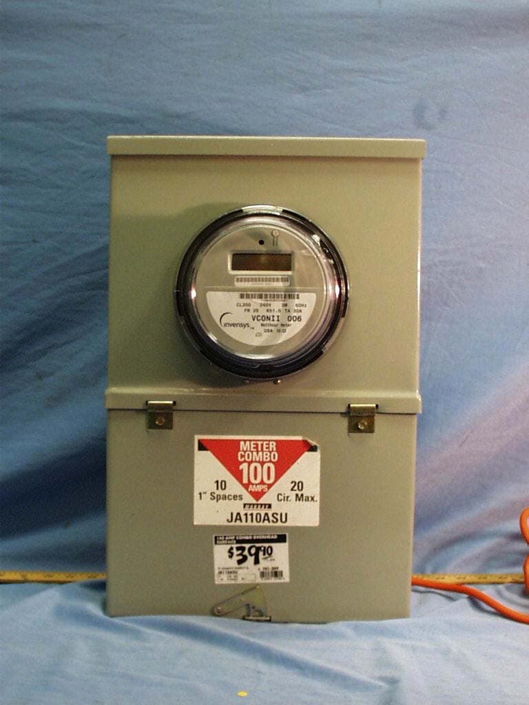
QI2-EMSM-101
Jun 26, 2003vCon RF Meter
Equipment Class
DSS - Part 15 Spread Spectrum Transmitter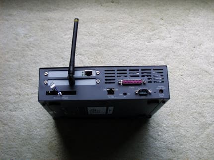
QI2-EMSG
Aug 07, 2002RF Intelliway Gateway
Equipment Class
DSS - Part 15 Spread Spectrum Transmitter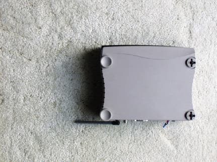
QI2-EMSG-100-CR
Aug 07, 2002Wireless Cable Ready Gateway
Equipment Class
DSS - Part 15 Spread Spectrum Transmitter
QI2-EMSM-100
Aug 01, 2002vCon RF Meter
Equipment Class
DSS - Part 15 Spread Spectrum Transmitter
QI2-EMST-100
Jul 31, 2002RF Thermostat
Equipment Class
DSS - Part 15 Spread Spectrum Transmitter