QI2-EMSM-100vCon RF Meter
Robertshaw Controls Company d/b/a Invensys Home Control Systems
Click to zoom
Application Details
- Equipment Class
- DSS - Part 15 Spread Spectrum Transmitter
- Date of Grant
- Aug 01, 2002
- Application Purpose
- Original Equipment
- Date of Application
- Aug 01, 2002
- Equipment Note
- vCon RF Meter
- Frequency Range
- 905.00000000 - 924.60000000
- Country
- United States
Documents & Files
Document Text
Text extracted from the exhibit documents filed with the FCC. Open a document above to read the original.
Users Manual
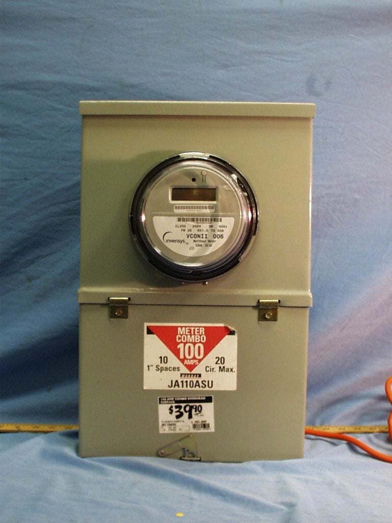
TD2001COPYRIGHT © 2002 INVENYS HOME CONTROL SYSTEMS7/30/02 vSR1 Invensys vCon RF Meter General Instructions Description The vCon™ Single-Phase meter provides Form 2S-240V residential electronic metering with advanced sensor technology and integrated RF network communications capability. The meter displays accumulated electricity usage data on an easy-to-read LCD display, is compatible with industry requirements for mounting and device profile features, and can be dismantled without the use of hand tools. It is available in the industry standard Single- Phase meter Form 2S configuration, and is compliant with all applicable ANSI standards. The vCon meter is a member of the Invensys GoodWatts System family. This meter supports utility, service provider and end-user (home or business-owner) needs for automated utility measurement, data collection, control, notification, and usage management. Warning:Any work on, or near, energized meters, meter sockets, or other metering equipment can present a danger of electrical shock. All work on this product should be performed only by qualif9ed electricians and metering specialists in accordance with local utility safety practices, utility requirements, and procedures outlined in Chapter 14 of The Handbook for Electricity Metering (9th Edition). The information contained in this manual is intended to be an aid to qualified metering personnel. It is not intended to replace the extensive training necessary to handle metering equipment in a safe manner. Use extreme caution when servicing with power on. Precautions All industry safety precautions must be observed during all phases of operation, service, and repair of the Invensys vCon RF Meter meter. Failure to comply with precautions or with specific warnings in this document violates safety standards of design, manufacture, and the intended use of the metering instrument. Invensys assumes no liability for the customer’s failure to comply with these requirements. Caution:This equipment is authorized for use under the United States Federal Communication Commission Rules and Regulations, Code of Federal Regulations Chapter 47 part 15 and must be installed in accordance with the instructions provided in this document. In accordance with FCC requirements, changes or modifications to this equipment that are not expressly approved by the party responsible for FCC compliance could void the user's authority to operate this equipment. FIGURE 1.Invensys vCon RF Meter Note:To comply with FCC RF exposure requirements in section 1.1307, a minimum separation distance of 20 cm (8 inches) is required between the antenna and all persons. Note:This equipment has been tested and found to comply with the limits for a Class B digital device, pursuant to Part 15 of the FCC Rules. These limits are designed to provide reasonable protection against harmful interference in a residential installation. This equipment generates, uses and can radiate radio frequency energy and, if not installed and used in accordance with the instructions, may cause harmful interference to radio communications. However, there is no guarantee that interference will not occur in a particular installation. If this equipment does cause harmful interference to radio or television reception, which can be determined by turning the equipment off and on, the user is encouraged to try to correct the interference by one or more of the following measures: – Reorient or relocate the receiving antenna. – Increase the separation between the equipment and receiver. – Connect the equipment into an outlet on a circuit different from that to which the receiver is connected. – Consult the dealer or an experienced radio/TV technician for help. INVENSYS VCON RF METERGENERAL INSTRUCTIONS 2PRELIMINARY DOCUMENTTD2001 Specifications Residential Electronic Meter Specifications Nominal operating conditions Nameplate VoltageForm 2S: Vn = 240VAC Rated FrequencyFn = 60Hz Power FactorPF = 1.0 Ambient TemperatureTa = 25C +/- 5C Class 200 Test AmpsTA = 30 Amps Environmental specifications Temperature-40× to +85× Celsius (components temperature) Humidity0 to 100% RH (non-condensing) EMI15volts/m, 25MHz to 1000MHz Input specifications Voltage RangeForm 2S: 80% to 115% of Vn (192VAC to 276VAC) Potential Circuit Burden< 5VA, including meter burden at 276VAC Current Range0.1 Amps to 200 Amps Current Circuit Burden< 0.25VA at Test Amps Frequency Range95% to 105% Fn Input over-range requirements Voltage withstand 2.5kV RMS for 60 seconds Current withstandTemporary (0.1 seconds), 7000 Amps peak Continuous (5 hours), 220 Amps RMS Surge withstand Capability (SWC)ANSI C12.1-1995, Sect 10.2.8 Communication RF Network interface900MHz, frequency hopping Operating characteristics BurdenPower Supply: Less than 3 watts Per phase current burden: 0.1 milliohms typical at 25×C Per phase voltage burden: 0.03 watts @ 240 VAC Accuracy (typical)Class 5 Meets ANSI C12.1 accuracy requirements MiscellaneousPer phase starting current: Class 200, 50ma. Minimum recognized outage: 100 ms Absolute maximums VoltageContinuous: 288 VAC Surge Voltages: ANSI C37.90.1: Oscillatory 2.5 kV, 2500 strikes Fast Transient 5 kV, 2500 strikes ANSI C62.41:6 kV @ 1.2/50 us, 10 strikes IEC 801-4” 4 kV, 2.5 kHz repetitive burst for 1 min. Dielectric (ANSI C12.10):2.5 kVrms @ 60Hz, 60 sec. CurrentContinuous: 120% of meter class Temporary (1 sec): 200% of meter class Applicable standards ANSI C12.1 – 1995American National Standard Code for Electricity Metering ANSI C12.10 – 1997American National Standard Code for Watt-hour Meters ANSI C12.20Energy Management Accuracy ANSI C37.90.1Surge Withstand Capability (SWC) IEE C64 GENERAL INSTRUCTIONS 7/30/02PRELIMINARY DOCUMENT3 TD2001INVENSYS VCON RF METERPRINTED IN U.S.A. © Invensys 2002 All specifications are nominal and may change as design improvements are introduced. Invensys shall not be liable for damages resulting from mis- application or misuse of its products. Marks bearing ® and/or …
Text truncated - open the document above for the full version.
Cover Letter(s)
tel: 650-726-1263 fax: 650-726-1252 [email protected] Thomas N. Cokenias EMC &Radio Approvals Test & Consulting Services for Commercial, Military, International Compliance P.O. Box 1086 El Granada, CA 94018 FCC Laboratory31 July 2002 7435 Oakland Mills Road Columbia, MD 21046 Attention: Application Examiner Reviewing Engineer Applicant: Invensys Home Control Systems FCC ID: QI2-EMSM-100 RF Link Electric Meter To whom it may concern, Request is hereby submitted, on behalf of my client Invensy HCS to withhold from public review certain portions of the application for equipment certification for the referenced FCC identifier. In particular, the following sections of the application and report are requested to be kept confidential: Block Diagrams Schematic Operational Description Rationale for request for confidentiality: Invensys has invested considerable time and materials in research and development to produce the referenced product. Disclosure of the confidential portions of this application to competitors would give them competitive advantage in developing similar products. If you have questions or need further information, please contact the undersigned. Sincerely, tel: 650-726-1263 fax: 650-726-1252 [email protected] THOMAS N. COKENIAS EMC Consultant/Agent for Robershaw Control Systems (dba Invensys Home Control systems)
ID Label/Location Info
FCC Label/Location FCC ID: QI2-EMSM-100 This device complies with Part 15 of the FCC Rules. Operation is subject to the following two conditions: (1) This device may not cause harmful interference, and (2) This device must accept any interference received, including interference than may cause undesired operation
RF Exposure Info
FCC ID: QI2-EMSM-100 Invensys HCS Electric Meter 16 of 16 900MHz FHSS RF Exposure (MPE) Calculations 905 - 924.6 MHz Frequency Hopping Spread Spectrum Radio Applicant: Robertshaw Controls Company FCC ID: QI2-EMSM-100 RF Hazard Distance Calculation (worst case) mW/cm2 from Table1:0.60 Max RF PowerTX AntennaMPE P, dBmG, dBiSafe Distance, cm 15.15-1.081.8 Basis of Calculations: E^2/3770 = S, mW/cm2 E, V/m = (Pwatts*Ggain*30)^.5/d, meters d = ((Pwatts*G*30)/3770*S))^0.5Pwatts*Ggain = 10^(PdBm-30+GdBi)/10) NOTE: For mobile or fixed location transmitters, minimum separation distance is 20 cm, even if calculations indicate MPE distance is less
Test Report
FCC ID: QI2-EMSM-100 Invensys HCS Electric Meter 1 of 16 900MHz FHSS EMISSIONS TEST REPORT FOR A LOW POWER TRANSMITTER I. GENERAL INFORMATION Requirement:Federal Communications Commissions Test Requirements: 15.205, 15.207, 15.209, 15.247 Applicant: Robertshaw Controls Company d/b/a Invensys Home Control Systems Product ID: FCC ID: QI2-EMSM-100 II. DESCRIPTION OF EQUIPMENT UNDER TEST (EUT) The Invensys FCC ID: QI2-EMSM-100 a frequency hopping spread spectrum (FHSS) transceiver. The Invensys “vCon RF Meter” unit is a single phase electricity meter that utilizes an iCon Electric Meter transceiver module to communicate accumulated electricity readings to the RF Gateway unit. The Electric Meter Transceiver Module operates in the U.S. ISM band between 902 and 928 MHz. The module incorporates a microcontroller and an r.f. integrated circuit that form a frequency hopping spread spectrum transceiver operating under FCC part 15.247. . Transmitter Specification TX Power12dBm Frequency Deviation (FSK)+/- 20 kHz Frequency of operation905 – 924.6 MHz Data Rate19.2 kbps Number of channels50 Channel Separation400 kHz Typical 20dB occupied bandwidth 150 kHz III. TEST LOCATION All tests were performed at: Compliance Certification Services 561F Monterey Road Morgan Hill, CA 95037 T.N. Cokenias29 July 2002 EMC Consultant/Agent for Invensys FCC ID: QI2-EMSM-100 Invensys HCS Electric Meter 2 of 16 900MHz FHSS 1. Antenna connector requirement The antenna is permanently attached to the product. 15.204 Antenna description The electric meter transceiver module uses a permanently attached built-in antenna: Antenna descriptionGainMFR name electric meter antenna-1.08 dBi maxInvensys HCS Measured antenna data and radiation patterns are presented in a separate pdf attachment. 15.247(a) Frequency hopping spread spectrum definition Pseudorandom frequency hopping sequence: The transmitter cannot coordinate its hopping sequence with the hopping sequence of other transmitters, or vice versa, for the purpose of avoiding the simultaneous occupancy of individual hopping frequencies by multiple transmitters Each access unit has an individual ID number and there is no link or association between two access units so there is no simultaneous occupancy of individual hopping frequency transmission of two or more access units. Equal hopping frequency use: The EUT utilizes 50 hopping channels. Hopset is 50 channels long, then repeats. On average all channels are used equally. System receiver input bandwidth and receiver hopping capability: Receiver 26 dB bandwidth is 200 kHz, approximately equal to 26 dB bandwidth of TX. Receiver channel hops are synchronized to transmitter operating frequency. FCC ID: QI2-EMSM-100 Invensys HCS Electric Meter 3 of 16 900MHz FHSS TEST DATA and TEST PROCEDURES - CCS Laboratory Radiated Emissions Test Requirement: 15.205, 15.247 Out of Band Measurements Test Requirement: 15.247 Measurement Equipment Used: HP 8566 Spectrum Analyzer, 30-1000 MHz GHz HP 8447D Pre-amplifier, .1 - 1300 MHz Schaffner/Chase CBL6112B Bilog Antenna, 30 - 2000 MHz HP 8593EM Spectrum Analyzer, 1 - 9.5 GHz Miteq NSP2600-44 Microwave pre-amplifier, 1-26.5 GHz EMCO 3115 Double Ridged Horn antenna, 1 - 18 GHz Radiated emissions generated by the transmitter portion of the EUT were measured. 1. The EUT was placed on a wooden table resting on a turntable on the open air test site. The search antenna was placed 3m from the EUT. The EUT antenna was mounted vertically as per normal installation. 2. The turntable was slowly rotated to locate the direction of maximum emission at each emission falling in the restricted bands of 15.205. 3. Radiated emissions were investigated for a LOW channel, a MID channel, and HIGH channel. Emissions were investigated to the 10 th harmonic. 4. Once maximum direction was determined, the search antenna was raised and lowered in both vertical and horizontal polarizations. The maximum readings so obtained are recorded in the data listed below. Test Results: Worst case results are presented. Refer to data sheets in separate attachments. Restricted band emissions meet 54 dBuV/m. Other undesired emissions from the transmitter meet the -20 dBc requirement in 15.247(c). 24-26 July 2002Engineer;C. Pang Compliance Certification Services, Morgan Hill Open Field SiteSite A Invensys Metering Systmes HCS FCC ID: QI2-EMSM-100 Electric Meter Equipment for 1-18 GHzEquipment for 18-26.5 GHzEquipment for 26.5-40 GHz HP8566B AnalyzerHP8566B AnalyzerHP8566B Analyzer MITEQ NSP2600-44 PreampHP11975A Preamp (LO)HP 11975A Amplifier (LO) EMCO 3115 Antenna; S/N:2238ARA MWH-1826B & HP11970KHP 11970A External mixer/antenna Cable:15.0feetCable:3.0Cable: IF Only (321 MHz) Conns:4Conns:4 Spectrum Analyzer Settings AveragePeak RBW 1 Mhz1 MHz VBW 10 Hz1 MHz fDistRead PkRead AvAFCLAmpD CorrPk EAv EPk LimitMargin PkAv LimitMargin AvPolarityNotes GHzcmdBuVdBuVdB/mdBdBdBdBuV/mdBuV/mdBuV/mdBdBuV/mdB 905 MHz300.079.520.37.6107.5 1.810300.032.527.92.9-42.50.020.887.5-66.7vertical 2.715300.056.54830.93.4-42.30.048.540.074.0-25.554.0-14.0vertical 3.620300.048.335.1732.74.1-42.00.043.129.974.0-30.954.0-24.1horizontal 4.525300.044.6732.534.44.7-41.90.041.929.774.0-32.154.0-24.3vertical 5.430300.046.534.236.25.3-41.70.046.334.074.0-27.754.0-20.0vertical 6.335300.045.53336.95.7-41.50.046.687.5-40.9vertical 7.240300.046.1733.538.36.1-41.20.049.487.5-38.1vertical 8.145300.045.3333.339.16.5-40.30.050.738.774.0-23.354.0-15.3vertical 9.050300.044.673339.86.9-39.40.052.040.374.0-22.054.0-13.7vertical 915 MHz300.081.020.47.7109.1 1.830300.031.528.02.9-42.50.019.989.1-20.0vertical 2.745300.051.945.731.03.4-42.20.044.137.974.0-29.954.0-16.1horizontal 3.660300.04838.8332.74.1-42.00.042.833.754.0-11.254.0-20.3vertical 4.575300.046.8334.534.54.8-41.80.044.289.1-44.9vertical 5.490300.04634.536.35.3-41.70.045.989.1-43.2vertical 6.405300.045.6733.6737.05.8-41.50.047.089.1-42.1vertical 7.320300.045.8334.238.46.2-41.10.049.337.774.0-24.754.0-16.3vertical 8.235300.045.533…
Text truncated - open the document above for the full version.
Contact Information
Applicant
Allen J Jones(Project Manager)
Test Firm
Compliance Certification Services IncSteve Cheng
Technical Specifications
| # | Rule Parts | Frequency Range | Power Output |
|---|---|---|---|
| 1 | 15C | 905 MHz - 924.6 MHz | 33.00 mW |
Other Applications from Robertshaw Controls Company d/b/a Invensys Home Control Systems
QI2-EMSM-101
Jun 26, 2003vCon RF Meter
Equipment Class
DSS - Part 15 Spread Spectrum Transmitter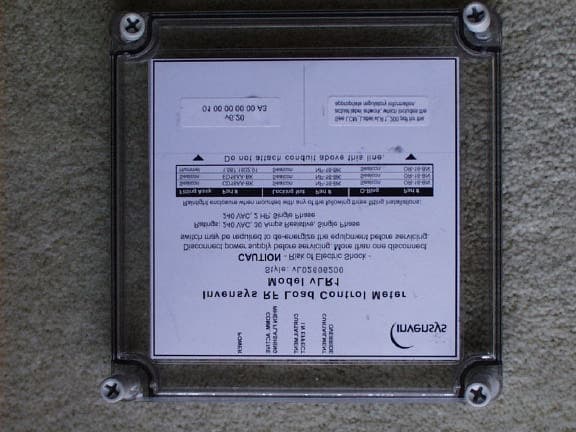
QI2-EMSL-200
Sep 02, 2002Wireless Load Control Meter
Equipment Class
DSS - Part 15 Spread Spectrum Transmitter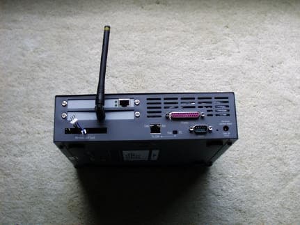
QI2-EMSG
Aug 07, 2002RF Intelliway Gateway
Equipment Class
DSS - Part 15 Spread Spectrum Transmitter
QI2-EMSG-100-CR
Aug 07, 2002Wireless Cable Ready Gateway
Equipment Class
DSS - Part 15 Spread Spectrum Transmitter
QI2-EMST-100
Jul 31, 2002RF Thermostat
Equipment Class
DSS - Part 15 Spread Spectrum Transmitter