QIC-BT0001Bluetooth BLE 4.0 module
PENPOWER TECHNOLOGY LTD.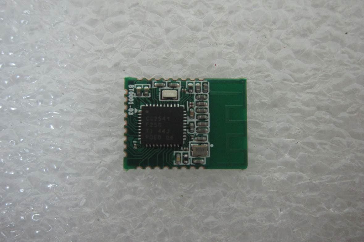
Click to zoom
Application Details
- Equipment Class
- DTS - Digital Transmission System
- Date of Grant
- Oct 29, 2014
- Application Purpose
- Original Equipment
- Date of Application
- Oct 29, 2014
- Equipment Note
- Bluetooth BLE 4.0 module
- Frequency Range
- 2402.00000000 - 2480.00000000
- Company
- PENPOWER TECHNOLOGY LTD.
- Country
- Taiwan
Documents & Files
Document Text
Text extracted from the exhibit documents filed with the FCC. Open a document above to read the original.
Users Manual
Bluetooth 4.0 BLE Module Model: BT0001 Manual PenPower The BT0001 is a high performance Bluetooth 4.0 BLE, (Bluetooth Low Energy) module using TI's CC2541 SOC chip. The module is suitable for smart hand-held device low power accessories. The BT0001 can support ultra-low-power batteries and sensor-based data collection framework. The Bluetooth 4.0 BLE is the technology adapted wide-ranging deployment in various computing & communication application fields. BT0001 build-in 8051 MCU, in-system software stack programmable flash memory, 8-KB RAM, and many multiple configuration options other powerful supporting features and peripherals, including UART, IIC and GPIO. BT0001 is 25-pin I/O interface (with back size 9 pin) to bring UART, I²C or GPIO data to wireless through Bluetooth BLE protocol. BT0001 build-in the hi-efficiency PCB antenna for compact and easy assembly application. The BT0001 is highly suited for systems where allowing llowingllowing llowing ultralow power consumption is required. It is good applications pplicationspplications pplications to run on the system specified by various operating modes. short transition's network application. BT0001 offers absolute interoperability with different vendors’ Bluetooth through the Bluetooth low energy and peripheral Roles proprietary 2.4-GHz applications. It enables robust network nodes to be built with low power consumption To speed up the design process, BT0001 provide user friendly library for both iOS ,Android, PC Windows and MAC developer. The App designer can focus on their application topic, it is not necessary for her/him to distract on wireless communication issue. In addition, we also provide software and hardware develop kit for engineer firmware development and upgrade. Property PropertyProperty Property: Chipset : Main Chip: TI CC2541 CPU: Low-Power 8051 core with Code protect RAM: 8-KB RAM With Retention in All Power Program Flash: In-System-Programmable Flash, 128KB/256KB Watchdog Timer Wireless: Wireless:Wireless: Wireless: Bluetooth low energy technology compatible AES Security Coprocessor AES Security CoprocessorAES Security Coprocessor AES Security Coprocessor 2.4 2.42.4 2.4- -- -GHz GHz GHz GHz Bluetooth Bluetooth Bluetooth Bluetooth low energy Compliant low energy Compliantlow energy Compliant low energy Compliant Excellent Receiver Sensitivity ( Excellent Receiver Sensitivity (Excellent Receiver Sensitivity ( Excellent Receiver Sensitivity (– –– –94 dBm at 1 Mbps ) 94 dBm at 1 Mbps )94 dBm at 1 Mbps ) 94 dBm at 1 Mbps ) Antenna: on board PCB antenna Antenna: on board PCB antennaAntenna: on board PCB antenna Antenna: on board PCB antenna Peripheral PeripheralPeripheral Peripheral: I²C interface 12-Bit ADC With Eight Channels and Configurable Resolution Powerful USARTs Battery Monitor Temperature Sensor Standard Conformance Standard ConformanceStandard Conformance Standard Conformance: Bluetooth v4.0 Compliant Protocol Stack for Single-Mode BLE Solution Frequency Range: Frequency Range: Frequency Range: Frequency Range: 2.412 ~ 2.4835GHz Interface: Interface:Interface: Interface: Wireless: 2.4G Bluetooth BLE I²C: Hardward IIC USARTs GPIO Antenna: Antenna: Antenna: Antenna: PCB Antenna on board -Active Mode RX down to: 17.9mA -Active Mode TX(0dbm): 18.2mA -Power Mode 1(4-us Wake-Up): 270uA -Power Mode 2(Sleep Timer On): 1uA -Power Mode 3(External Interrupts): 0.5uA - Wide Supply-Voltage Range (2 V–3.6 V) Power Supply : Power Supply : Power Supply : Power Supply : 3.3V input PCBA PCBA PCBA PCBA Dimension DimensionDimension Dimension: : : : 15(W) x 18(L) x 2.03 (H) mm. Environment EnvironmentEnvironment Environment- -- -Friendly Compliance: Friendly Compliance: Friendly Compliance: Friendly Compliance: RoHS SW: SW:SW: SW: iOS Library: Supported Android Library: Supported PC Windows Library: Supported MAC OS Library: Supported Federal Communications Commission (FCC) Statement The final end product must be labeled in a visible area with the following: “Contains FCC ID: QIC-BT0001”. The Original Equipment Manufacturer (OEM) must ensure that the OEM modular transmitter must be labeled with its own FCC ID number. This includes a clearly visible label on the outside of the final product enclosure that displays the contents shown below. If the FCC ID is not visible when the equipment is installed inside another device, then the outside of the device into which the equipment is installed must also display a label referring to the enclosed equipment. You are cautioned that changes or modifications not expressly approved by the part responsible for compliance could void the user’s authority to operate the equipment. This equipment has been tested and found to comply with the limits for a Class B digital device, pursuant to part 15 of the FCC rules. These limits are designed to provide reasonable protection against harmful interference in a residential installation. This equipment generates, uses and can radiate radio frequency energy and, if not installed and used in accordance with the instructions, may cause harmful interference to radio communications. However, there is no guarantee that interference will not occur in a particular installation. If this equipment does cause harmful interference to radio or television reception, which can be determined by turning the equipment off and on, the user is encouraged to try to correct the interference by one or more of the following measures: -Reorient or relocate the receiving antenna. -Increase the separation between the equipment and receiver. -Connect the equipment into an outlet on a circuit different from that to which the receiver is connected. -Consult the dealer or an experienced radio/TV technician for help. This device complies with Part 15 of the FCC Rules. Operation is subject to the following two conditions: 1) this device may not cause harmful interference, and 2) this device must accept any interference received, including interference that may cause undesired operation…
Text truncated - open the document above for the full version.
Cover Letter(s)
SCS-F18: Project and Product Certification Representative Authorization Letter Page 1 of 2 Rev 5.0 775 Montague Expressway Milpitas, CA 95035 Tel: 408-526-1188 Fax: 408-526-1088 Email: [email protected] Project and Product Certification Representative Authorization Letter Reason for Amendment (current / obsolete) Revision History Approved Date From To Initial Release (obsolete) 1.0 1.0 Nov-14-2006 Revised wording (obsolete) 1.0 2.0 Sept–25-2007 Updated company template (obsolete) 2.0 3.0 Jan-31-2012 Updated letter information (obsolete) 3.0 4.0 May-23-2014 Added FCC ID field (current) 4.0 5.0 Sept 16 2014 SCS-F18: Project and Product Certification Representative Authorization Letter Page 2 of 2 Rev 5.0 2014/10/1 To: SIEMIC, Inc. 775 Montague Expressway, Milpitas, CA 95035 USA Dear Sir/Madam, Re: Project and Product Certification Representative Authorization Letter We, PENPOWER TECHNOLOGY LTD. hereby authorize SIEMIC, Inc. to act as Certification Body for certifying for the following project(s): Product description: Bluetooth BLE 4.0 module Type designation: BT0001 FCC ID : QIC- BT0001 Sinc erely, Client’s signature Kevin Chang / Senior Manager PENPOWER TECHNOLOGY LTD. Address: 7F, NO. 47, Lane 2, Sec. 2, Kuang-Fu Rd., Hsinchu City, Taiwan
Cover Letter(s)
SCS-F19: Confidentiality Request Letter Page 1 of 2 Rev 3.0 775 Montague Expressway Milpitas, CA 95035 Tel: 408-526-1188 Fax: 408-526-1088 Email: [email protected] Confidentiality Request Letter Reason for Amendment (current / obsolete) Revision History Approved Date From To Initial Release (obsolete) 1.0 1.0 Nov-14-2006 Adding CFR 2.459 (obsolete) 1.0 2.0 August – 11 - 2008 Updated company template & Added text box (current) 2.0 3.0 Jan-31-2012 SCS-F19: Confidentiality Request Letter Page 2 of 2 Rev 3.0 2014/10/1 To: Federal Communications Commission Authorization and Evaluation Division 7435 Oakland Mills Road Columbia, MD Subject: Permanent Confidentiality Request for FCC ID: QIC- BT0001 We h ereby request confidential treatment of information accompanying this application as outlined below: - e.g. Block Diagram - e.g. Schematics - e.g. Operational Description The above materials contain trade secrets and proprietary information not customarily released to the public. The public disclosure of these materials may be harmful to the applicant and provide unjustified benefits to its competitors. The applicant understands that pursuant to Section 0.457 & 0.459 of the Rules, disclosure of this application and all accompanying documentation will not be made before the date of the Grant for this application. Sincerely, Client’s signature : Kevin Chang / Senior Manager PENPOWER TECHNOLOGY LTD. Address: 7F, NO. 47, Lane 2, Sec. 2, Kuang-Fu Rd., Hsinchu City, Taiwan
Cover Letter(s)
SCS-F26 Modular Approval Letter Page 1 of 2 Rev 7.0 775 Montague Expressway Milpitas, CA 95035 Tel: 408-526-1188 Fax: 408-526-1088 Email: [email protected] Modular Approval Declaration Letter Reason for Amendment (current / obsolete) Revision History Approved Date From To Initial Release (Obsolete) 1.0 1.0 Dec-04-2006 Added IC Modular Letter (Obsolete) 1.0 2.0 Feb 16 2009 Add LMA and MA option (Obsolete) 2.0 3.0 April 14 2010 Revised per RSS Gen issue 3.0 (Obsolete) 3.0 4.0 Jan 12 2011 Removed Foot(2) (obsolete) 4.0 5.0 July 19 2011 Adding New note per KDB996369 D01 V01R03 (obsolete) 5.0 6.0 August 29 2011 Updated company template & Added text box (current) 6.0 7.0 Jan-31-2012 SCS-F26 Modular Approval Letter Page 2 of 2 Rev 7.0 (Date) 1/10/14 (Product name) FCC ID : QIC-BT0001 , is seeking FCC Authorization as a Single Modular transmitter / Single Limited Modular Approval (Please check one). The EUT meets the requirements for Single Modular approval / Single Limited Modular Approval (please check one) as detailed in FCC public Notice DA00-1407. Compliance to each of the requirements is described below : Questions are: * Please provide a detailed explanation if the answer is “No.” 1. “The modular transmitter must have its own RF shielding.” Yes / No 2. “The modular transmitter must have buffered modulation/data inputs.” Yes / No 3. “The modular transmitter must have its own power supply regulation.” Yes / No 4. “The modular transmitter must comply with the antenna requirements of section 15.203 and 15.204(c).” Yes / No 5. “The modular transmitter must be tested in a stand-alone configuration.” Yes / No 6. “The modular transmitter must be labeled with its own FCC ID number.” Yes / No 7. “The modular transmitter must comply with any specific rule or operating requirements applicable to the transmitter and the manufacture must provide adequate instruction along with the module to explain any such requirements.” Yes / No 8. “The modular transmitter must comply with any applicable RF exposure requirements.” Yes / No Note: (1) LMA may be granted when one or more of the requirements in the table above cannot be demonstrated. LMA will also be issued in those instances where applicants can demonstrate that they will retain control over the final installation of the device, such that compliance of the end product is assured. In such cases, an operating condition on the LMA for the module must state that the module is only approved for use when installed in devices produced by a specific manufacturer. When LMA is sought, the application for equipment certification must specifically state how control of the end product into which the module will be installed, and will be maintained, such that full compliance of the end product is always ensured. (2) Please provide Clear and specific instructions describing the conditions, limitations and procedures for third-parties to use and/or integrate the module into a host device. (3) For non-Software Defined Radio transmitter modules where software is used to ensure compliance of the device, technical description of how such control is implemented to ensure prevention of third party modification must be provided (see KDB 594280). Note 1: Compliance of a module in its final configuration is the responsibility of the applicant. A host device will not be considered certified if the instructions regarding antenna configuration provided in the original description, of one or more separately certified modules it contains, were not followed. Example: A separately certified low-power transceiver module using Bluetooth technology which is housed in a desktop computer, laptop or peripheral does not require the overall system to be recertified, if the desktop computer, laptop or peripheral, as a stand-alone unit, complies with all applicable technical standards. Client’s signature Kevin Chang / Senior Manager PENPOWER TECHNOLOGY LTD. Address: 7F, NO. 47, Lane 2, Sec. 2, Kuang-Fu Rd., Hsinchu City, Taiwan
External Photos
FCC ID: QIC-BT0001 International Standards Laboratory Report Number: ISL-14LR139FC-MA PHOTOGRAPHS OF EUT FCC ID: QIC-BT0001 International Standards Laboratory Report Number: ISL-14LR139FC-MA EUT 1 EUT 2 BT Antenna
ID Label/Location Info
FCC ID LABEL FORMAT AND LOCATION Applicant: PENPOWER TECHNOLOGY LTD. FCC ID: QIC-BT0001 FCC ID: QIC-BT0001
Internal Photos
FCC ID: QIC-BT0001 International Standards Laboratory Report Number: ISL-14LR139FC-MA PHOTOGRAPHS OF EUT FCC ID: QIC-BT0001 International Standards Laboratory Report Number: ISL-14LR139FC-MA EUT 1 EUT 2 BT Antenna
RF Exposure Info
FCC ID: QIC-BT0001 International Standards Laboratory 1 RF EXPOSURE 1.1 Standard Applicable According to§2.1093 this is a Portable device. For The radiation source included into the device the output power is taken from a corresponding RF test report. If needed the output power is converted to source based, time – average out power. Finally the output power is compared to FCC and IC low power SAR evaluation exemption level. FCC SAR test exclusion: According to KDB 447498 D01 General RF Exposure Guidance v05r02, Appendix A requirement, “The equation and threshold in section 4.3.1 must be applied to determine SAR test exclusion.” 4.3.1. Standalone SAR test exclusion considerations Unless specifically required by the published RF exposure KDB procedures, standalone 1-g head or body and 10-g extremity SAR evaluation for general population exposure conditions, by measurement or numerical simulation, is not required when the corresponding SAR Test Exclusion Threshold condition, listed below, is satisfied. These test exclusion conditions are based on source-based time-averaged maximum conducted output power of the RF channel requiring evaluation, adjusted for tune-up tolerance, and the minimum test separation distance required for the exposure conditions.23 The minimum test separation distance is determined by the smallest distance from the antenna and radiating structures or outer surface of the device, according to the host form factor, exposure conditions and platform requirements, to any part of the body or extremity of a user or bystander (see 5) of section 4.1). To qualify for SAR test exclusion, the test separation distances applied must be fully explained and justified by the operating configurations and exposure conditions of the transmitter and applicable host platform requirements, typically in the SAR measurement or SAR analysis report, according to the required published RF exposure KDB procedures. When no other RF exposure testing or reporting is required, a statement of justification and compliance must be included in the equipment approval, in lieu of the SAR report, to qualify for the SAR test exclusion. When required, the device specific conditions described in the other published RF exposure KDB procedures must be satisfied before applying these SAR test exclusion provisions; for example, handheld PTT two-way radios, handsets, laptops & tablets etc.24 1) The 1-g and 10-g SAR test exclusion thresholds for 100 MHz to 6 GHz at test separation distances ≤ 50 mm are determined by: FCC ID: QIC-BT0001 International Standards Laboratory [(max. power of channel, including tune-up tolerance, mW)/(min. test separation distance, mm)] · [√f(GHz)] ≤ 3.0 for 1-g SAR and ≤ 7.5 for 10-g extremity SAR,25 where • f(GHz) is the RF channel transmit frequency in GHz • Power and distance are rounded to the nearest mW and mm before calculation26 • The result is rounded to one decimal place for comparison • 3.0 and 7.5 are referred to as the numeric thresholds in the step 2 below The test exclusions are applicable only when the minimum test separation distance is ≤ 50 mm and for transmission frequencies between 100 MHz and 6 GHz. When the minimum test separation distance is < 5 mm, a distance of 5 mm according to 5) in section 4.1 is applied to determine SAR test exclusion. IC Exemption from Routine Evaluation Limits – SAR Evaluation: RSS 102 Issue 4 SAR evaluation is required if the separation distance between the user and the radiating element of the device is less than or equal to 20 cm, except when the device operates as follows: above 2.2 GHz and up to 3 GHz inclusively, and with output power (i.e. the higher of the conducted or radiated (e.i.r.p.) source-based, time-averaged output power) that is less than or equal to 20 mW for general public use and 100 mW for controlled use; 1.2 Measurement Result: FCC: Frequency (MHz) Max power (dBm) Antenna Gain(dBi) EIRP Power (dBm) tune- up tolerance( dB) Max power (mW) Min Distance (mm) Result Limit (3.0 @ 1g SAR) 2402-1.035.304.2724.2364305.001.3133.0 2440-1.955.303.3523.4276785.001.0713.0 2480-2.695.302.6122.8906805.000.9103.0 Max Power(mW) =10^((Max Power(dBm) + Tune-up tolerance(dB) )/10) Result = Max Power (mW) / min. distance(mm) * √f(GHz) IC: The Measured Max. conducted output power is -1.03dBm (0.789 mW), e.i.r.p.output power is 4.27dBm (2.673 mW), which is lower than the threshold power level 20mW in RSS 102 issue 4. The SAR measurement is not necessary.
Test Report
Page: 1 of 41 TEST REPORT of FCC Part 15 Subpart C New Application; Class I PC; Class II PC Limited Module Product : Bluetooth BLE 4.0 module Brand: PenPower Model: BT0001 Model Difference: N/A FCC ID: QIC-BT0001 FCC Rule Part: §15.247, Cat: DTS Applicant: PENPOWER TECHNOLOGY LTD. Address: 7F, NO. 47, Lane 2, Sec. 2, Kuang-Fu Rd., Hsinchu City, Taiwan Test Performed by: International Standards Laboratory <Lung-Tan LAB> *Site Registration No. BSMI: SL2-IN-E-0013; MRA TW1036; TAF: 0997; IC: IC4067B-3; *Address: No. 120, Lane 180, San Ho Tsuen, Hsin Ho Rd. Lung-Tan Hsiang, Tao Yuan County 325, Taiwan *Tel : 886-3-407-1718; Fax: 886-3-407-1738 Report No.: ISL-14LR139FC-MA Issue Date : 2014/10/29 Test results given in this report apply only to the specific sample(s) tested and are traceable to nation- al or international standard through calibration of the equipment and evaluating measurement uncertainty herein. This report MUST not be used to claim product en- dorsement by TAF, NVLAP or any agency of the Government. This test report shall not be reproduced except in full, without the written approval of International Standards Laboratory. -2 of 41- FCC ID: QIC-BT0001 International Standards Laboratory Report Number: ISL-14LR139FC-MA VERIFICATION OF COMPLIANCE Applicant: PENPOWER TECHNOLOGY LTD. Product Description: Bluetooth BLE 4.0 module Brand Name: PenPower Model No.: BT0001 Model Difference: N/A FCC ID: QIC-BT0001 Date of test: 2014/05/29 ~ 2014/10/22 Date of EUT Received: 2014/05/29 We hereby certify that: All the tests in this report have been performed and recorded in accordance with the standards de- scribed above and performed by an independent electromagnetic compatibility consultant, Interna- tional Standards Laboratory. The test results contained in this report accurately represent the measurements of the characteristics and the energy generated by sample equipment under test at the time of the test. The sample equip- ment tested as described in this report is in compliance with the limits of above standards. Test By: Date: 2014/10/29 Dion Chang / Engineer Prepared By: Date: 2014/10/29 Eva Kao / Asst. Supervisor Approved By: Date: 2014/10/29 Vincent Su / Technical Manager -3 of 41- FCC ID: QIC-BT0001 International Standards Laboratory Report Number: ISL-14LR139FC-MA Version Version No. Date Description 00 2014/10/29 Initial creation of document -4 of 41- FCC ID: QIC-BT0001 International Standards Laboratory Report Number: ISL-14LR139FC-MA Table of Contents 1 GENERAL INFORMATION .................................................................................................... 6 1.1 Related Submittal(s) / Grant (s) ..................................................................................................... 7 1.2 Test Methodology .......................................................................................................................... 7 1.3 Test Facility .................................................................................................................................... 7 1.4 Special Accessories ........................................................................................................................ 7 1.5 Equipment Modifications ............................................................................................................... 7 2 SYSTEM TEST CONFIGURATION ....................................................................................... 8 2.1 EUT Configuration ........................................................................................................................ 8 2.2 EUT Exercise ................................................................................................................................. 8 2.3 Test Procedure ................................................................................................................................ 8 2.4 Configuration of Tested System ..................................................................................................... 9 3 SUMMARY OF TEST RESULTS .......................................................................................... 10 4 DESCRIPTION OF TEST MODES ....................................................................................... 10 5 CONDUCTED EMISSION TEST........................................................................................... 11 5.1 Standard Applicable: .................................................................................................................... 11 5.2 Measurement Equipment Used: ................................................................................................... 11 5.3 EUT Setup: ................................................................................................................................... 11 5.4 Measurement Procedure: ............................................................................................................. 12 5.5 Measurement Result: ................................................................................................................... 12 6 PEAK /AVERAGE OUTPUT POWER MEASUREMENT................................................. 15 6.1 Standard Applicable: .................................................................................................................... 15 6.2 Measurement Equipment Used: ................................................................................................... 16 6.3 Test Set-up: .................................................................................................................................. 16 6.4 Measurement Procedure: ............................................................................................................. 16 6.5 Measurement Result: ................................................................................................................... 16 7 6dB Bandwidth(EBW) ....................................…
Text truncated - open the document above for the full version.
Test Setup Photos
FCC ID: QIC-BT0001 International Standards Laboratory Report Number: ISL-14LR139FC-MA PHOTOGRAPHS OF SET UP FCC ID: QIC-BT0001 International Standards Laboratory Report Number: ISL-14LR139FC-MA Radiated Emission Set up Photo FCC ID: QIC-BT0001 International Standards Laboratory Report Number: ISL-14LR139FC-MA FCC ID: QIC-BT0001 International Standards Laboratory Report Number: ISL-14LR139FC-MA FCC ID: QIC-BT0001 International Standards Laboratory Report Number: ISL-14LR139FC-MA Conducted Emission Set up Photo FCC ID: QIC-BT0001 International Standards Laboratory Report Number: ISL-14LR139FC-MA
Contact Information
Applicant
Kevin Chang(Senior Manager)
Test Firm
International Standards Laboratory Corp.Benson Chen
Technical Specifications
| # | Rule Parts | Frequency Range | Power Output |
|---|---|---|---|
| 1 | 15C | 2.40 GHz - 2.48 GHz | 800.00 µW |
Other Applications from PENPOWER TECHNOLOGY LTD.

QIC-MSE10
Dec 28, 2022WorldPenScan Wifi
Equipment Class
DSS - Part 15 Spread Spectrum Transmitter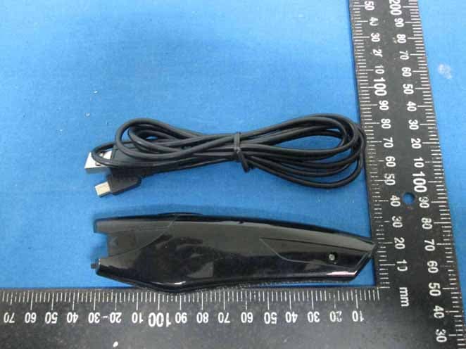
QIC-MSE04
Dec 29, 2013WorldPenScan BT
Equipment Class
DSS - Part 15 Spread Spectrum Transmitter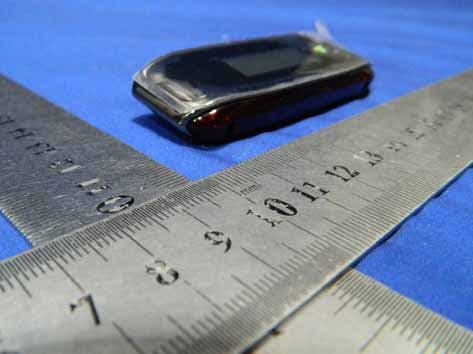
QIC-INK01A
Mar 25, 2013MyInk
Equipment Class
DSS - Part 15 Spread Spectrum Transmitter