QIIRY1012WCAMedical Image Processing Unit
Rayence Co., Ltd.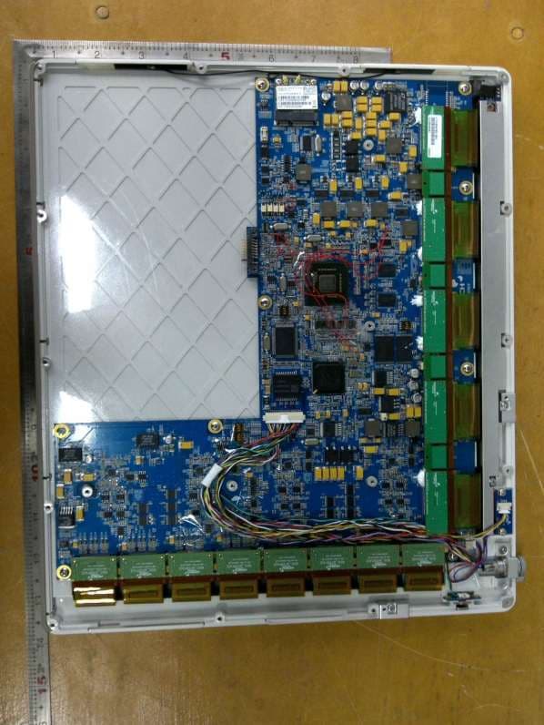
Click to zoom
Application Details
- Equipment Class
- NII - Unlicensed National Information Infrastructure TX
- Date of Grant
- Jan 29, 2013
- Application Purpose
- Original Equipment
- Date of Application
- Jan 29, 2013
- Equipment Note
- Medical Image Processing Unit
- Frequency Range
- 5180.00000000 - 5240.00000000
- Company
- Rayence Co., Ltd.
- Country
- South Korea
Documents & Files
Document Text
Text extracted from the exhibit documents filed with the FCC. Open a document above to read the original.
Users Manual
Release Version 1.0.6 Medical Image Processing Unit 1012WCA User Manual R-M-011-121030 © Copyright 2012, Rayence Co. Ltd. All pages of this document contain proprietary and confidential information of Rayence Corporation and are intended for exclusive use by Rayence Corporation personnel or customers. Copying, disclosure to others or other use is prohibited without the express written authorization from Rayence Corporation. Please report any violations of requirement to Rayence Corporation. R-M-011-121030 Attention For improvement of product performance, supplementation, or follow-up of information; the contents of this manual are subject to change without separate prior notice. Please note that our company has neither responsibility for any accidents nor obligation to do free repair service for any damage of the equipment due to user's mistake, which resulted from failure to follow the contents in this manual. Make sure to be familiar with the safety precautions and usage procedures. Also note that the product may slightly differ from the contents of this manual depending on specification. The following marks are used for the effective use of the product in this manual. Attention, consult accompanying documents. This is used to emphasize essential information. Be sure to read this information to avoid incorrect operation. This indicates hazardous situation which, if not heeded, may result in minor or moderate injury to you or others, or may result in machine damage. This indicates a potentially hazardous situation which, if not heeded, could result in death or serious injury to you or others. Federal Law restricts this device to sale by or the order of a radiologist or any other practitioners licensed by the law of the state in which that person practices to use or order the use of the device. R-M-011-121030 Contents Introduction ........................................................................................ 1 Intended use ...................................................................................... 1 Product features ................................................................................ 2 Product components ......................................................................... 3 Components Description................................................................... 5 Warning .............................................................................................. 8 Caution ............................................................................................. 10 Marking and labeling symbols ........................................................ 12 Notes for Using the Detector ............................................................ 14 Preparing .......................................................................................... 14 Handling ........................................................................................... 15 Handle Assembly ............................................................................. 15 Before Exposure .............................................................................. 17 During Exposure .............................................................................. 17 Limit of Load .................................................................................... 19 Disinfection and Cleaning ............................................................... 20 Others ............................................................................................... 20 Technical Features ........................................................................... 21 Mechanical Features ........................................................................ 21 Electrical Features ........................................................................... 21 Environmental requirement ............................................................. 24 PC Requirements ............................................................................. 24 Installation........................................................................................ 25 General interface ............................................................................. 25 Connection ....................................................................................... 25 IP set up ........................................................................................... 31 Using Web Manager (IP, SSID Change / Upgrade FW) ................... 32 Calibration ........................................................................................ 36 General Principle ............................................................................. 36 Calibration ........................................................................................ 38 Image Acquisition Test ..................................................................... 43 Program setup ................................................................................. 43 Get Image ......................................................................................... 44 View Images ..................................................................................... 45 Operation .......................................................................................... 50 Recommend ..................................................................................... 50 Switching power on / off .................................................................. 50 Storage ............................................................................................. 50 Information ....................................................................................... 51 Safety standard ................................................................................ 51 Electromagnetic Compatibility Information .................................... 53 FCC Notice ....................................................................................... 53 Main…
Text truncated - open the document above for the full version.
Users Manual
32 R-M-011-121030 Using Web Manager (IP, SSID Change / Upgrade FW) Change IP Address of Detector A. Turn on Detector and connect to PC (wired connection is recommended) B. After detector boot up, Launch web-browser (Optimized for Chrome/Internet Explorer) C. Connect to “http://[Detector’s IP]“ D. Select IP address to change from drop-down menu 33 R-M-011-121030 E. Click “SUBMIT” F. Restart detector(Turn Off then On) Change SSID and PSK(Pre-Shared Key) A. Turn on Detector and connect to PC (wired connection is recommended) B. After detector boot up, Launch web-browser (Optimized for Chrome/Internet Explorer) C. Connect to “http://[Detector’s IP]“ D. Select SSID to set (This value should match to Router’s setting) 34 R-M-011-121030 E. Type Pre-Shared Key to set (Password) (This value should match to Router’s setting Default:project302 ) F. Click “SUBMIT” G. Restart detector(Turn Off then On) Upgrade Firmware A. Turn on Detector and connect to PC (wired connection is recommended) 35 R-M-011-121030 B. After detector boot up, Launch web-browser (Optimized for Chrome/Internet Explorer) C. Connect to “http://[Detector’s IP]“ D. Select firmware file by click “Choose File” button. (Released file is named ‘fw_ppc’) E. Click ‘Upload File’ button F. Click ‘Flash Write’ button G. Restart detector(Turn Off then On) 36 R-M-011-121030 Calibration General Principle Notation Calibration can be done by image acquisition S/W. The gain- offset correction (under calibration) will be done with one dark, at least one bright and object frame. Parameter Description Offset Dark image, acquired image without X-ray exposure Bright Acquired image with X-ray exposure Object Bright image with object, will be calibrated Gain Gain of imaging system, offset subtracted image Offset correction Offset subtract Gain correction Compensate gain variance of pixel X-ray detector should be used at stable state within driving temperature range. Acquire the X-ray images after power on and 5 minutes warming up to obtain high quality images. 37 R-M-011-121030 Bright Calibration Point To gain correction, bright frame and dark frame should be acquired. The dark frame is needed only one frame. The bright frame is recommended to be acquired more than 8 different levels of median values of bright frames. The X-ray source condition will be recommended the tube energy level of 70kVp with variable tube current and exposure time. To acquire at least 3 frames at same condition will be recommended. The median values of bright frames are below. (Additional 21mm Al filter is recommended for calibration) The Purpose of Bright Calibration The center of the non calibrated image is brighter than the edge due to hill effect of X-ray exposure. Generally, the intensity of X- ray flux at center region of exposed area is higher than surroundings due to the X-ray expose like cone shape. A calibration process is used to compensate for this effect. Generally, called it ‘Flat Field Correction’(Bright calibration). Point 1 2 3 4 5 6 7 8 Median Value [LSB] 500 ~ 1500 4500~ 5500 9500 ~ 10500 14500 ~ 15500 19500~ 20500 24500 ~ 25500 29500 ~ 30500 34500~ 35500 The calibration range of bright is can be select by which exposure level is maximum level that user want to use. If the maximum level of user want to use is ‘20000’ in this case the level is contained in Bright point of ‘4’(refer ‘Table 5 : Median value’). The meaning is you don’t have to make bright point for ‘5’ and ‘6’(In this case, it will be does not working if you get image on higher level than maximum bright point.) 38 R-M-011-121030 Calibration Describe the calibration step by step. 1st Step Move to “Calibration” tap, and push “Get Dark” button. Acquire dark frame, the “dark.raw” will be generated at “\cal\” folder. 39 R-M-011-121030 2nd Step Push “Get Bright” button at different six of X-ray condition. The X- ray condition should be set or tested before, same as the level of ‘1.2’. Push “Get Bright” button at least 3 times at same condition, and then the offset subtracted bright (gain) is generated which of filename is “xNNNNNA.raw(Refer to NOTE) Click button [Get Bright]. It will produce frame with name %CAL% xNNNNNA.raw, where NNNNN is median pixel’s value within current image borders after offset calibration (cut frame edges are never used during calibration). Suffix ‘A’ (it also could be ‘B’,’C’ etc) avoids casual coincidence of file names. 40 R-M-011-121030 3rd step After 2 nd step, the “Generate” button will be activated. Click the button “Generate”, and then calibration point will be generated which of file name is “A ‘# of point’_ ‘median value of generated point’” like file of bright frame. The acquired bright frames within tolerance value which is variance of median level of acquired bright frames will be averaged and generated to a calibration point. The tolerance value can be edited. After making calibration point the “Generate” button will be disabling. 41 R-M-011-121030 4th step After 3rd step, Change Bad Pixels Removal Tab, Click the button “Generate Auto BPM”, and then Defect Map will be generated which of file name is “BPM.raw “ at the “\cal\” folder. 42 R-M-011-121030 5th step For additional Defect correction, if “BPMM.raw” is existed at the install CD, copy to the “\cal\” folder. 6th step On Acquisition Tab. Check the box “Offset Calibration”, “Gain Calibration”, and “Bad Pix Map” for activate to each calibration and Bad Pixels Removal. Otherwise, it will does not working when going to pre-processing . 43 R-M-011-121030 Image Acquisition Test Program setup To acquire images, run _vadav.lnk program. Please set the following figures Detector’s IP : Wireless - 2.2.2.100 Wire – 2.2.2.101 Detector‘s number of ADC : 4 Detector’s size of image : 2080 X 2560 44 R-M-011-121030 Get Image On Acquisition tab, click the “Get Image” button to get image. After click the button, you can see pop-up window, which is display window time and process of acquiring image. 45 R-M-011-121030 View Ima…
Text truncated - open the document above for the full version.
Cover Letter(s)
ATTESTATION LETTER For FCC ID: PFRFXRD1417W Federal Communication Commission Equipment Authorization Division, Application Processing Branch 7435 Oakland Mills Road Columbia, MD 21048 September 12th, 2012 TO WHOM IT MAY CONCERN The company Rayence Co., Ltd as being manufacturer of model 1012WCA hereby states that the model uses a certified module with 2.4GHz & 5GHz bands (FCC ID: PPD-AR5BHB116) Best regards, Type Name: Keedock, Kim Title: Quality Manager
Cover Letter(s)
Date: September 25, 2012 Federal Communications Commission 7435 Oakland Mills Road Columbia MD 21046 c.c. Compliance Certification Services Certification Division 47173 Benicia Street Fremont, CA 94538, USA To whom it may concern: I, the undersigned, hereby authorize Ms. Misoh Kim/Application Examiner of UL-Korea, to act on our behalf in all manners relating to application for equipment authorization, including signing of all documents relating to these matters. Any and all acts carried out by Ms. Misoh Kim of UL- Korea on our behalf shall have the same effect as acts of our own. I, the undersigned, hereby certify that we are not subject to a denial of federal benefits, that includes FCC benefits, pursuant to Section 5301 of the Anti-Drug Abuse Act of 1988, 21 U.S.C. 853(a). In authorizing UL Korea as our agent, we still recognize that we are responsible to: a) comply with the relevant provisions of the certification program; b) make all necessary arrangements for the conduct of the evaluation, including provision for examining documentation and access to all areas, records (including internal audit reports) and personnel for the purposes of evaluation (e.g. testing, inspection, assessment, surveillance, reassessment) and resolution of complaints; c) make claims regarding certification only in respect of the scope for which certification has been granted; d) do not use our product certification in such a manner as to bring the Certification Division into disrepute and not make any statement regarding our product certification which the Certification Division may consider misleading or unauthorized; e) upon suspension or cancellation of certification, discontinue use of all advertising matter that contains any reference thereto and return any certification documents as required by the Certification Division; f) use certification only to indicate the products are certified as being in conformity with specified standards; g) endeavor to ensure that no certificate or report nor any part thereof is used in a misleading manner; h) ensure that any reference to our product certification in communication media such as documents, brochures or advertising, complies with the requirements of the Certification Division; i) keep a record of all complaints made known to the us relating to the product’s compliance with requirements of the relevant standard and to make these records available to the Certification Division when requested; j) take appropriate action with respect to such complaints and any deficiencies found in products or services that affect compliance with the requirements for certification; k) document the actions taken. This authorization is valid until further written notice from the applicant. Sincerely, Name & Title: Namyoung Ha / Assistant Manager Company name: Rayence Co., Ltd Email: [email protected] REMARK: 1. This authorization letter will be sent along with your application when filing with the Certification Division. 2. Please follow the format and type it on company letterhead and send original to us. 3. Authorized signature must be in agreement with grantee code contact in FCC database.
Cover Letter(s)
CONFIDENTIALITY REQUEST Federal Communication Commission Equipment Authorization Division, Application Processing Branch 7435 Oakland Mills Road Columbia, MD 21048 September 12th, 2012 TO WHOM IT MAY CONCERN Pursuant to Paragraphs §0.457 and 0.459 of the Commission’s Rules (47 C.F.R.) and Section §552(b)(4) of the Freedom of Information Act, Rayence Co., Ltd requests confidentiality for the following products: FCC ID/ Number Product Title/Model QIIRY1012WCA / Medical Image Processing Unit / 1012WCA The following exhibits contain trade secrets and proprietary information that could be of benefit to our competitors regarding the design of our product. This material is not customarily available to the general public and we request that it be withheld from public inspection. We request that the following information submitted be held permanent confidential treatment. Permanent Confidential Request - Schematics - Block diagram - Part List, BOM, Part Location - Operational Description Short-term Confidential Request (lead time: 45 days) - Antenna information - External photo - Internal photo - Service manual If you have any questions, please feel free to contact me at the address shown below. Best regards, Type Name: Namyoung Ha Title: Assistant Manager Company name: Rayence Co., Ltd
Cover Letter(s)
ATTESTATION FOR MODULE INCORPORATION Federal Communication Commission Equipment Authorization Division, Application Processing Branch 7435 Oakland Mills Road Columbia, MD 21048 January 8, 2013 TO WHOM IT MAY CONCERN The company Rayence Co., Ltd declare that the equipment under FCC authorization processing FCC ID : QIIRY1012WCA is incorporate Radio transmitter module which has been authorized by FCC as single modular transmitter, FCC ID : PPD-AR5BHB116. The end product (FCC ID : QIIRY1012WCA) will use the in original certified transmitter module and will keep the original authorization condition except the change in antenna of the module during the final end product assembly. Due to the change in antenna of the radio module, the host product FCC authorization is required. For the host product testing, we leveraged the modular report for the conducted test data because the original operating condition is applied to the end product without any changes such as max. RF output power and frequencies and other radio characteristics. So, we concluded that the below conducted test items of the radio module were considered as the same result in the end product. Radio module Items FCC ID : PPD-AR5BHB116 6dB bandwidth, Max.output power, Conducted spurious, Power spectral density All other characteristics related with radiated was evaluated in the final end product condition. Best regards, Company : Rayence Co., Ltd. Type Name: Keedock, Kim Title : Manager
Cover Letter(s)
ATTESTATION LETTER For FCC ID: QIIRY1012WCA Federal Communication Commission Equipment Authorization Division, Application Processing Branch 7435 Oakland Mills Road Columbia, MD 21048 January 18 th, 2013 TO WHOM IT MAY CONCERN The company Rayence Co., Ltd product 1012WCA (FCC ID: QIIRY1012WCA) in the RF module (FCC ID: PPD-AR5BHB116) does not use DFS band. Best regards, Company : Rayence Co., Ltd. Type Name: Keedock, Kim Title: Quality Manager
External Photos
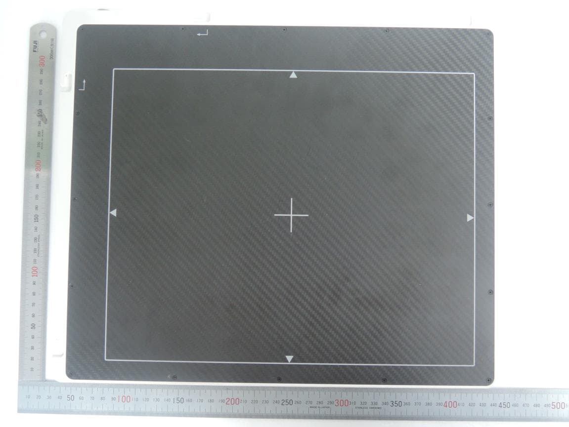
Project Number: 12CA50022 File Number : MC16901 Page : 1 of 10 Model Number: 1012WCA UL Korea, Ltd. 33 rd FL, Gangnam Finance Center, 737 Yeoksam-dong, Gangnam-gu, Seoul 135-984 Korea Tel: +82.2.2009.9000, Fax:+82.2.2009.9405 Report Version 1.2 June-06,2007 Only those products bearing the UL Mark should be considered as being covered by UL. EXTERNAL PHOTOS OF EUT Front View Project Number: 12CA50022 File Number : MC16901 Page : 2 of 10 Model Number: 1012WCA UL Korea, Ltd. 33 rd FL, Gangnam Finance Center, 737 Yeoksam-dong, Gangnam-gu, Seoul 135-984 Korea Tel: +82.2.2009.9000, Fax:+82.2.2009.9405 Report Version 1.2 June-06,2007 Only those products bearing the UL Mark should be considered as being covered by UL. Rear Project Number: 12CA50022 File Number : MC16901 Page : 3 of 10 Model Number: 1012WCA UL Korea, Ltd. 33 rd FL, Gangnam Finance Center, 737 Yeoksam-dong, Gangnam-gu, Seoul 135-984 Korea Tel: +82.2.2009.9000, Fax:+82.2.2009.9405 Report Version 1.2 June-06,2007 Only those products bearing the UL Mark should be considered as being covered by UL. Side View - Right Project Number: 12CA50022 File Number : MC16901 Page : 4 of 10 Model Number: 1012WCA UL Korea, Ltd. 33 rd FL, Gangnam Finance Center, 737 Yeoksam-dong, Gangnam-gu, Seoul 135-984 Korea Tel: +82.2.2009.9000, Fax:+82.2.2009.9405 Report Version 1.2 June-06,2007 Only those products bearing the UL Mark should be considered as being covered by UL. Side View - Left Project Number: 12CA50022 File Number : MC16901 Page : 5 of 10 Model Number: 1012WCA UL Korea, Ltd. 33 rd FL, Gangnam Finance Center, 737 Yeoksam-dong, Gangnam-gu, Seoul 135-984 Korea Tel: +82.2.2009.9000, Fax:+82.2.2009.9405 Report Version 1.2 June-06,2007 Only those products bearing the UL Mark should be considered as being covered by UL. APPENDIX C - INTERNAL PHOTOS OF EUT Inside Project Number: 12CA50022 File Number : MC16901 Page : 6 of 10 Model Number: 1012WCA UL Korea, Ltd. 33 rd FL, Gangnam Finance Center, 737 Yeoksam-dong, Gangnam-gu, Seoul 135-984 Korea Tel: +82.2.2009.9000, Fax:+82.2.2009.9405 Report Version 1.2 June-06,2007 Only those products bearing the UL Mark should be considered as being covered by UL. Mainboard Project Number: 12CA50022 File Number : MC16901 Page : 7 of 10 Model Number: 1012WCA UL Korea, Ltd. 33 rd FL, Gangnam Finance Center, 737 Yeoksam-dong, Gangnam-gu, Seoul 135-984 Korea Tel: +82.2.2009.9000, Fax:+82.2.2009.9405 Report Version 1.2 June-06,2007 Only those products bearing the UL Mark should be considered as being covered by UL. RF Module_ Front Project Number: 12CA50022 File Number : MC16901 Page : 8 of 10 Model Number: 1012WCA UL Korea, Ltd. 33 rd FL, Gangnam Finance Center, 737 Yeoksam-dong, Gangnam-gu, Seoul 135-984 Korea Tel: +82.2.2009.9000, Fax:+82.2.2009.9405 Report Version 1.2 June-06,2007 Only those products bearing the UL Mark should be considered as being covered by UL. RF Module_ Rear Project Number: 12CA50022 File Number : MC16901 Page : 9 of 10 Model Number: 1012WCA UL Korea, Ltd. 33 rd FL, Gangnam Finance Center, 737 Yeoksam-dong, Gangnam-gu, Seoul 135-984 Korea Tel: +82.2.2009.9000, Fax:+82.2.2009.9405 Report Version 1.2 June-06,2007 Only those products bearing the UL Mark should be considered as being covered by UL. RF Module_ Installation Project Number: 12CA50022 File Number : MC16901 Page : 10 of 10 Model Number: 1012WCA UL Korea, Ltd. 33 rd FL, Gangnam Finance Center, 737 Yeoksam-dong, Gangnam-gu, Seoul 135-984 Korea Tel: +82.2.2009.9000, Fax:+82.2.2009.9405 Report Version 1.2 June-06,2007 Only those products bearing the UL Mark should be considered as being covered by UL. Battery Label
ID Label/Location Info
Project Number: 12CA50022 File Number : MC16901 Page : 1 of 1 Model Number: 1012WCA UL Korea, Ltd. 33 rd FL, Gangnam Finance Center, 737 Yeoksam-dong, Gangnam-gu, Seoul 135-984 Korea Tel: +82.2.2009.9000, Fax:+82.2.2009.9405 Report Version 1.2 June-06,2007 Only those products bearing the UL Mark should be considered as being covered by UL. Label Information of EUT
Internal Photos
Project Number: 12CA50022 File Number : MC16901 Page : 1 of 6 Model Number: 1012WCA UL Korea, Ltd. 33 rd FL, Gangnam Finance Center, 737 Yeoksam-dong, Gangnam-gu, Seoul 135-984 Korea Tel: +82.2.2009.9000, Fax:+82.2.2009.9405 Report Version 1.2 June-06,2007 Only those products bearing the UL Mark should be considered as being covered by UL. INTERNAL PHOTOS OF EUT Inside Project Number: 12CA50022 File Number : MC16901 Page : 2 of 6 Model Number: 1012WCA UL Korea, Ltd. 33 rd FL, Gangnam Finance Center, 737 Yeoksam-dong, Gangnam-gu, Seoul 135-984 Korea Tel: +82.2.2009.9000, Fax:+82.2.2009.9405 Report Version 1.2 June-06,2007 Only those products bearing the UL Mark should be considered as being covered by UL. Mainboard Project Number: 12CA50022 File Number : MC16901 Page : 3 of 6 Model Number: 1012WCA UL Korea, Ltd. 33 rd FL, Gangnam Finance Center, 737 Yeoksam-dong, Gangnam-gu, Seoul 135-984 Korea Tel: +82.2.2009.9000, Fax:+82.2.2009.9405 Report Version 1.2 June-06,2007 Only those products bearing the UL Mark should be considered as being covered by UL. RF Module_ Front Project Number: 12CA50022 File Number : MC16901 Page : 4 of 6 Model Number: 1012WCA UL Korea, Ltd. 33 rd FL, Gangnam Finance Center, 737 Yeoksam-dong, Gangnam-gu, Seoul 135-984 Korea Tel: +82.2.2009.9000, Fax:+82.2.2009.9405 Report Version 1.2 June-06,2007 Only those products bearing the UL Mark should be considered as being covered by UL. RF Module_ Rear Project Number: 12CA50022 File Number : MC16901 Page : 5 of 6 Model Number: 1012WCA UL Korea, Ltd. 33 rd FL, Gangnam Finance Center, 737 Yeoksam-dong, Gangnam-gu, Seoul 135-984 Korea Tel: +82.2.2009.9000, Fax:+82.2.2009.9405 Report Version 1.2 June-06,2007 Only those products bearing the UL Mark should be considered as being covered by UL. RF Module_ Installation Project Number: 12CA50022 File Number : MC16901 Page : 6 of 6 Model Number: 1012WCA UL Korea, Ltd. 33 rd FL, Gangnam Finance Center, 737 Yeoksam-dong, Gangnam-gu, Seoul 135-984 Korea Tel: +82.2.2009.9000, Fax:+82.2.2009.9405 Report Version 1.2 June-06,2007 Only those products bearing the UL Mark should be considered as being covered by UL. Battery Label
Parts List/Tune Up Info
Rayence 2012-01 Antenna PCB Dual-Band Antenna (Wi-Fi 2.4/5GHz) PRODUCT APPROVAL SHEET Version : 1.2 SuppliersCustomer WriterReviewApprovalApproved by 품명Rayence 2012-01 Dual Band PCB Antenna Part Number AEi-2450/5500DP-C1.13 [Rayence] DescriptionDual-Band(2.4/5GHz) /PCB /I-Pex SalesRodem Microsystem D RODEM MICROSYSTEM CO., LTD. (448-808) #401, Sangsaeng B/D, 253-1, Jukjeon-ro, Suji-gu, Yongin-si, Gyeonggi-do, KOREA Office : +82-31-715-9309 | Fax : +82-505-329-9309 E-mail :[email protected]| Website :www.rodemsys.co.kr (주)레이언스 2 Revised History Rayence 2012-01 Antenna - PRODUCT APPROVAL SHEET VersionPurposeDateEditor V 1.0Initial Doc2012/05/09배재균 V 1.12 nd Rework & Test2012/07/03배재균 V 1.2 Appendix-A (Correlated & Uncorrelated) 2013/01/18배재균 3 1. SPECIFICATION ELECTRICAL SPECIFICATIONS MODEL AEi-2450/5500DP-C1.13 [Rayence] (MHz)2.4~2.5GHz / 5.2~5.8GHGz V.S.W.RLESS THAN 1 : 5.0 GAIN(dBi) - 2.4GHz2.8dBi (MIMO Gain : 2.8+10log[2] = 5.81dBi) GAIN(dBi) - 5.8GHz3.66dBi(MIMO Gain : 3.66+10log[2] = 6.67dBi) Radiation PatternOMNI-DIRECTIONAL POLARIZATIONVERTICAL MECHANICAL SPECIFICATIONS SPECREMARK MOUNT TYPE3M TAPEATTACHED RADIATION TYPEDipole PCB CONNECTOR TYPEU.FLGOLD-PLATING CABLE1.13ĭ/70,90mmBLACK-Color MATERIALFR-4, 0.8T DIMENSION50x9x0.8 mm OPERATING TEMPERATURE(°C)-30°~+70° 1. 품명 : AEi2450/5500DP-C1.13 2. 적용 : 본 사양서는 WiFi용 듀얼밴드 PCB ANTENNA에 대해 규정한다. 3. ANTENNA 사용 조건 □휴대 ■고정 □이동 □실외 ■실내 □기타 ( ) 4. ANTENNA 형상 첨부 도면과 같음. 5. 전기적 특성 및 성능 실 사용조건 또는 그에 상응하는 적합한 상태에서 다음을 만족 할 것. Rayence 2012-01 Antenna - PRODUCT APPROVAL SHEET 6. 기구적 사양 및 특성 4 7. 기타성능및특성 7.1 내진성(耐振性) ANTENNA를 SET에 결합한 상태로, 전진폭 1mm, 진동수 5-55Hz를 1분간 나누어 변화시키는 진동을 상하, 좌우, 전후 방향으로 2시간씩 가한 후 측 정하여, 각 부위에 이탈 등의 이상이 없고, 5항의 특성 및 성능을 만족할 것. 7.2 내온성( 耐溫性) ANTENNA를 -30°C 및 70°C에 각각 96시간 방치한 후 측정하여 각부의 이탈, 변형 등의 이상이 없고, 5항의 특성 및 성능을 만족할 것. 7.3 내습성( 耐濕性) ANTENNA를 주위온도 40°C, 상태습도 90~95%에 96시간 방치한 후, 상온상습 상태에서 측정하여 외관, 각부의 구조에 이상이 없고, 5항의 특성 및 성능을 만 족할 것. 8. 측정 및 검사 본 사양서에 정해진 사항 및 승인원상의 요구사항에 따르고, 당사 품질관리규 정에 적합 할 것. 단 7항의 사항은 발주자의 협의에 의해 생략할 수 있음. 9. 포 장 제품의 포장은 개별 포장 후, 적당한 BOX에 유동이 없도록 집합 포장한다. 10. 보 증 본 제품은 납입 후 1년 이내에, 설계 또는 제작상의 불량이라고 판단되는 결함 이 발생하였을 경우, 즉시 무상 수리 또는 교환해 줄 의무가 있다. Rayence 2012-01 Antenna - PRODUCT APPROVAL SHEET 5 2. Measuerement 2.1. 3D-Measurement -. 안테나의 이득과 복사 패턴을 측정하는 장면 및 3D 복사 패턴을 측정하기 위한 안테나의 설치. -. Calibration 주파수 대역 : 2.4 ~ 6.0[GHz] -. 2D 복사패턴 Angle step : 05° -. 3D 복사패턴 Angle step : 15° Rayence 2012-01 Antenna - PRODUCT APPROVAL SHEET 6 3.1. Radiation Pattern / 상측-2.4GHz 3. SPEC Data Rayence 2012-01 Antenna - PRODUCT APPROVAL SHEET 7 3.2 Radiation Pattern / 상측-5GHz 3. SPEC Data Rayence 2012-01 Antenna - PRODUCT APPROVAL SHEET 8 3.3. Radiation Pattern / 하측2.4GHz 3. SPEC Data Rayence 2012-01 Antenna - PRODUCT APPROVAL SHEET 9 3.4. Radiation Pattern / 하측5GHz 3. SPEC Data Rayence 2012-01 Antenna - PRODUCT APPROVAL SHEET 10 4. 입력임피던스정합도(반사손실) 4. INPUT Impedance <4.1 상측안테나> <4.2 하측안테나> Rayence 2012-01 Antenna - PRODUCT APPROVAL SHEET 11 5. Antenna Dimension Rayence 2012-01 Antenna - PRODUCT APPROVAL SHEET 12 6. Antenna Image Rayence 2012-01 Antenna - PRODUCT APPROVAL SHEET
RF Exposure Info
UL Korea, Ltd An organization dedicated 33 rd FL, Gangnam Finance Center, 737 to public safety and committed to Yeoksam-dong, Gangnam-gu, Seoul quality service for over 100 years 135-984 Korea Tel: +82.2.2009.9000, Fax:+82.2.2009.9405 Underwriters Laboratories Inc. www.ul.com/emc www.ulk.co.kr Project No.: 12CA50022 File No.: MC16901 Report No.: 12CA50022-8-FCC Date: November 6, 2012 Model No.: 1012WCA FCC ID.: QIIRY1012WCA FCC Maximum Permissible Exposure Report in accordance with FCC Part 1 Subpart I §1.1307(b) & §1.1310 for Medical Image Processing Unit (Telemetry System Transmitter) RAYENCE CO., LTD 1F, 2F, 3F, #402, 14, Samsung 1ro 1-gil, Hwaseong-si, Gyeonggi-do, 445-170, Korea Copyright 2005 Underwriters Laboratories Inc. Underwriters Laboratories Inc. authorizes the above-named company to reproduce this Report provided it is reproduced in its entirety. Only those products bearing the UL Mark should be considered as being covered by UL. Project Number: 12CA50022 File Number : MC16901 Page : 2 of 14 Model Number: 1012WCA UL Korea, Ltd. 33 rd FL, Gangnam Finance Center, 737 Yeoksam-dong, Gangnam-gu, Seoul 135-984 Korea Tel: +82.2.2009.9000, Fax:+82.2.2009.9405 Report Version 1.2 June-06,2007 Only those products bearing the UL Mark should be considered as being covered by UL. Summary of Test Results: The following tests were performed on a sample submitted for evaluation of compliance with FCC Part 1 Subpart I Section 1.1307(b) & 1.1310 No Reference Clause No. Conformance Requirements Result Verdict Remark 1 1.1307(b)(1) 1.1310 Maximum Permissible Exposure (Exposure of Humans to RF Fields) Complied Conclusion: The tests listed in the Summary of Testing section of this report have been performed and the results recorded by UL Korea Ltd. in accordance with the procedures stated in each test requirement and specification. The test list was determined by the Applicant as bei…
Text truncated - open the document above for the full version.
Contact Information
Applicant
Minju Choi(Assistant Manager)
Test Firm
SPORTON International Inc.Alex Chen
Technical Specifications
| # | Rule Parts | Frequency Range | Power Output |
|---|---|---|---|
| 1 | 15E | 5.18 GHz - 5.24 GHz | 48.30 mW |
Other Applications from Rayence Co., Ltd.
QIIRY1012WA
Nov 12, 2015Medical Image Processing Unit
Equipment Class
DTS - Digital Transmission System
QIIRY1012WGB
Sep 15, 2015Industrial Image Processing Unit
Equipment Class
DTS - Digital Transmission System
QIIRY1417W
Jul 23, 2014Medical Image Processing Unit
Equipment Class
NII - Unlicensed National Information Infrastructure TX
QIIRY1417WGB
Mar 31, 2014Industrial Image Processing Unit
Equipment Class
NII - Unlicensed National Information Infrastructure TX
QIIRY1417WGA
Apr 07, 2013Medical Image Processing Unit
Equipment Class
DTS - Digital Transmission System