QIPHMS1Quadband GSM/GPRS/UMTS/HSDPA Module
Telit Cinterion Deutschland GmbH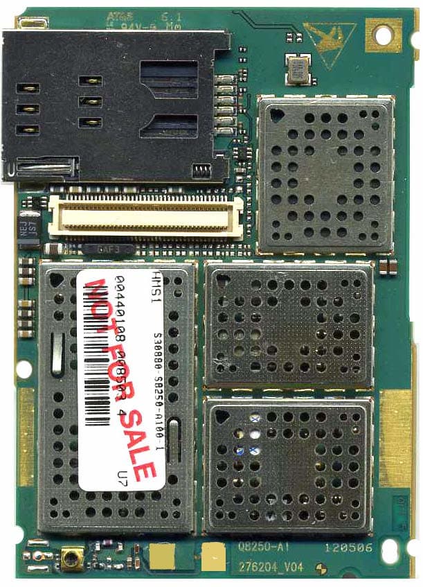
Click to zoom
Application Details
- Equipment Class
- PCB - PCS Licensed Transmitter
- Date of Grant
- Oct 16, 2006
- Application Purpose
- Original Equipment
- Date of Application
- Oct 16, 2006
- Equipment Note
- Quadband GSM/GPRS/UMTS/HSDPA Module
- Frequency Range
- 824.20000000 - 848.80000000
- Country
- Germany
Documents & Files
Document Text
Text extracted from the exhibit documents filed with the FCC. Open a document above to read the original.
Users Manual
Hardware Interface Descri p tion HMS1 Siemens Cellular Engine Version: 01.62 DocID: HMS1_HD_V01.62 HMS1 Hardware Interface Description Confidential / Preliminary s HMS1_HD_V01.62 Page 2 of 39 2006-08-21 Document Name: HMS1 Hardware Interface Description Version: 01.62 Date: August 21, 2006 DocId: HMS1_HD_V01.62 Status: Confidential / Preliminary General note Product is deemed accepted by Recipient and is provided without interface to Recipient ́s products. The Product constitutes pre-release version and code and may be changed substantially before commercial release. The Product is provided on an “as is” basis only and may contain deficiencies or inadequacies. The Product is provided without warranty of any kind, express or implied. To the maximum extent permitted by applicable law, Siemens further disclaims all warranties, including without limitation any implied warranties of merchantability, fitness for a particular purpose and noninfringement of third-party rights. The entire risk arising out of the use or performance of the Product and documentation remains with Recipient. This Product is not intended for use in life support appliances, devices or systems where a malfunction of the product can reasonably be expected to result in personal injury. Applications incorporating the described product must be designed to be in accordance with the technical specifications provided in these guidelines. Failure to comply with any of the required procedures can result in malfunctions or serious discrepancies in results. Furthermore, all safety instructions regarding the use of mobile technical systems, including GSM products, which also apply to cellular phones must be followed. Siemens AG customers using or selling this product for use in any applications do so at their own risk and agree to fully indemnify Siemens for any damages resulting from illegal use or resale. To the maximum extent permitted by applicable law, in no event shall Siemens or its suppliers be liable for any consequential, incidental, direct, indirect, punitive or other damages whatsoever (including, without limitation, damages for loss of business profits, business interruption, loss of business information or data, or other pecuniary loss) arising out the use of or inability to use the Product, even if Siemens has been advised of the possibility of such damages. Subject to change without notice at any time. Copyright Transmittal, reproduction, dissemination and/or editing of this document as well as utilization of its contents and communication thereof to others without express authorization are prohibited. Offenders will be held liable for payment of damages. All rights created by patent grant or registration of a utility model or design patent are reserved. Copyright © Siemens AG 2006 HMS1 Hardware Interface Description Confidential / Preliminary s HMS1_HD_V01.62 Page 3 of 39 2006-08-21 Contents 0. Document History ......................................................................................................5 1. Introduction ................................................................................................................6 1.1. Related Documents.............................................................................................6 1.2. Terms and Abbreviations ....................................................................................6 1.3. Type Approval .....................................................................................................9 1.4. Safety Precautions ............................................................................................11 2. Product Concept ......................................................................................................13 2.1. Key Features at a Glance..................................................................................13 2.2. HMS1 System Overview ...................................................................................15 2.3. Circuit Concept..................................................................................................16 3. Application Interface................................................................................................17 3.1. Operating Modes...............................................................................................18 3.2. Power Supply....................................................................................................19 3.2.1. Minimizing Power Losses ....................................................................19 3.3. Power-Up / Power-Down Scenarios ..................................................................20 3.3.1. Turn on HMS1 .....................................................................................20 3.3.2. Turn off HMS1 .....................................................................................20 3.4. Power Saving ....................................................................................................21 3.5. RTC Backup......................................................................................................21 3.6. USIM Interface ..................................................................................................21 3.7. USB Interface....................................................................................................21 3.8. Control Signals..................................................................................................22 3.8.1. PWR_IND Signal .................................................................................22 3.8.2. Status Signals .....................................................................................22 4. Antenna Interface .....................................................................................................23 4.1. Antenna Installation...........................................................................................23 4.1.1. Test Antenna.................…
Text truncated - open the document above for the full version.
External Photos
Siemens Cellular Engine HMS1 Top side Siemens Cellular Engine HMS1 Top side without shielding Siemens Cellular Engine HMS1 Bottom Side
Internal Photos
Siemens Cellular Engine HMS1 Top side Siemens Cellular Engine HMS1 Top side without shielding Siemens Cellular Engine HMS1 Bottom Side
Test Report
7 layers AG Aufsichtsratsvorsitzenderh Registergerichth registered in: Borsigstrasse 11 Chairman of the Supervisory Board: Düsseldorf, HRB 44096 40880 Ratingen, Germany Markus Becker USt-IdNr h VAT Nr: Phone: +49 (0) 2102 749 0 Vorstandh Board: DE 203159652 Fax: +49 (0) 2102 749 350 Dr. Hans-Jürgen Meckelburg www.7Layers.com René Schildknecht InterLab ® is a registered trademark of 7 layers AG FCC Measurement/Technical Report on GSM/UMTS Module Siemens HMS1 Report Reference: 4_Siem_0706_UMTS_FCCa Test Laboratory: 7 layers AG Borsigstrasse 11 40880 Ratingen Germany email: [email protected] DAT-P-192/99-01 Note: The following test results relate only to the devices specified in this document. This report shall not be reproduced in parts without the written approval of the testing laboratory. Test report Reference: 4_Siem_0706_UMTS_FCCa Page 2 of 56 Table of Contents 0 Summary 3 0.1 Technical Report Summary 3 0.2 Measurement Summary 4 1 Administrative Data 6 1.1 Testing Laboratory 6 1.2 Project Data 6 1.3 Applicant Data 6 1.4 Manufacturer Data 6 2 Testobject Data 7 2.1 General EUT Description 7 2.2 EUT Main components 8 2.3 Ancillary Equipment 8 2.4 EUT Setups 8 2.5 Operating Modes 9 3 Test Results 10 3.1 RF Power Output 10 3.2 Frequency stability 14 3.3 Spurious emissions at antenna terminals 18 3.4 Field strength of spurious radiation 22 3.5 Emission and Occupied Bandwidth 26 3.6 Band edge compliance 30 4 Test Equipment 32 5 Photo Report 35 6 Setup Drawings 39 7 Annex 41 Measurement Plots Test report Reference: 4_Siem_0706_UMTS_FCCa Page 3 of 56 0 Summary 0.1 Technical Report Summary Type of Authorization Certification for a GSM cellular radiotelephone device Applicable FCC Rules Prepared in accordance with the requirements of FCC Rules and Regulations as listed in 47 CFR Ch.1 Parts 0 to 19 and Parts 20 to 69 (10-1-05 Edition). The following subparts are applicable to the results in this test report. Part 2 Subpart J - Equipment Authorization Procedures, Certification § 2.1046 Measurement required: RF power output § 2.1049 Measurement required: Occupied bandwidth § 2.1051 Measurement required: Spurious emissions at antenna terminals § 2.1053 Measurement required: Field strength of spurious radiation § 2.1055 Measurement required: Frequency stability § 2.1057 Frequency spectrum to be investigated Part 22 Subpart C – Operational and Technical Requirements § 22.355 Frequency tolerance Subpart H – Cellular Radiotelephone Service § 22.913 Effective radiated power limits § 22.917 Emission limitations for cellular equipment Summary Test The EUT complied with all performed tests as listed in chapter 0.2 Measurement Summary. Test report Reference: 4_Siem_0706_UMTS_FCCa Page 4 of 56 0.2 Measurement Summary RF Power Output The measurement was performed according to FCC §2.1046 10-1-05 OP-Mode Setup Port Final Result op-mode 1 Setup_a01 antenna connector passed op-mode 2 Setup_a01 antenna connector passed op-mode 3 Setup_a01 antenna connector passed op-mode 4 Setup_a01 antenna connector passed op-mode 5 Setup_a01 antenna connector passed op-mode 6 Setup_a01 antenna connector passed Frequency stability The measurement was performed according to FCC §2.1055 10-1-05 OP-Mode Setup Port Final Result op-mode 2 Setup_a01 antenna connector passed op-mode 5 Setup_a01 antenna connector passed Spurious emissions at antenna terminals The measurement was performed according to FCC §2.1051 10-1-05 OP-Mode Setup Port Final Result op-mode 1 Setup_a01 antenna connector passed op-mode 2 Setup_a01 antenna connector passed op-mode 3 Setup_a01 antenna connector passed op-mode 4 Setup_a01 antenna connector passed op-mode 5 Setup_a01 antenna connector passed op-mode 6 Setup_a01 antenna connector passed Field strength of spurious radiation The measurement was performed according to FCC §2.1053 10-1-05 OP-Mode Setup Port Final Result op-mode 1 Setup_a01 enclosure passed op-mode 2 Setup_a01 enclosure passed op-mode 3 Setup_a01 enclosure passed op-mode 4 Setup_a01 enclosure passed op-mode 5 Setup_a01 enclosure passed op-mode 6 Setup_a01 enclosure passed Emission and Occupied Bandwidth The measurement was performed according to FCC §2.1049 10-1-05 OP-Mode Setup Port Final Result op-mode 1 Setup_a01 antenna connector passed op-mode 2 Setup_a01 antenna connector passed op-mode 3 Setup_a01 antenna connector passed op-mode 4 Setup_a01 antenna connector passed op-mode 5 Setup_a01 antenna connector passed op-mode 6 Setup_a01 antenna connector passed Test report Reference: 4_Siem_0706_UMTS_FCCa Page 6 of 56 1 Administrative Data 1.1 Testing Laboratory Company Name: 7 Layers AG Address Borsigstr. 11 40880 Ratingen Germany This facility has been fully described in a report submitted to the FCC and accepted under the registration number 96716 . The test facility is also accredited by the following accreditation organisation: - Deutscher Akkreditierungs Rat DAR-Registration no. DAT-P-192/99-01 Responsible for Accreditation Scope: Dipl.-Ing. Bernhard Retka Dipl.-Ing. Robert Machulec Dipl.-Ing. Thomas Hoell Report Template Version: 2006-08-31 1.2 Project Data Responsible for testing and report: Dipl.-Ing. Andreas Petz Receipt of EUT: 2006-07-28 Date of Test(s): 2006-07-29 to 2006-09-05 Date of Report: 2006-09-25 1.3 Applicant Data Company Name: Siemens AG Address: Siemensdamm 50 13629 Berlin Germany Contact Person: Mr. Thorsten Liebig 1.4 Manufacturer Data Company Name: please see applicant data Address: Contact Person: Test report Reference: 4_Siem_0706_UMTS_FCCa Page 7 of 56 2 Testobject Data 2.1 General EUT Description Equipment under Test: GSM/UMTS Module Type Designation: Siemens HMS1 Kind of Device: (optional) GSM 850/900/1800/1900 and UMTS FDDI module Voltage Type: DC Nominal Voltage: 3.6 V Maximum Voltage: – Minimum Voltage: – General product description: The Equipment Under Test (EUT) is a GSM 850/900/1800/1900 module and supports GSM and EDGE mode and FDD I. The manufacturer declared that nominal voltage is equal to minimum as well …
Text truncated - open the document above for the full version.
Test Report
7 layers AG Aufsichtsratsvorsitzenderh Registergerichth registered in: Borsigstrasse 11 Chairman of the Supervisory Board: Düsseldorf, HRB 44096 40880 Ratingen, Germany Markus Becker USt-IdNr h VAT Nr: Phone: +49 (0) 2102 749 0 Vorstandh Board: DE 203159652 Fax: +49 (0) 2102 749 350 Dr. Hans-Jürgen Meckelburg www.7Layers.com René Schildknecht InterLab ® is a registered trademark of 7 layers AG FCC Measurement/Technical Report on GSM/UMTS Module Siemens HMS1 Report Reference: 4_Siem_0706_UMTS_FCCb Test Laboratory: 7 layers AG Borsigstrasse 11 40880 Ratingen Germany email: [email protected] DAT-P-192/99-01 Note: The following test results relate only to the devices specified in this document. This report shall not be reproduced in parts without the written approval of the testing laboratory. Test report Reference: 4_Siem_0706_UMTS_FCCb Page 2 of 56 Table of Contents 0 Summary 3 0.1 Technical Report Summary 3 0.2 Measurement Summary 4 1 Administrative Data 6 1.1 Testing Laboratory 6 1.2 Project Data 6 1.3 Applicant Data 6 1.4 Manufacturer Data 6 2 Testobject Data 7 2.1 General EUT Description 7 2.2 EUT Main components 8 2.3 Ancillary Equipment 8 2.4 EUT Setups 8 2.5 Operating Modes 9 3 Test Results 10 3.1 RF Power Output 10 3.2 Frequency stability 14 3.3 Spurious emissions at antenna terminals 18 3.4 Field strength of spurious radiation 22 3.5 Emission and Occupied Bandwidth 26 3.6 Band edge compliance 30 4 Test Equipment 32 5 Photo Report 35 6 Setup Drawings 39 7 Annex 41 Measurement Plots Test report Reference: 4_Siem_0706_UMTS_FCCb Page 3 of 56 0 Summary 0.1 Technical Report Summary Type of Authorization Certification for a GSM cellular radiotelephone device Applicable FCC Rules Prepared in accordance with the requirements of FCC Rules and Regulations as listed in 47 CFR Ch.1 Parts 0 to 19 and Parts 20 to 69 (10-1-05 Edition). The following subparts are applicable to the results in this test report. Part 2 Subpart J - Equipment Authorization Procedures, Certification § 2.1046 Measurement required: RF power output § 2.1049 Measurement required: Occupied bandwidth § 2.1051 Measurement required: Spurious emissions at antenna terminals § 2.1053 Measurement required: Field strength of spurious radiation § 2.1055 Measurement required: Frequency stability § 2.1057 Frequency spectrum to be investigated Part 24 Subpart E - Broadband PCS § 24.232 Power and antenna height limits § 24.235 Frequency stability § 24.236 Field strength limits § 24.238 Emission limitations for Broadband PCS equipment Summary Test Results: The EUT complied with all performed tests as listed in chapter 0.2 Measurement Summary. Test report Reference: 4_Siem_0706_UMTS_FCCb Page 4 of 56 0.2 Measurement Summary RF Power Output The measurement was performed according to FCC §2.1046 10-1-05 OP-Mode Setup Port Final Result op-mode 1 Setup_a01 antenna connector passed op-mode 2 Setup_a01 antenna connector passed op-mode 3 Setup_a01 antenna connector passed op-mode 4 Setup_a01 antenna connector passed op-mode 5 Setup_a01 antenna connector passed op-mode 6 Setup_a01 antenna connector passed Frequency stability The measurement was performed according to FCC §2.1055 10-1-05 OP-Mode Setup Port Final Result op-mode 2 Setup_a01 antenna connector passed op-mode 4 Setup_a01 antenna connector passed Spurious emissions at antenna terminals The measurement was performed according to FCC §2.1051 10-1-05 OP-Mode Setup Port Final Result op-mode 1 Setup_a01 antenna connector passed op-mode 2 Setup_a01 antenna connector passed op-mode 3 Setup_a01 antenna connector passed op-mode 4 Setup_a01 antenna connector passed op-mode 5 Setup_a01 antenna connector passed op-mode 6 Setup_a01 antenna connector passed Field strength of spurious radiation The measurement was performed according to FCC §2.1053 10-1-05 OP-Mode Setup Port Final Result op-mode 1 Setup_a01 enclosure passed op-mode 2 Setup_a01 enclosure passed op-mode 3 Setup_a01 enclosure passed op-mode 4 Setup_a01 enclosure passed op-mode 5 Setup_a01 enclosure passed op-mode 6 Setup_a01 enclosure passed Emission and Occupied Bandwidth The measurement was performed according to FCC §2.1049 10-1-05 OP-Mode Setup Port Final Result op-mode 1 Setup_a01 antenna connector passed op-mode 2 Setup_a01 antenna connector passed op-mode 3 Setup_a01 antenna connector passed op-mode 4 Setup_a01 antenna connector passed op-mode 5 Setup_a01 antenna connector passed op-mode 6 Setup_a01 antenna connector passed Test report Reference: 4_Siem_0706_UMTS_FCCb Page 6 of 56 1 Administrative Data 1.1 Testing Laboratory Company Name: 7 Layers AG Address Borsigstr. 11 40880 Ratingen Germany This facility has been fully described in a report submitted to the FCC and accepted under the registration number 96716 . The test facility is also accredited by the following accreditation organisation: - Deutscher Akkreditierungs Rat DAR-Registration no. DAT-P-192/99-01 Responsible for Accreditation Scope: Dipl.-Ing. Bernhard Retka Dipl.-Ing. Robert Machulec Dipl.-Ing. Thomas Hoell Report Template Version: 2006-08-31 1.2 Project Data Responsible for testing and report: Dipl.-Ing. Andreas Petz Receipt of EUT: 2006-07-28 Date of Test(s): 2006-07-29 to 2006-08-02 Date of Report: 2006-09-25 1.3 Applicant Data Company Name: Siemens AG Address: Siemensdamm 50 13629 Berlin Germany Contact Person: Mr. Thorsten Liebig 1.4 Manufacturer Data Company Name: please see applicant data Address: Contact Person: Test report Reference: 4_Siem_0706_UMTS_FCCb Page 7 of 56 2 Testobject Data 2.1 General EUT Description Equipment under Test: GSM/UMTS Module Type Designation: Siemens HMS1 Kind of Device: (optional) GSM 850/900/1800/1900 and UMTS FDDI module Voltage Type: DC Nominal Voltage: 3.6 V Maximum Voltage: – Minimum Voltage: – General product description: The Equipment Under Test (EUT) is a GSM 850/900/1800/1900 module and supports GSM and EDGE mode and FDD I. The manufacturer declared that nominal voltage is equal to minimum as well as maximum voltage. In P…
Text truncated - open the document above for the full version.
Test Setup Photos
Annex I: Photos Test report reference: 4_Siem_0706_UMTS_FCCa Date: 2006-10-17 Annex I: Photos Test report reference: 4_Siem_0706_UMTS_FCCa Page 2 of 3 1 Photo Report Photo 1: Test setup for radiated measurements Annex I: Photos Test report reference: 4_Siem_0706_UMTS_FCCa Page 3 of 3 Photo 2: Test setup for conducted measurements
Test Setup Photos
Annex I: Photos Test report reference: 4_Siem_0706_UMTS_FCCb Date: 2006-10-17 Annex I: Photos Test report reference: 4_Siem_0706_UMTS_FCCb Page 2 of 3 1 Photo Report Photo 1: Test setup for radiated measurements Annex I: Photos Test report reference: 4_Siem_0706_UMTS_FCCb Page 3 of 3 Photo 2: Test setup for conducted measurements
Contact Information
Applicant
Paolo Schiratti(VP Global Certification)
Test Firm
7layers AGRobert Machulec
Technical Specifications
| # | Rule Parts | Frequency Range | Power Output | Emission | Tolerance |
|---|---|---|---|---|---|
| 4 | 22H | 824.2 MHz - 848.8 MHz | 1.259 W | 300KG7W | 2.5 ppm |
Other Applications from Telit Cinterion Deutschland GmbH
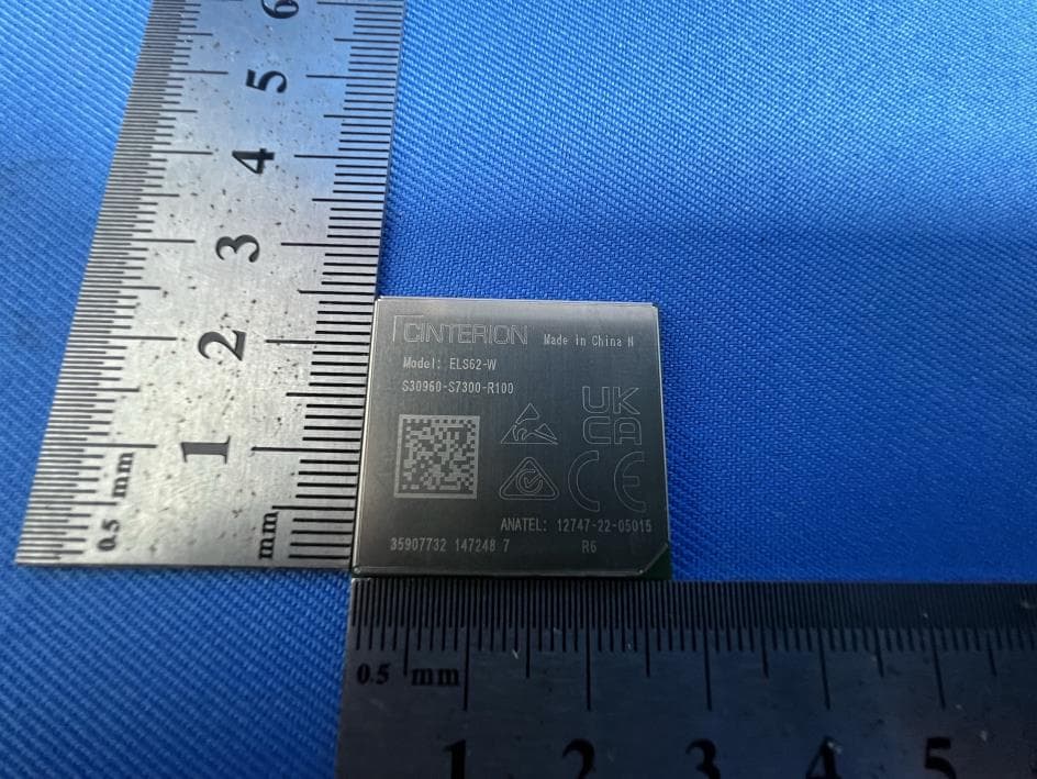
QIPELS62-W
Oct 09, 2023IoT Module
Equipment Class
PCB - PCS Licensed Transmitter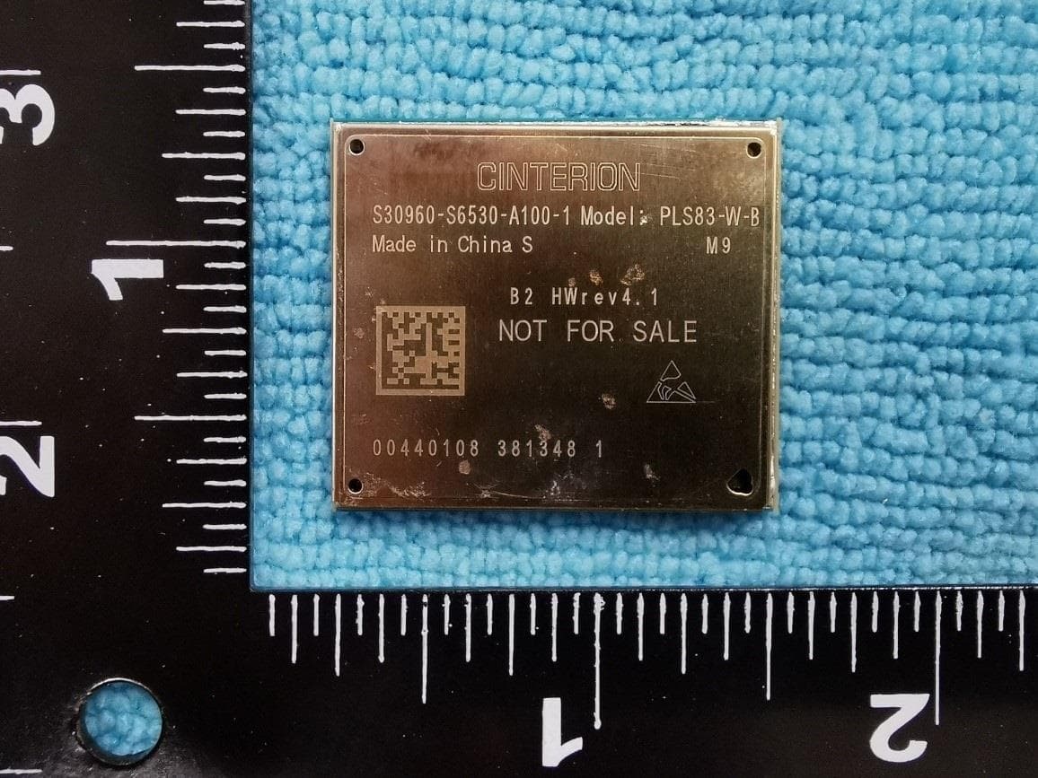
QIPPLS83-W-B
Nov 22, 2022Module
Equipment Class
JBP - Part 15 Class B Computing Device Peripheral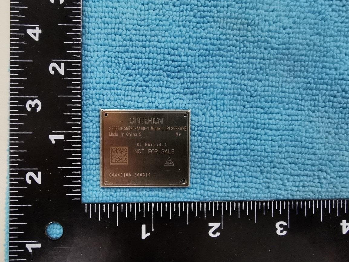
QIPPLS63-W-B
Nov 22, 2022Module
Equipment Class
PCB - PCS Licensed Transmitter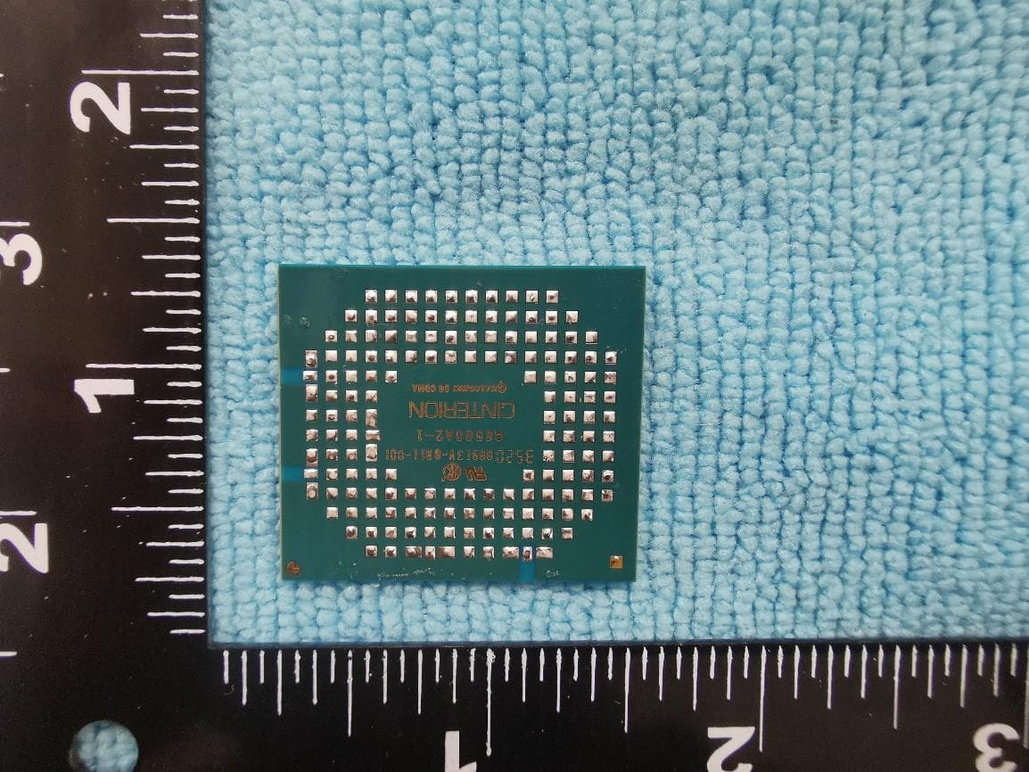
QIPPLS63-X-B
Nov 10, 2022Module
Equipment Class
PCB - PCS Licensed Transmitter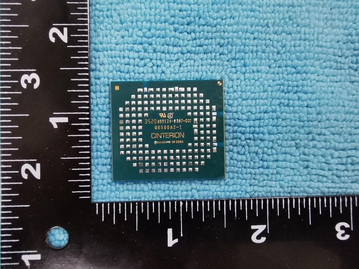
QIPPLS83-X-B
Nov 06, 2022Module
Equipment Class
JBP - Part 15 Class B Computing Device Peripheral