QIPMC45Transmitter Module for mobile applications
Telit Cinterion Deutschland GmbH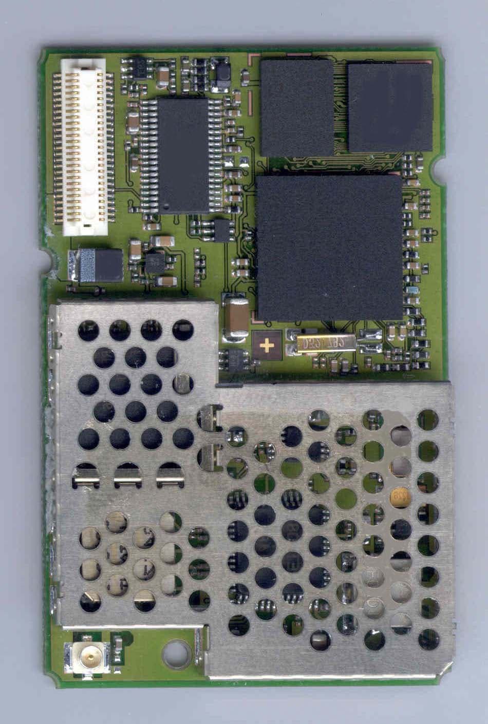
Click to zoom
Application Details
- Equipment Class
- PCB - PCS Licensed Transmitter
- Date of Grant
- Sep 12, 2002
- Application Purpose
- Original Equipment
- Date of Application
- Sep 12, 2002
- Equipment Note
- Transmitter Module for mobile applications
- Frequency Range
- 1850.20000000 - 1909.80000000
- Country
- Germany
Documents & Files
Document Text
Text extracted from the exhibit documents filed with the FCC. Open a document above to read the original.
Users Manual
Siemens Cellular Engine Hardware Interface Description Version 00.02 DocID: MC45_HD_01_V00.02a MC45 Hardware Interface Description P R E L I M I N A R Y MC45_HD_01_V00.02a Page 2 of 90 12.08.2002 Document Name: MC45 Hardware Interface Description Version: 00.02 Date: August 12, 2002 DocId: MC45_HD_01_V00.02a Status: PRELIMINARY General notes With respect to any damages arising in connection with the described product or this document, Siemens shall be liable according to the General Conditions on which the delivery of the described product and this document are based. This product is not intended for use in life support appliances, devices or systems where a malfunction of the product can reasonably be expected to result in personal injury. Siemens AG customers using or selling this product for use in such applications do so at their own risk and agree to fully indemnify Siemens for any damages resulting from illegal use or resale. Applications incorporating the described product must be designed to be in accordance with the technical specifications provided in these guidelines. Failure to comply with any of the required procedures can result in malfunctions or serious discrepancies in results. Furthermore, all safety instructions regarding the use of mobile technical systems, including GSM products, which also apply to cellular phones must be followed. Handheld applications such as mobile phones or PDAs incorporating the described product must be in accordance with the guidelines for human exposure to radio frequency energy. The Specific Absorption Rate (SAR) of the application must be evaluated and approved to be compliant with national and international safety standards or directives. Subject to change without notice at any time. Copyright notice Copying of this document and giving it to others and the use or communication of the contents thereof, are forbidden without express authority. Offenders are liable to the payment of damages. All rights reserved in the event of grant of a patent or the registration of a utility model or design. Copyright © Siemens AG 2002 MC45 Hardware Interface Description P R E L I M I N A R Y MC45_HD_01_V00.02a Page 3 of 90 12.08.2002 Contents 0 Version History........................................................................................................... 7 1 Introduction ................................................................................................................ 9 1.1 Related documents ............................................................................................. 9 1.2 Terms and abbreviations....................................................................................10 1.3 Type approval ....................................................................................................13 1.4 Safety precautions .............................................................................................15 2 Product concept........................................................................................................17 2.1 MC45 key features at a glance...........................................................................18 2.2 Circuit concept ...................................................................................................21 3 Application Interface.................................................................................................22 3.1 Operating modes...............................................................................................23 3.2 Power supply.....................................................................................................25 3.2.1 Power supply pins on the board-to-board connector.............................25 3.2.2 Minimizing power losses.......................................................................26 3.2.3 Charging control ...................................................................................27 3.2.3.1 Battery pack characteristics ......................................................28 3.2.3.2 Recommended battery pack .....................................................29 3.2.3.3 Implemented charging technique ..............................................30 3.2.3.4 Operating modes during charging .............................................31 3.2.3.5 Charger requirements ...............................................................32 3.3 Power up / down scenarios ................................................................................33 3.3.1 Turn on MC45 ......................................................................................33 3.3.1.1 Turn on MC45 using the ignition line /IGT (Power on)...............33 3.3.1.2 Timing of the ignition process ...................................................34 3.3.1.3 Turn on MC45 using the POWER signal ...................................35 3.3.1.4 Turn on MC45 using the RTC (Alarm mode).............................35 3.3.2 Power saving ........................................................................................36 3.3.2.1 No power saving (AT+CFUN=1)................................................36 3.3.2.2 NON-CYCLIC SLEEP mode (AT+CFUN=0)..............................36 3.3.2.3 CYCLIC SLEEP mode (AT+CFUN=5, 6, 7 and 8).....................36 3.3.2.4 Timing of the /CTS signal in CYCLIC SLEEP modes................37 3.3.2.5 Wake up MC45 from SLEEP mode...........................................39 3.3.3 Turn off MC45 ......................................................................................40 3.3.3.1 Turn off MC45 using AT command ...........................................40 3.3.3.2 Emergency shutdown using /EMERGOFF pin...........................41 3.3.4 Automatic shutdown .............................................................................42 3.3.4.1 Temperature dependent shutdown............................................42 3.3.4.2 Undervoltage shutdown if battery NTC is present ...................…
Text truncated - open the document above for the full version.
External Photos
Test Report 2-20542043b/02, Page 56 of 65 20542043b_02.doc 7. Photographs 7.1. External photos of EUT Photograph 1: EUT front side with shielding
ID Label/Location Info
ALS BETRIEBSGEHEIMNIS ANVERTRAUT. ALLE RECHTE VORBEHALTEN. PROPRIETARY DATA, COMPANY CONFIDENTAL. ALL RIGHTS RESERVED. REV MESSAGE DATE NAME DATE NAME SIEMENS AG Sheet of 18.03.2001 1 11.04.02 DIS 10457 1 1 Boe Bölcke MC45 Cellular Engine Zulassung / IMEI WM RD HW3 520 Label aus Polymatic mit schwarzer Beschriftung T yp-Approval Code: TAC Strich-Code: Typ 128, Tabelle C und B Besonderheit: Bei der 15stelligen IMEI-Nr. werden die Stellen 1-14 mit der Tabelle C als Barcode generiert. Die Stelle 15 wird mit der Tabelle B gedruckt. 5) 7) 6) sechsstellige laufende Seriennummer = Strich-Code (Klartext) Vorgabe durch PICS Aktuelle Zuteilung: 000 0011-9 9 Final Assembly Code: 41 FAC 15. Stelle, Klartext CHECK DIGIT XXXXXX FF SSSSSS C 9999 xxx xxx 1) Z30880-Z9999-Z27-* Schild: 4) S30880-S8300-A100-1 0682 MC45 1) Produktname Font D1.1 2) Sachnummer Font A2.2 Höhe 1,2 mm 3) Datumscode Font: A2.2 nach IEC 62 4) CE-Kennung Höhe 5mm nach BABT-Dokument 556 26/93 5) US/Canda Zulassungs Kennzeichnung Höhe ? mm 6) Barcode IMEI-Nummer Code 128 Größe 1 Ratio 2 Höhe 3mm 7) Klarschrift IMEI-nummer: Font: A 3.3 8) US/Canda Zulassungsnummer Font A2.2 Höhe 1,2 mm 2) 3) YY 2 19.04.02 Boe 558 FCC ID:QIPMC45 MC45 IC: 267W-MC45 8)
Internal Photos
Test Report 2-20542043b/02, Page 57 of 65 20542043b_02.doc 7.2. Internal photos of EUT Photograph 2: EUT front side without shielding Test Report 2-20542043b/02, Page 58 of 65 20542043b_02.doc Photograph 3: EUT rear side
RF Exposure Info
Application QIPMC45 Dipl.-Ing. Karin Silberhorn CETECOM GmbH, Essen, Germany Prediction of MPE limit at given distance Equation from page 18 of OET Bulletin 65, Edition 97-01 2 4R PG S π = where: S = power density P = power input to the antenna G = power gain of the antenna in the direction of interest relative to an isotropic radiator R = distance to the center of radiation of the antenna The table below is excerpted from Table 1B of 47 CFR 1.1310 titled Limits for Maximum Permissible Exposure (MPE), Limits for General Population/Uncontrolled Exposure: Frequency Range (MHz) Power Density (mW/cm 2 ) Averaging Time (minutes) 300 – 1500 f/1500 30 1500 – 100.000 1.0 30 where f = frequency in MHz Prediction Antenna Type: 0dBi Antenna / 3dBi Antenna / 6 dBi Antenna / 7 dBi Antenna Maximum peak output power at antenna input terminal: 29.7 dBm Maximum peak output power at antenna input terminal: 933,254 mW Antenna gain(typical): 0 dBi Maximum antenna gain: 1 numeric Prediction distance: 20 cm Prediction frequency: 1880 MHz MPE limit for uncontrolled exposure at prediction frequency: 1 2 cm mW Power density at prediction frequency: with Antenna Gain of 0dBi 0,1857 2 cm mW Power density at prediction frequency: with Antenna Gain of 3dBi 0,3713 2 cm mW Power density at prediction frequency: with Antenna Gain of 6dBi 0,7427 2 cm mW Power density at prediction frequency: with Antenna Gain of 7dBi 0,9305 2 cm mW Maximum allowable antenna gain: 7,3137 dBi This predictions demonstrate the following: 1) The power density levels at a distance of 20 cm with typical antennas of 0-7dBi are below the maximum levels allowed by the FCC regulations. 2) The antenna gain where 1 2 cm mW would be reached at 20 cm distance, is G= 7,3137dBi
Test Report
Note: The test results relate only to the individual items which have been tested. This report shall not be reproduced in parts without the written approval of the testing laboratory Applicant:Siemens AG CETECOM - Certification and Testing in Communications GmbH Im Teelbruch 122 D-45219 Essen Germany Telephone: + 49 (0) 20 54 / 95 19 0 Fax: + 49 (0) 2054 / 95 19 20 T E S T R E P O R T No.: 2-20542043b/02 for GPRS/GSM 900/1800/1900 Module MC 45 + DSB 45 + Votronic Handset FCC ID: QIPMC45 TTI-P-G081/94 FCC Registration No. 99538 Test Report 2-20542043b/02, Page 2 of 65 20542043b_02.doc Table of contents 1. SUMMARY OF TEST RESULTS3 2. ADMINISTRATIVE DATA4 2.1. I DENTIFICATION OF THE TESTING LABORATORY 4 2.2. T EST LOCATION 4 2.3. O RGANIZATIONAL ITEMS 4 2.4. A PPLICANT ́ S DETAILS 4 2.5. M ANUFACTURER ́ S DETAILS 4 3. EQUIPMENT UNDER TEST (EUT)5 3.1. EUT: T YPE , S/N ETC . AND SHORT DESCRIPTIONS USED IN THIS TEST REPORT 5 3.2. A UXILIARY E QUIPMENT (AE): T YPE , S/N ETC . AND SHORT DESCRIPTIONS 5 3.3. EUT SET - UPS 6 3.4. EUT OPERATING MODES 6 4. TEST SET-UPS7 4.1. T EST S ET - UP 1 FOR C ONDUCTED MEASUREMENTS 7 4.2. T EST S ET - UP 2 FOR R ADIATED MEASUREMENTS 8 4.3. P ARAMETER SETTINGS ON MOBILE PHONE AND CMU9 5. MEASUREMENTS10 5.1. C ALIBRATION OF ANECHOIC CHAMBER 10 5.2. RF POWER OUTPUT § 2.1046 CONDUCTED 11 5.3. RF POWER OUTPUT § 2.1046 RADIATED 12 5.4. O CCUPIED BANDWIDTH § 2.104913 5.5. S PURIOUS EMISSIONS AT ANTENNA TERMINALS § 2.105117 5.6. F IELD STRENGTH OF SPURIOUS RADIATION § 2.105326 5.7. F REQUENCY STABILITY / TEMPERATURE VARIATION § 2.105550 6. INSTRUMENTS AND ANCILLARY EQUIPMENT „CTC“53 6.1. S INGLE INSTRUMENTS 53 6.2. T EST SYSTEMS 55 7. PHOTOGRAPHS56 7.1. E XTERNAL PHOTOS OF EUT56 7.2. I NTERNAL PHOTOS OF EUT57 7.3. P HOTOS OF TEST SET - UP 59 Test Report 2-20542043b/02, Page 4 of 65 20542043b_02.doc 2. Administrative Data 2.1. Identification of the testing laboratory Company name:CETECOM Certification and Testing in Communications GmbH Address:Im Teelbruch 122 D-45219 Essen - Kettwig Germany Laboratory accreditation:DAR-Registration No.: TTI-P-G081/94 FCC- Registration No.: 99538 Responsible for testing laboratory:Dipl.-Ing. W. Richter Deputies:Dieter Franke Dipl.-Ing. Karin Silberhorn Dipl.-Ing. Heiko Strehlow 2.2. Test location 2.2.1. Test laboratory “CTC” Company name:see chapter 2.1. Identification of the testing laboratory 2.3. Organizational items Reference No.:20542043 Order No.:-- Responsible for test report and project leader:Dipl.-Ing. V. Krueger Receipt of EUT:2002-07-17 Date(s) of test:2002-07-17 – 2002-08-01 Date of report:2002-08-19 Number of report pages:65 Number of diagram pages (annex):no diagrams --------------------------------------------------------------------------------------------------------------------------------------- Version of template: 4.05 2.4. Applicant ́s details Applicant ́s name:Siemens AG Address:Siemensdamm 50 13629 Berlin Germany Contact person:Mr. Hussein Halawi; Tel. +49 30 38630211 2.5. Manufacturer ́s details Manufacturer ́s name:please see Applicant ́s details Address:please see Applicant ́s details Test Report 2-20542043b/02, Page 5 of 65 20542043b_02.doc 3. Equipment under test (EUT) 3.1. EUT: Type, S/N etc. and short descriptions used in this test report short descrip- tion*) EUTType S/N serial number HW hardware status SW software status EUT A GPRS / GSM ModuleMC 4500499941137807 7 B 2.5SW: 34 EUT B Development support box DSB 45# 200B 1.1V 1.0 EUT C Handset VotronicHH-SI-30.3Sample 2V 1.1-- EUT D EUT E EUT F *) EUT short description is used to simplify the identification of the EUT in this test report. Additional Information for EUT A Frequency range:1850.2 – 1909.8 MHz Number of channels:300 Nominal power supply voltage:4,5 V (of module) Power supply range:3,3 – 4,5 V Temperature range:-30°C - +60°C Emission designator:300KGXW Antenna: integral antenna: antenna connector: external antenna Max. stated nominal output power: conducted 30,0 ±2 dBm, radiated 30,0 ±2 dBm EIRP Max. measured output power:conducted 29,7 dBm, radiated 30,6 dBm EIRP 3.2. Auxiliary Equipment (AE): Type, S/N etc. and short descriptions AE short descrip- tion*) Auxiliary EquipmentType S/N serial number HW Hardware status SW software status AE 1 RS 232 cable 1for Com1 - Port--Length=1.81 meter-- AE 2 RS 232 cable 2for Com2 - Port--Length=1.81 meter-- AE 3 AC/DC AdapterMW 1000 GSSample 2Input: 230 V AC, 50 Hz, 28 W Output: 3-6V 9-12 V DC, 1000 mA, 12 VA -- AE 4 GSM Antenna900/ 1800 MHz# 10 dB Gain length=1 meter -- *) AE short description is used to simplify the identification of the auxiliary equipment in this test report. Test Report 2-20542043b/02, Page 6 of 65 20542043b_02.doc 3.3. EUT set-ups EUT set-up no.*) Combination of EUT and AERemarks set. 1EUT A + EUT B + EUT C + AE 1 + AE 2 + AE 3 Set-up for conducted measurements: MC 45 situated outside the DSB45 support-box com-1 cable and com-2 cable connected to DSB-Box but not terminated on the other side (open) set. 2EUT A + EUT B + EUT C + AE 1 + AE 2 + AE 3 + AE 4 Set-up for radiated measurements: MC 45 situated outside the DSB45 support-box com-1 cable and com-2 cable connected to DSB-Box but not terminated on the other side (open) set. 3---- *) EUT set-up no. is used to simplify the identification of the EUT set-up in this test report. 3.4. EUT operating modes EUT operating mode no.*) Description of operating modes Additional information op. 1 IDLE The mobile station is synchronized at the Broadcast Control Channel (BCCH) and listening to the Common Control Channel (CCCH), for details please see chapter: 4.3. Parameter settings on mobile phone and CMU. op. 2 TCH A communication link is established between the mobile station and the test simulator. The transmitter is operated at its maximum rated output power, for details please see chapter: 4.3. Parameter settings on mobile phone and CMU. *) EUT operating mode no. is used to simplify the test report. Test Report 2-20542043b/02, Page 7 of 65 20…
Text truncated - open the document above for the full version.
Test Setup Photos
Test Report 2-20542043b/02, Page 59 of 65 20542043b_02.doc 7.3. Photos of test set-up Photograph 4: Test setup for radiated emissions Test Report 2-20542043b/02, Page 60 of 65 20542043b_02.doc Photograph 5: Test setup for radiated emissions Test Report 2-20542043b/02, Page 61 of 65 20542043b_02.doc Photograph 6: Test site for f > 1 GHz Test Report 2-20542043b/02, Page 62 of 65 20542043b_02.doc Photograph 7: Test site for conducted measurements (1) Test Report 2-20542043b/02, Page 63 of 65 20542043b_02.doc Photograph 8: Test site for conducted measurements (2) Test Report 2-20542043b/02, Page 64 of 65 20542043b_02.doc Photograph 9: Test site for temperature variations (1) Test Report 2-20542043b/02, Page 65 of 65 20542043b_02.doc Photograph 10: Test site for temperature variations (2)
Contact Information
Applicant
Leandro Wan-Dall(Head of Certification Management)
Test Firm
CETECOM GmbHWolfgang Richter
Technical Specifications
| # | Rule Parts | Frequency Range | Power Output | Emission | Tolerance |
|---|---|---|---|---|---|
| 1 | 24E | 1.85 GHz - 1.91 GHz | 933.00 mW | 300KGXW | 0.0300000000 ppm |
Other Applications from Telit Cinterion Deutschland GmbH
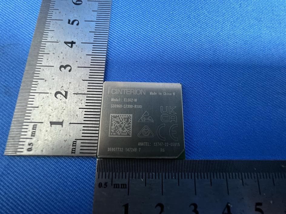
QIPELS62-W
Oct 09, 2023IoT Module
Equipment Class
PCB - PCS Licensed Transmitter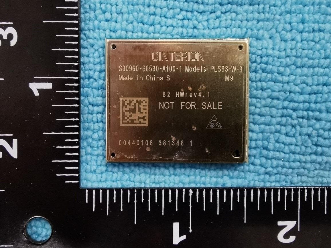
QIPPLS83-W-B
Nov 22, 2022Module
Equipment Class
JBP - Part 15 Class B Computing Device Peripheral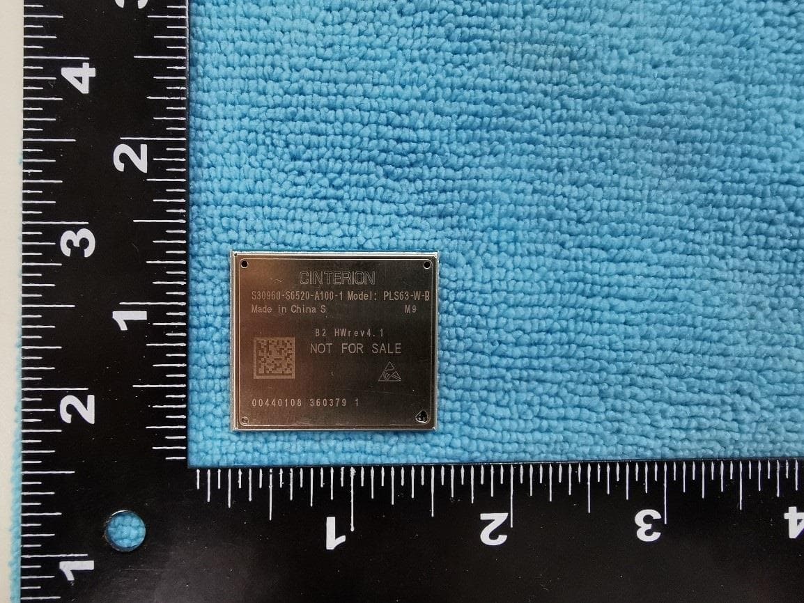
QIPPLS63-W-B
Nov 22, 2022Module
Equipment Class
PCB - PCS Licensed Transmitter
QIPPLS63-X-B
Nov 10, 2022Module
Equipment Class
PCB - PCS Licensed Transmitter
QIPPLS83-X-B
Nov 06, 2022Module
Equipment Class
JBP - Part 15 Class B Computing Device Peripheral