QIPMC55IQuadband GSM/GPRS Module
Telit Cinterion Deutschland GmbH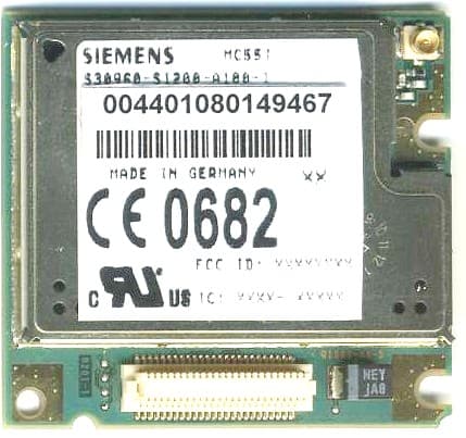
Click to zoom
Application Details
- Equipment Class
- PCB - PCS Licensed Transmitter
- Date of Grant
- Jan 22, 2008
- Application Purpose
- Original Equipment
- Date of Application
- Jan 21, 2008
- Equipment Note
- Quadband GSM/GPRS Module
- Frequency Range
- 1850.20000000 - 1909.80000000
- Country
- Germany
Documents & Files
Document Text
Text extracted from the exhibit documents filed with the FCC. Open a document above to read the original.
External Photos
Siemens Cellular Engine MC55i Siemens Cellular Engine MC55i Top side Siemens Cellular Engine MC55i Bottom Side
ID Label/Location Info
Siemens Cellular Engine MC55i MC55i Label
Internal Photos
Siemens Cellular Engine MC55i Siemens Cellular Engine MC55i Top side without shielding Siemens Cellular Engine MC55i Bottom Side
RF Exposure Info
The test results relate only to the individual items which have been tested. This report shall not be reproduced in parts without the written approval of the testing laboratory © Copyright ■ All rights reserved by CETECOM Applicant: Siemens AG Laboratory Accreditation and Listings DAT-P-176/94-02 Federal Communications Commission FCC Registration No. 99538 MRA US-EU DE0003 Industry Canada IC Registration No. IC 3465 accredited according to DIN EN ISO/IEC 17025 CETECOM GmbH Laboratory RC & EMC Im Teelbruch 116 D-45219 Essen Germany Telephone: + 49 (0) 20 54 / 95 19-954 Fax: + 49 (0) 20 54 / 95 19-964 for GSM/GPRS Module MC55i FCC Part 2.1091 & RSS-102, Issue 2 T E S T R E P O R T RF-Exposure Mobile Device (MPE) No.: 2-20722858d/07-C1 EMC Test Report 2-20722858d/07-C1, Page 2 of 20 B_2_20722858d_07-C1.doc Table of contents 1. SUMMARY OF TEST RESULTS 3 1.1. TESTS OVERVIEW 3 2. ADMINISTRATIVE DATA 4 2.1. Identification of the testing laboratory 4 2.2. Test location 4 2.3. Organizational items 4 2.4. Applicant’s details 4 2.5. Manufacturer’s details 4 3. EQUIPMENT UNDER TEST (EUT) 5 3.1. Additional declaration and description of main EUT 5 3.2. EUT: Type, S/N etc. and short descriptions used in this test report 5 3.3. Auxiliary Equipment (AE): Type, S/N etc. and short descriptions 6 3.4. EUT set-ups 6 3.5. EUT operating modes 7 3.6. Additional declaration and description of EUT’s 8 3.7. Configuration of cables used for testing 8 4. MEASUREMENTS SET-UPS 9 4.1. Conducted measurements test set-up 9 4.2. Parameter Settings on mobile phone and base station CMU200 10 5. RADIO FREQUENCY EXPOSURE EVALUATION: MOBILE EQUIPMENT 11 6. MEASUREMENT UNCERTAINTIES 14 7. INSTRUMENTS AND ANCILLARY 15 7.1. Used equipment “CTC” 15 8. PHOTOGRAPHS 19 9. ANNEX 1: DIAGRAMS OF THE MEASUREMENTS 19 10. ANNEX 2: RF-TECHNICAL BRIEF COVER SHEET ACCORDING RSS-102, ISSUE 2. 19 EMC Test Report 2-20722858d/07-C1, Page 4 of 20 B_2_20722858d_07-C1.doc 2. Administrative Data 2.1. Identification of the testing laboratory Company name: CETECOM GmbH Address: Im Teelbruch 116 45219 Essen – Kettwig, Germany Laboratory accreditations/Listings: DAR-Registration No. DAT-P-176/94-02 FCC-Registration No. 99538 MRA US-EU DE0003 IC-Registration No. 3465 Responsible for testing laboratory: Dipl.-Ing. W. Richter Deputies: Dipl.-Ing. H. Strehlow, D. Franke 2.2. Test location 2.2.1. Test laboratory “CTC” Company name: see chapter 2.1. Identification of the testing laboratory . 2.3. Organizational items Order No.: 20722858 Responsible for test report and project leader: Dipl.-Ing. C. Lorenz Receipt of EUT: 20.11.2007 Date(s) of test: 21.11.2007 – 07.12.2007 Date of report: 04.01.2008 Number of report pages: 20 --------------------------------------------------------------------------------------------------------------------------------------- Version of template: 07.11 2.4. Applicant’s details Applicant’s name: Siemens AG Address: ICM WM RD ST3 Siemensdamm 50 13623 Berlin Germany Contact person: Mr. Thorsten Liebig 2.5. Manufacturer’s details Manufacturer’s name: please see Applicant's details Address: please see Applicant's details EMC Test Report 2-20722858d/07-C1, Page 5 of 20 B_2_20722858d_07-C1.doc 3. Equipment under test (EUT) 3.1. Additional declaration and description of main EUT Main function GSM/GPRS Module Type MC55i GSM Frequency range GSM850: 824 - 849MHz (Uplink), 869 – 894 MHz (Downlink) GSM1900: 1850-1910MHz (Uplink), 1930-1990MHz (Downlink) Type of modulation GMSK Number of channels GSM850: 128 – 251, 125 channels GSM1900: 512 – 810, 300 channels EMISSION DESIGNATOR(S) Antenna Type Antenna connector, tested with external standard car magnet antenna MAX PEAK Output Power: GSM 850 Radiated GSM 1900 32.02 dBm 30.82 dBm MAX PEAK Output Power: GSM 850 Conducted GSM1900 32.57 dBm 30.11 dBm FCC-ID QIPMC55i IC 267W-MC55i Installed option -- Special EMI components -- EUT sample type Production : Pre-Production Engineering (Applicant's declaration, = not selected, : = selected) 3.2. EUT: Type, S/N etc. and short descriptions used in this test report Short descrip- tion*) EUT Type S/N serial number HW hardware status SW software status EUT A GSM/GPRS Module MC55i IMEI: 004401080149 475 B2.1 00.303 EUT B GSM/GPRS Module MC55i IMEI: 004401080149 509 B2.1 00.303 *) EUT short description is used to simplify the identification of the EUT in this test report. EMC Test Report 2-20722858d/07-C1, Page 6 of 20 B_2_20722858d_07-C1.doc 3.3. Auxiliary Equipment (AE): Type, S/N etc. and short descriptions AE short descrip- tion *) Auxiliary Equipment Type S/N serial number HW hardware status SW software status AE 1 DSB Board DSB45_B1.1 S30880- Q8301-A1-3 A5B009001034 50-A B1.1 -- AE 2 DSB Board DSB45_B1.1 S30880- Q8301-A1-3 A5B009001034 50-B B1.1 -- AE 3 Handset for Siemens M20T, MC35T, TC35T, DSB35 017953211304 HH-SI- 30.3/V1.1/0-- -- AE 4 GSM Antenna 1140.26-MMCX/m -- -- -- AE 5 RS 232 cable -- -- -- -- AE 6 Notebook Dell D610 EMC #4 -- Windows XP + Terminal Program *) AE short description is used to simplify the identification of the auxiliary equipment in this test report. 3.4.EUT set-ups EUT set-up no.*) Combination of EUT and AE Remarks Set. 1 EUT A + AE 1 + AE 3 + (AE 4) + AE 5 + (AE 6) For conducted tests no AE 4 used *) EUT set-up no. is used to simplify the identification of the EUT set-up in this test report. EMC Test Report 2-20722858d/07-C1, Page 7 of 20 B_2_20722858d_07-C1.doc 3.5. EUT operating modes EUT operating mode no.*) Description of operating modes Additional information op. 1 GSM 850 Idle mode BCCH 50 The mobile station is synchronized to the Broadcast Control Channel (BCCH) and listening to the Common Control Channel (CCCH). Periodic location update is disabled. op. 2 GSM 850 TCH mode A communication link is established between the mobile station and the test simulator. The transmitter is operated at its maximum rated output power: 33 dBm (power class 4; power control level 5). The input signal to the receiver is modulated…
Text truncated - open the document above for the full version.
Test Report
The test results relate only to the individual items which have been tested. This report shall not be reproduced in parts without the written approval of the testing laboratory © Copyright ■ All rights reserved by CETECOM Applicant: Siemens AG Laboratory Accreditation and Listings DAT-P-176/94-02 Federal Communications Commission FCC Registration No. 99538 MRA US-EU DE0003 Industry Canada IC Registration No. IC 3465 accredited according to DIN EN ISO/IEC 17025 CETECOM GmbH Laboratory RC & EMC Im Teelbruch 116 D-45219 Essen Germany Telephone: + 49 (0) 20 54 / 95 19-954 Fax: + 49 (0) 20 54 / 95 19-964 for GSM/GPRS Module MC55i FCC Part 22/24 & RSS 132, Issue 2 RSS 133, Issue 3 T E S T R E P O R T No.: 2-20722858c/07-C1 EMC Test Report 2-20722858c/07-C1, Page 2 of 139 B_2_20722858c_07-C1.doc Table of contents 1. SUMMARY OF TEST RESULTS 3 1.1. TESTS OVERVIEW 3 2. ADMINISTRATIVE DATA 5 2.1. Identification of the testing laboratory 5 2.2. Test location 5 2.3. Organizational items 5 2.4. Applicant’s details 5 2.5. Manufacturer’s details 5 3. EQUIPMENT UNDER TEST (EUT) 6 3.1. Additional declaration and description of main EUT 6 3.2. EUT: Type, S/N etc. and short descriptions used in this test report 6 3.3. Auxiliary Equipment (AE): Type, S/N etc. and short descriptions 7 3.4. EUT set-ups 7 3.5. EUT operating modes 8 3.6. Additional declaration and description of EUT’s 9 3.7. Configuration of cables used for testing 9 4. MEASUREMENTS SET-UPS 10 4.1. Conducted measurements test set-up 10 4.2. Radiated measurements test set-up 11 4.3. Parameter Settings on mobile phone and base station CMU200 12 5. MEASUREMENTS AND TEST RESULTS 13 5.1. RF power output (Conducted and Radiated) 13 5.2. Occupied 99% bandwidth 16 5.3. Emission limits radiated (Spurious emission radiated) f< 30 MHz 18 5.4. Emission limits (Spurious emission) f> 30 MHz 20 5.5. Frequency stability on temperature and voltage variations 28 6. MEASUREMENT UNCERTAINTIES 37 7. CALIBRATION METHOD OF ANECHOIC CHAMBER 38 8. INSTRUMENTS AND ANCILLARY 39 8.1. Used equipment “CTC” 39 9. ANNEX 1: DIAGRAMS OF THE MEASUREMENTS 43 9.1. EMISSION BANDWIDTH 43 9.2. OCCUPIED 99% BANDWIDTH 49 9.3. SPURIOUS EMISSIONS CONDUCTED 55 9.4. RADIATED SPURIOUS EMISSIONS 81 9.5. MAGNETIC FIELD STRENGTH MEASUREMENTS (RADIATED) 131 9.6. IC : CONDUCTED MEASUREMENTS IN RX-MODE 850MHZ, RSS-132-ISSUE 2, CHAPTER 4.6 137 9.7. IC: CONDUCTED MEASUREMENTS IN RX-MODE 1900 MODE: RSS-133-ISSUE 3, CHAPTER 6.7(B) 138 10. ANNEX A - PHOTOS: EUT AND ACCESSORIES 139 11. ANNEX B - PHOTOS: TEST SET-UP 139 EMC Test Report 2-20722858c/07-C1, Page 3 of 139 B_2_20722858c_07-C1.doc 1. Summary of test results The test results apply exclusively to the test samples as presented in chapter 3.1. The CETECOM GmbH does not assume responsibility for any conclusions and generalisations taken in conjunction with other specimens or samples of the type of the item presented to tests. The presented GSM 850/900/1800/1900 Module can be build inside host applications and extends their capability by wireless GSM technology. Data transmission or voice application are possible field applications. In order to verify the compliance, a representative configuration consisting of different auxiliary equipment was chosen. Embedded in this configuration, the GSM/GPRS Module can be tested. Following tests have been performed to show compliance with applicable standards: FCC Part 2, Part 22 and Part 24, Subpart E (Broadband PCS) of the FCC CFR 47 Rules and RSS-132 and RS- 133 IC rules. ATTESTATION: I declare that all measurements were performed by me or under my supervision and that all measurements have been performed and are correct to my best knowledge and belief to Industry Canada standards. All requirements as shown in below table are met in accordance with enumerated standards. 1.1. TESTS OVERVIEW TEST CASES PORT REFERENCES & LIMITS EUT set-up EUT opera- Result FCC StandardRSS Section TEST LIMIT ting mode TX-Mode RF POWER (conducted) Antenna terminal (conducted) §2.1046 -- N/A 1 2+4 Passed RF-POWER radiated (ERP/EIRP) Cabinet §2.1046 §22.913(a)(2) §24.232(c) RSS-132: 4.4 SRSP-503: 5.1.3 RSS-133:6.4 SRSP-510: 5.1.2 < 7 Watt ERP < 2 Watt (EIRP) 1 2+4 Passed SPURIOUS EMISSIONS (conducted) Antenna terminal (conducted) §2.1051 §22.917(a)(b) §24.238(a)(b) RSS 132: 4.5.1 RSS 133: 6.5.1 43+10log(P) dBc 1 2+4 Passed 99% OCCUPIED BANDWIDTH Antenna terminal (conducted) §2.202 §2.1049 §22.917(a) §24.238(a) RSS Gen:4.6.1 99% Power 1 2+4 Passed EMC Test Report 2-20722858c/07-C1, Page 5 of 139 B_2_20722858c_07-C1.doc 2. Administrative Data 2.1. Identification of the testing laboratory Company name: CETECOM GmbH Address: Im Teelbruch 116 45219 Essen – Kettwig, Germany Laboratory accreditations/Listings: DAR-Registration No. DAT-P-176/94-02 FCC-Registration No. 99538 MRA US-EU DE0003 IC-Registration No. 3465 Responsible for testing laboratory: Dipl.-Ing. W. Richter Deputies: Dipl.-Ing. H. Strehlow, D. Franke 2.2. Test location 2.2.1. Test laboratory “CTC” Company name: see chapter 2.1. Identification of the testing laboratory . 2.3. Organizational items Order No.: 20722858 Responsible for test report and project leader: Dipl.-Ing. C. Lorenz Receipt of EUT: 20.11.2007 Date(s) of test: 21.11.2007 – 07.12.2007 Date of report: 03.01.2008 Number of report pages: 139 --------------------------------------------------------------------------------------------------------------------------------------- Version of template: 07.11 2.4. Applicant’s details Applicant’s name: Siemens AG Address: ICM WM RD ST3 Siemensdamm 50 13623 Berlin Germany Contact person: Mr. Thorsten Liebig 2.5. Manufacturer’s details Manufacturer’s name: please see Applicant's details Address: please see Applicant's details EMC Test Report 2-20722858c/07-C1, Page 6 of 139 B_2_20722858c_07-C1.doc 3. Equipment under test (EUT) 3.1. Additional declaration and description of main EUT Main function GSM/GPRS Module Type MC55i GSM Frequency range GSM850: 824 - 849MHz (Uplink), 8…
Text truncated - open the document above for the full version.
Test Report
The test results relate only to the individual items which have been tested. This report shall not be reproduced in parts without the written approval of the testing laboratory © Copyright ■ All rights reserved by CETECOM Applicant: Siemens AG Laboratory Accreditation and Listings DAT-P-176/94-02 Federal Communications Commission FCC Registration No. 99538 MRA US-EU DE0003 Industry Canada IC Registration No. IC 3465 accredited according to DIN EN ISO/IEC 17025 CETECOM GmbH Laboratory RC & EMC Im Teelbruch 116 D-45219 Essen Germany Telephone: + 49 (0) 20 54 / 95 19-954 Fax: + 49 (0) 20 54 / 95 19-964 FCC Part 15, Subpart B T E S T R E P O R T No.: 2-20722858b/07-C1 for GSM/GPRS Module MC55i EMC Test Report 2-20722858b/07-C1, Page 2 of 30 B_2_20722858b_07-C1.doc Table of contents 1. SUMMARY OF TEST RESULTS 3 1.1. Emission (EMI) 3 2. ADMINISTRATIVE DATA 4 2.1. Identification of the testing laboratory 4 2.2. Test location 4 2.3. Organizational items 4 2.4. Applicant’s details 4 2.5. Manufacturer’s details 4 3. EQUIPMENT UNDER TEST (EUT) 5 3.1. Additional declaration and description of main EUT 5 3.2. EUT: Type, S/N etc. and short descriptions used in this test report 5 3.3. Auxiliary Equipment (AE): Type, S/N etc. and short descriptions 6 3.4. EUT set-ups 6 3.5. EUT operating modes 6 3.6. Additional declaration and description of EUT 7 3.7. Configuration of cables used for testing 7 4. MEASUREMENTS 8 4.1. AC-Power lines conducted emissions 8 4.2. Radiated emissions, Part 15.109 Unintentional Radiators 9 5. MEASUREMENT UNCERTAINTIES 13 6. INSTRUMENTS AND ANCILLARY 14 6.1. Used equipment “CTC” 14 7. ANNEX 1: DIAGRAMS OF THE MEASUREMENTS 18 7.1. Radiated Field Strength accord. §15.109: IDLE 1900 Mode 18 7.2. Radiated Field Strength accord. §15.109: IDLE 850 Mode 24 8. ANNEX A - PHOTOS: EUT AND ACCESSORIES 30 9. ANNEX B - PHOTOS: TEST SET-UP 30 EMC Test Report 2-20722858b/07-C1, Page 4 of 30 B_2_20722858b_07-C1.doc 2. Administrative Data 2.1. Identification of the testing laboratory Company name: CETECOM GmbH Address: Im Teelbruch 116 45219 Essen – Kettwig, Germany Laboratory accreditations/Listings: DAR-Registration No. DAT-P-176/94-02 FCC-Registration No. 99538 MRA accreditation US-EU DE0003 Responsible for testing laboratory: Dipl.-Ing. W. Richter Deputies: Dipl.-Ing. H. Strehlow, D. Franke 2.2. Test location 2.2.1. Test laboratory “CTC” Company name: see chapter 2.1. Identification of the testing laboratory . 2.3. Organizational items Order No.: 20722858 Responsible for test report and project leader: Dipl.-Ing. C. Lorenz Receipt of EUT: 20.11.2007 Date(s) of test: 21.11.2007, 23.11.2007 Date of report: 03.01.2008 Number of report pages: 30 --------------------------------------------------------------------------------------------------------------------------------------- Version of template: 07.11 2.4. Applicant’s details Applicant’s name: Siemens AG Address: ICM WM RD ST3 Siemensdamm 50 13623 Berlin Germany Contact person: Mr. Thorsten Liebig 2.5. Manufacturer’s details Manufacturer’s name: please see Applicant's details Address: please see Applicant's details EMC Test Report 2-20722858b/07-C1, Page 5 of 30 B_2_20722858b_07-C1.doc 3. Equipment under test (EUT) 3.1. Additional declaration and description of main EUT Main function GSM/ GPRS Module Type MC55i GSM Frequency range GSM850: 824 - 849MHz (Uplink), 869 – 894 MHz (Downlink) GSM1900: 1850-1910MHz (Uplink), 1930-1990MHz (Downlink) Type of modulation GMSK Number of channels GSM850: 128 – 251, 125 channels GSM1900: 512 – 810, 300 channels EMISSION DESIGNATOR(S) GSM850: 245K19GXW GSM1900: 246K79GXW Antenna Type Antenna connector, tested with external standard car magnet antenna MAX PEAK Output Power: GSM 850 Radiated GSM 1900 32.02 dBm, Remark 1 30.82 dBm, Remark 1 MAX PEAK Output Power: GSM 850 Conducted GSM1900 --, see test report 2-20722858c/07 --, see test report 2-20722858c/07 FCC-ID QIPMC55i Installed option -- EUT sample type Production : Pre-Production Engineering (Applicant's declaration, = not selected, : = selected) Remark 1.) only valid with applicants supplied GSM antenna, AE 3 3.2. EUT: Type, S/N etc. and short descriptions used in this test report Short descrip- tion*) EUT Type S/N serial number HW hardware status SW software status EUT A GSM/GPRS Module MC55i IMEI: 004401080149 475 B2.1 00.303 *) EUT short description is used to simplify the identification of the EUT in this test report. EMC Test Report 2-20722858b/07-C1, Page 6 of 30 B_2_20722858b_07-C1.doc 3.3. Auxiliary Equipment (AE): Type, S/N etc. and short descriptions AE short descrip- tion *) Auxiliary Equipment Type S/N serial number HW hardware status SW software status AE 1 DSB Box 45 DSB45_B1.1 S30880- Q8301-A1-3 A5B009001034 50 B1.1 -- AE 2 Votronic Handset M20T, MC35T, TC35T, DSB35 017953211304 HH-SI- 30.3/V1.1/0-- -- AE 3 GSM Antenna 1140.26-MMCX/m -- -- -- AE 4 RS 232 cable -- -- -- -- AE 5 Notebook Dell D610 EMC #4 -- Windows XP + Terminal Program *) AE short description is used to simplify the identification of the auxiliary equipment in this test report. 3.4.EUT set-ups EUT set-up no.*) Combination of EUT and AE Remarks Set. 1 EUT A + AE 1 + AE 2 + AE 3 + AE 4 + (AE 5) After setting up the right operating mode the notebook (AE5) is disconnected from the DSB Box45. The call is maintained. *) EUT set-up no. is used to simplify the identification of the EUT set-up in this test report. 3.5. EUT operating modes EUT operating mode no.*) Description of operating modes Additional information Op. 1 GSM 850 Idle mode BCCH 182 The mobile station is synchronized to the Broadcast Control Channel (BCCH) and listening to the Common Control Channel (CCCH). Op. 3 GSM 1900 Idle mode BCCH 651 The mobile station is synchronized to the Broadcast Control Channel (BCCH) and listening to the Common Control Channel (CCCH). *) EUT operating mode no. is used to simplify the test report. EMC Test Report 2-20722858b/07-C1, Page 7 of 30 B_2_20722858b_07-C1.doc 3.6. Addition…
Text truncated - open the document above for the full version.
Contact Information
Applicant
Paolo Schiratti(VP Global Certification)
Technical Contact
Technical Specifications
| # | Rule Parts | Frequency Range | Power Output | Emission | Tolerance |
|---|---|---|---|---|---|
| 2 | 24E | 1.85 GHz - 1.91 GHz | 1.026 W | 300KGXW | 0.0024 ppm |
Other Applications from Telit Cinterion Deutschland GmbH
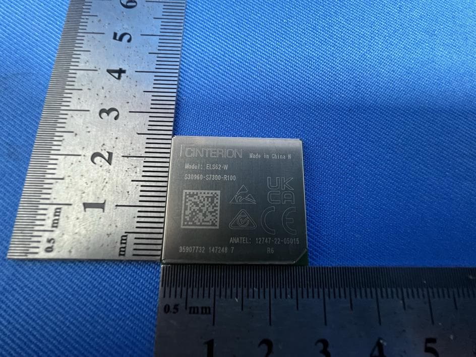
QIPELS62-W
Oct 09, 2023IoT Module
Equipment Class
PCB - PCS Licensed Transmitter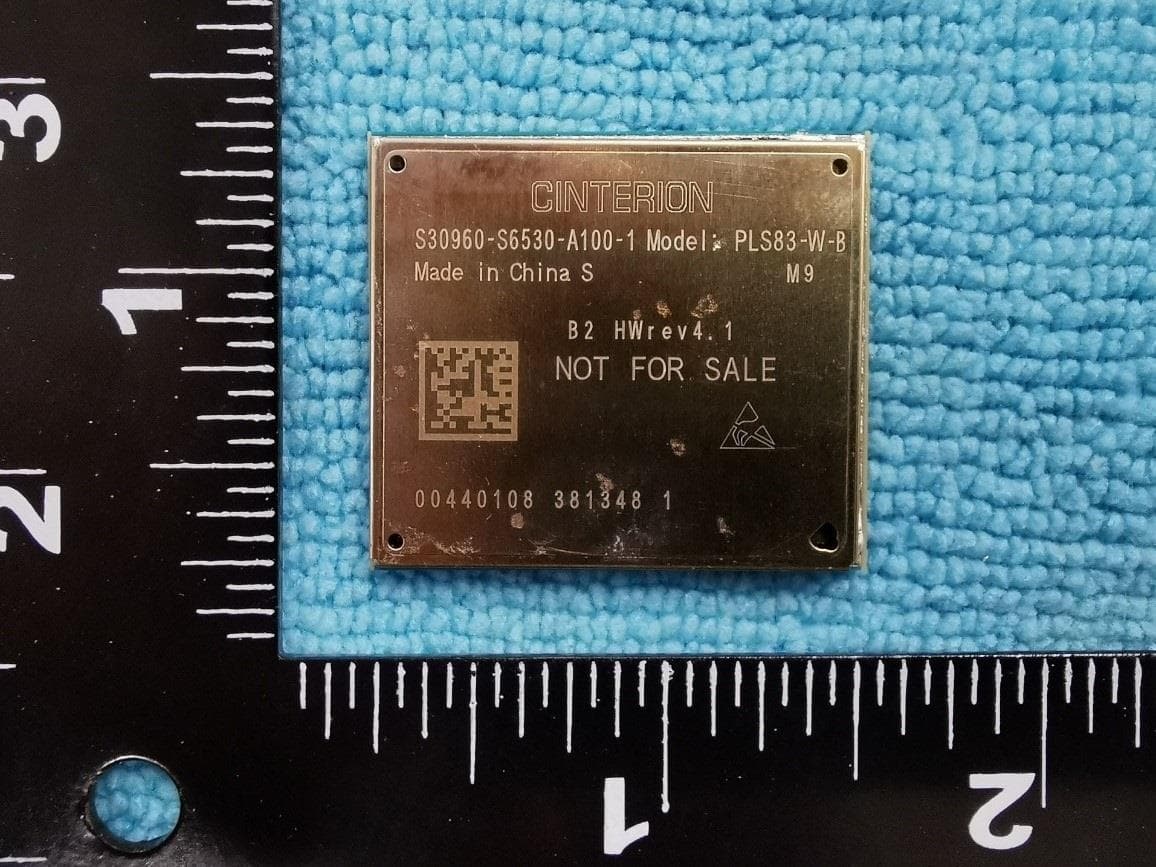
QIPPLS83-W-B
Nov 22, 2022Module
Equipment Class
JBP - Part 15 Class B Computing Device Peripheral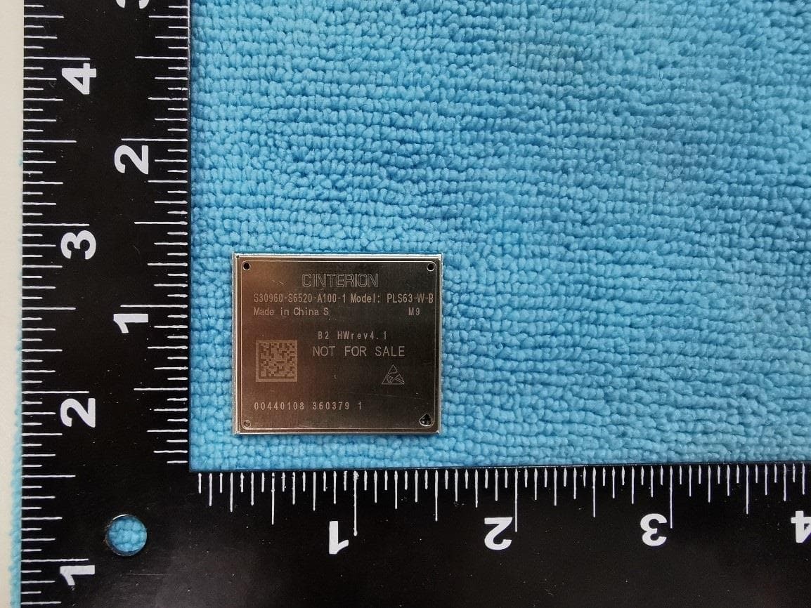
QIPPLS63-W-B
Nov 22, 2022Module
Equipment Class
PCB - PCS Licensed Transmitter
QIPPLS63-X-B
Nov 10, 2022Module
Equipment Class
PCB - PCS Licensed Transmitter
QIPPLS83-X-B
Nov 06, 2022Module
Equipment Class
JBP - Part 15 Class B Computing Device Peripheral