QJ5-CFRG-BT01Bluetooth Adapter
J&M Corporation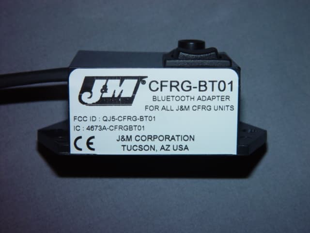
Click to zoom
Application Details
- Equipment Class
- DSS - Part 15 Spread Spectrum Transmitter
- Date of Grant
- Oct 10, 2006
- Application Purpose
- Original Equipment
- Date of Application
- Oct 10, 2006
- Equipment Note
- Bluetooth Adapter
- Frequency Range
- 2402.00000000 - 2480.00000000
- Company
- J&M Corporation
- Country
- United States
Documents & Files
Document Text
Text extracted from the exhibit documents filed with the FCC. Open a document above to read the original.
Users Manual
# CFRG-BT01 Bluetooth ® Adapter For J&M CFRG Units Installation and Operation Instructions © 2006 J&M Corporation. All rights reserved. 6/06 Universal Cellular Telephone/GPS/Radar Detector Audio Integration Terminal Cell Phone GPS right-angle plug to the GPS audio output (GPS not included) CFRG-Module black 2-pin plug black 2-pin plug black wire—ground connection black wire—ground connection red wire—power connection for radar detector red wire—power connection for GPS driver's helmet headset (not included) 5-pin din red 6-pin plug cell phone rocker control switch factory-installed headset lead white 3-pin plug black 3-pin plug Radar Detector black 2-pin plug 5-pin headset lead from stock audio system 5-pin din fuse holder ground to frame—black wire 12v swithable —red wire volume multifunction button red 4-pin plug CFRG-BT01 Diagram A Thank you for the confidence you have shown by purchasing one of J&M’s innovative products. If you have any questions during the installation, or require further assistance, you may call us at 1-800-358-0881 from 8:00 a.m. to 5:00 p.m. Mountain Standard Time, Monday through Friday. Tucson, Arizona U.S.A. Tel (800) 358-0881 Website: http://www.jmcorp.com E-mail: [email protected] Installation 1. Mount the CFRG-BT01 where desired, taking into consideration the wire lengths going to the CFRG unit to allow easy access to the control buttons. 2. Connect the 4-pin red plug from the CFRG-BT01 to the 4-pin red plug on the CFRG unit. 3. Connect the black 2-pin plugs in series between the CFRG unit and the radar detector. (See Diagram A) Operation 1. Turn on the motorcycle ignition and then depress and hold the multifunction button located on the top of the CFRG-BT01 until the blue LED stops flashing then release the button. 2. Now depress and hold the button on the CFRG-BT01 for 10 seconds. The LED should now be flashing rapidly to indicate pair- ing mode. 3. Enable the Bluetooth mode on your cell phone and perform a device discovery from the phone. (Refer to your cell phone’s user guide) 4. Select the J & M Cell/Nav from the list of devices. 5. When prompted by the phone, enter passkey 0000 and confirm to pair your cell phone to the CFRG-BT01. 6. The CFRG-BT01 is paired with your phone when the LED goes from rapidly flashing to a slower flash. 7. The multifunction switch allows you to answer incoming cell phone calls (if not in auto answer mode), voice command dialing feature along with pairing the CFRG-BT01 to a Bluetooth enabled cell phone or Bluetooth enabled navigation device. 8. To answer an incoming call briefly depress the multifunction button (if not in auto answer mode) and switch the on/off rocker control switch from the CFRG to the on position. 9. To activate the voice command dialing function of the phone — “turn on”, the on/off rocker switch from the CFRG and briefly depress the multifunction button on the CFRG-BT01. 10. Once enabled and linked, the CFRG-BT01 will turn off and on automatically with the motorcycle ignition switch. Noise and Interference Motorcycle audio systems by their very nature are noisy. While we do not guarantee this system to be completely free from electrical noises and interference, we have taken many steps to achieve that goal: the power supply system is well filtered, the unit is shielded in its metal container, and the cables associated with the unit are shielded. Power requirements: 11-16 volts DC negative ground Minimum speaker impedance: 32 Typical current draw: 1.5 amps Changes or modifications not expressly approved by the party responsible for compliance could void the user’s authority to operate the equipment. FCC Regulations This device complies with 15 of the FCC Rules. Operation is sub- ject to the following two conditions: (1) This device may not cause harmful interference, and (2) this device must accept any interference received, including interference that may cause undesired operation. Industry Canada Notice to Users Operation is subject to the following two conditions: (1) This device may not cause interference and (2) This device must accept any interference, including interference that may cause undesired operation of the device Ref IC RSS 210 Sec. 5.11. The term”IC:” before the certification/registration number only signifies that registration was performed based on a Declaration of Conformity indicating that Industry Canada technical specifica- tions were met. It does not imply that Industry Canada approved the equipment.
Cover Letter(s)
1415SouthCherryAvenue Tucson,Arizona85713-1997 TEL:520-624-7000 FAX:520-624-6202 E-M:[email protected] WEB:www.jmcorp.com DATE09-27-2006 EquipmentAutorisationDivision FederalCommunicationsCommission 7435OaklandMillsRoad Columbia,MD21046 FCC10:QJ5-CFRG-BT01 ProductName:CFRG-BT01 RequestforConfidentialitv PursuanttoSections0.457and0.459ofthecommissionsrules,weherebyrequestthat thefollowingdocumentsbeheldconfidential: •Schematic •Blockdiagram •PartsList •OperationalDescription Thesematerialscontaintradesecretsandproprietaryinformationandarenot customarilyreleasedtothepublic.Thepublicdisclosureofthisinformationmightbe harmfultothecompanyandprovideunjustifiedbenefitstoourcompetitors. Dated this 27 Day ofSeptember 2006 By: B~~ /'Sig·ture JimVertz Printed Title:Director ofR&D Onbehalf of:J&MCorporation Telephone:1-520-624-7000
External Photos
External Photos
ID Label/Location Info
2" 1"
ID Label/Location Info
Label Location
Internal Photos
Internal Photos
RF Exposure Info
The maximum output power is below the low threshold for SAR testing. Peak eirp is 2.1 mW Low threshold is 60/2.4 = 25 mW
Test Report
Nemko Test Report: 6L0434RUS1 rev 1 Applicant: J & M Corp. 1415 South Cherry Ave Tucson AZ 85746 Equipment Under Test: CFRG-BT01 In Accordance With: FCC Part 15, Subpart C, 15.247 Frequency Hopping Transmitters Tested By: Nemko USA Inc. 802 N. Kealy Lewisville, Texas 75057-3136 TESTED BY: DATE: September 28,2006 Kevin Rose, Wireless Engineer APPROVED BY: DATE: September 28,2006 David Light, Senior Wireless Engineer Total number of pages: 35 FCC PART 15, SUBPART C FREQUENCY HOPPING SPREAD SPECTRUM TRANSMITTER Nemko USA, Inc EQUIPMENT: CFRG-BT01 PROJECT NO. 6L0434RUS1 rev1: Page 2 of 35 Table of Contents Section 1. Summary of Test Results ....................................................... 3 Section 2. Equipment Under Test (E.U.T.) .............................................. 5 Section 3. Channel Separation ................................................................ 7 Section 4. Time of Occupancy............................................................... 10 Section 5. Peak Power Output .............................................................. 17 Section 6. Spurious Emissions (Antenna Conducted) ............................ 19 Section 7. Spurious Emissions (Radiated) ............................................. 21 Section8. Test Equipment List .............................................................. 24 ANNEX A - TEST DETAILS ..................................................................... 25 ANNEX B - TEST DIAGRAMS ................................................................. 33 FCC PART 15, SUBPART C FREQUENCY HOPPING SPREAD SPECTRUM TRANSMITTER Nemko USA, Inc EQUIPMENT: CFRG-BT01 PROJECT NO. 6L0434RUS1 rev1: Page 3 of 35 Section 1. Summary of Test Results Manufacturer: J & M Corporation Name: CFRG-BT01 Model Number: CFRG-BT01 Serial Number: None General: All measurements are traceable to national standards. These tests were conducted on a sample of the equipment for the purpose of demonstrating compliance with Part 15, Subpart C, Paragraph 15.247 for Frequency Hopping Spread Spectrum devices. Radiated tests were conducted is accordance with ANSI C63.4-2003. Radiated emissions are made on an open area test site. A description of the test facility is on file with the FCC. New Submission Production Unit Class II Permissive Change Pre-Production Unit THIS TEST REPORT RELATES ONLY TO THE ITEM(S) TESTED. THE FOLLOWING DEVIATIONS FROM, ADDITIONS TO, OR EXCLUSIONS FROM THE TEST SPECIFICATIONS HAVE BEEN MADE. See “ Summary of Test Data”. Nemko USA Inc. authorizes the above named company to reproduce this report provided it is reproduced in its entirety and for use by the company’s employees only. Any use which a third party makes of this report, or any reliance on or decisions to be made based on it, are the responsibility of such third parties. Nemko USA Inc. accepts no responsibility for damages, if any, suffered by any third party as a result of decisions made or actions based on this report. This report applies only to the items tested. FCC PART 15, SUBPART C FREQUENCY HOPPING SPREAD SPECTRUM TRANSMITTER Nemko USA, Inc EQUIPMENT: CFRG-BT01 PROJECT NO. 6L0434RUS1 rev1: Page 4 of 35 Summary of Test Data NAME OF TEST PARA. NO. RESULT Powerline Conducted Emissions 15.207(a) N/A Channel Separation 15.247(a)(1) Complies Time of Occupancy 15.247(a)(1)(ii) Complies 20 dB Occupied Bandwidth 15.247(a)(1) Not defined Peak Power Output 15.247(b) Complies Spurious Emissions (Antenna Conducted) 15.247(c) N/A Spurious Emissions (Radiated) 15.247(c) Complies Footnotes: N/A (The EUT has a integral antenna.) The EUT has a 9VDC battery EUT was tested with a new battery FCC PART 15, SUBPART C FREQUENCY HOPPING SPREAD SPECTRUM TRANSMITTER Nemko USA, Inc EQUIPMENT: CFRG-BT01 PROJECT NO. 6L0434RUS1 rev1: Page 5 of 35 Section 2. Equipment Under Test (E.U.T.) General Equipment Information Frequency Band: 902 – 928 MHz 2400 – 2483.5 MHz Channel Frequencies: 2402 to 2480 MHz Number of Channels: 79 Channel Spacing: 1MHz User Frequency Adjustment: Software controlled FCC PART 15, SUBPART C FREQUENCY HOPPING SPREAD SPECTRUM TRANSMITTER Nemko USA, Inc EQUIPMENT: CFRG-BT01 PROJECT NO. 6L0434RUS1 rev1: Page 6 of 35 Description of DUT The CFRG-BT01 allows the end user to connect Bluetooth devices such as cellular telephones to J&M Corporations CFRG Units System Diagram The EUT is a stand-alone device. FCC PART 15, SUBPART C FREQUENCY HOPPING SPREAD SPECTRUM TRANSMITTER Nemko USA, Inc EQUIPMENT: CFRG-BT01 PROJECT NO. 6L0434RUS1 rev1: Page 7 of 35 Section 3. Channel Separation NAME OF TEST: Channel Separation PARA. NO.: 15.247(a)(1) TESTED BY: Kevin Rose DATE: August 29, 2006 Test Results: Complies. Measurement Data: See 20 dB BW plot Measured 20 dB bandwidth: 840 kHz Channel Separation: 1MHz Equipment Used: 1464 1081 802 Measurement Uncertainty: +/- 1.7 dB Temperature: 20°C Relative Humidity: 46% FCC PART 15, SUBPART C FREQUENCY HOPPING SPREAD SPECTRUM TRANSMITTER Nemko USA, Inc EQUIPMENT: CFRG-BT01 PROJECT NO. 6L0434RUS1 rev1: Page 8 of 35 Number of hopping channels = 79 FCC PART 15, SUBPART C FREQUENCY HOPPING SPREAD SPECTRUM TRANSMITTER Nemko USA, Inc EQUIPMENT: CFRG-BT01 PROJECT NO. 6L0434RUS1 rev1: Page 9 of 35 Channel separation FCC PART 15, SUBPART C FREQUENCY HOPPING SPREAD SPECTRUM TRANSMITTER Nemko USA, Inc EQUIPMENT: CFRG-BT01 PROJECT NO. 6L0434RUS1 rev1: Page 10 of 35 Section 4. Time of Occupancy NAME OF TEST: Time of Occupancy PARA. NO.: 15.247(a)(1)(iii) TESTED BY: Kevin Rose DATE: August 29, 2006 Test Results: Complies. Measurement Data: Maximum Dwell Time On Any Channel: 158 mS/31.6 seconds Equipment Used: 1659-802-1980 FCC PART 15, SUBPART C FREQUENCY HOPPING SPREAD SPECTRUM TRANSMITTER Nemko USA, Inc EQUIPMENT: CFRG-BT01 PROJECT NO. 6L0434RUS1 rev1: Page 11 of 35 Pulse width One second graph FCC PART 15, SUBPART C FREQUENCY HOPPING SPREAD SPECTRUM TRANSMITTER Nemko USA, Inc EQUIPMENT: CFRG-BT01 PROJECT NO. 6L0434RUS1 rev1: Page 12 of 35 31.6 second graph FCC PART 15, SUBPART…
Text truncated - open the document above for the full version.
Contact Information
Applicant
John J Lazzeroni(President)
Technical Contact
Non-Technical Contact
Nemko USAChristine Taylor
[email protected]972 436 9600
Test Firm
Nemko USA, Inc.Tom Tidwell
Technical Specifications
| # | Rule Parts | Frequency Range | Power Output |
|---|---|---|---|
| 1 | 15C | 2.40 GHz - 2.48 GHz | 1.58 mW |
Other Applications from J&M Corporation

QJ5JMHS-WLS465
Mar 19, 2013Motorcycle Helmet Bluetooth Intercom Headset
Equipment Class
DSS - Part 15 Spread Spectrum Transmitter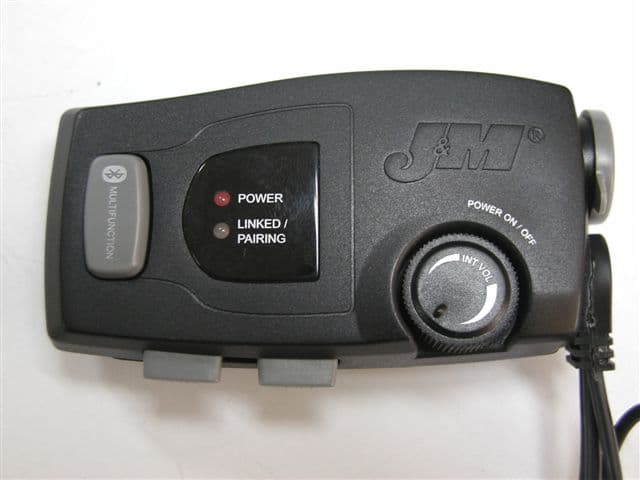
QJ5-HS-BLU
May 28, 2007Bluetooth Device
Equipment Class
DSS - Part 15 Spread Spectrum Transmitter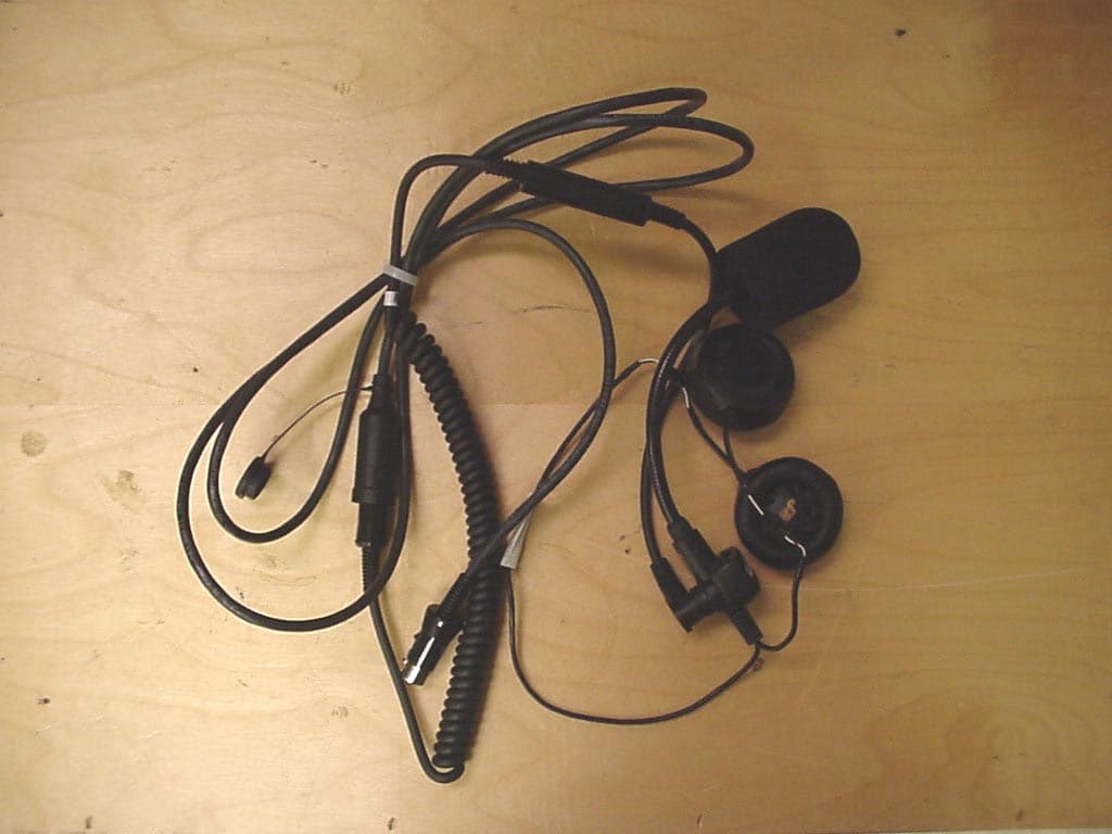
QJ5-JMCB-2003
Aug 27, 2003Motorcycle Mount Mobile CB Transceiver
Equipment Class
TNB - Licensed Non-Broadcast Station Transmitter