QJ5-JMCB-2003Motorcycle Mount Mobile CB Transceiver
J&M Corporation
Click to zoom
Application Details
- Equipment Class
- TNB - Licensed Non-Broadcast Station Transmitter
- Date of Grant
- Aug 27, 2003
- Application Purpose
- Original Equipment
- Date of Application
- Aug 27, 2003
- Equipment Note
- Motorcycle Mount Mobile CB Transceiver
- Frequency Range
- 26.96500000 - 27.40500000
- Company
- J&M Corporation
- Country
- United States
Documents & Files
Document Text
Text extracted from the exhibit documents filed with the FCC. Open a document above to read the original.
Users Manual
Rhein Tech Laboratories Client: J & M Corp. 360 Herndon Parkway Model: JMCB-2003 Suite 1400 Standards: FCC Part 95/IC RSS-136 Herndon, VA 20170 Report Number: 2003126 http://www.rheintech.com Date: August 21, 2003 45 of 63 APPENDIX I: MANUAL Please refer to the following pages. Quality Motorcycle Audio JMCB-2003 Handlebar-mounted 40 Channel Citizen’s Band Transceiver (CB)/ Weather Radio with Rider-Passenger Intercom and Auxiliary Audio Input Owner’s Manual © COPYRIGHT 2003 J&M CORPORATION. ALL RIGHTS RESERVED Table of Contents Product DescriptionSection 1. FCC RegulationsSection 2. Performance FeaturesSection 3. Package ContentsSection 4. Controls and FunctionsSection 5. Installation InstructionsSection 6. Operation InstructionsSection 7. Antenna InformationSection 8. CB Channel Frequency ChartSection 9. SpecificationsSection 10. Warranty StatementSection 11. 2. FCC Regulations You do not need an FCC license to operate this radio in the United States. However, you must know and be familiar with Part 95 of the FCC Rules in regard to Subpart D of the Citizen’s Band Radio Ser vice, a copy of which is enclosed in the JMCB-2003 packaging. 1. Product Description The JMCB-2003 is a compact Citizen’s Band radio designed to operate in the 26.965 MHz to 27.405 MHz band. This lightweight unit also features rider-to-passenger intercom, an auxiliar y audio input for an audio source such as an MP-3 player, and ten weather channels, consisting of seven NOAA frequencies and three international marine frequencies. 3. Performance Features •Maximum legal RF output Power (4W) with high-level modulation (in accordance with FCC Part 95 rules). •Radio receives current National Weather Ser vice broadcasts on one or more of seven separate frequencies and periodic marine weather information on three separate frequencies. •Hi/Lo TX Power selection button •Built-in automatic gain control (AGC) •Phase locked loop synthesizer provides clear voice transmission and reception on all CB channels •Integrated rider-passenger intercom •Auxiliar y audio input (stereo) 4. Package Contents •CB unit JMCB-2003 •12V Power harness •Headset connection cables •Auxiliar y audio input cable •Owner’s manual •Copy of FCC Part 95, Subpart D •Copy of NOAA Weather Network frequency list 5 Controls and Functions A. Auxiliary Audio Volume—Controls auxiliar y audio/input volume to the headsets. B. Squelch Control—Allows CB background noise to be eliminated when no signal is present. C. On/Off CB and Intercom Volume Control—In the inward position the knob turns the entire unit on and off and controls the CB volume. In the pulled-out position, the knob controls the intercom volume. D. Push-To-Talk Lever—Activates CB radio transmission mode. E. Hi/Lo Power Selector Button—Controls CB TX power level. F. Channel Up—Selects any one of the 40 channels available on the CB radio. It is also used to select any one of the 10 weather channels in the Weather Mode. G. Channel Down—Selects any one of the 40 channels available on the CB radio. It is also used to select any one of the 10 weather channels in the Weather Mode. H. Mode—Used to select CB channels, weather channels or keypad beep. I. LCD Display—Identifies CB or weather channe, Tx (transmit), Wx (weather mode), and signal/power strength. A. B. C. D. E. F.G.H.I. J. Helmet Headset Plugs—Allows hookup to J&M helmet headsets. K. 12V DC Power Cord—Provides power and ground for the JMCB-2003. L. PL-258 Connector—Antenna connector for a rear-mounted CB antenna. M. 3-Pin Connector—Connects auxiliar y audio input to a Walkman ® -type music device or other type of stereo radio system. N. Auxiliary Audio Cable—Connects to a Walkman ® -type music device. to rear-mounted CB antenna (not included) personal stereo/CD/ MP3/cassette music device (not included) optional passenger CB transmit switch J&M #PCS-485 (not included) automotive-type radio adapter J&M #FGA-290 (not included) black 3-pin plug ground to frame fuse holder inline noise filter 12 volt switchable Left speaker (not included) Right speaker (not included) Fairing mounted radio or booster amp (not included) WHITE WHITE / RED RED RED / WHITE OR black 3-pin plug white 9-pin plug female 6-pin din 6-pin locking din 6-pin din driver's helmet headset (not included) passenger's helmet headset (not included) J. J. K. L. M. N. 6. Installation Instructions 1) Mount the JMCB-2003 to the left handlebar using the mounting bracket kit that is applicable to your specific make and model of motorcycle. (Mounting Bracket Kits are sold separately.) 2) Route the wires from the CB radio down the handlebar. Plug in the white 9-pin plug from the supplied wiring harness. Connect the power wire (red) to a switchable power source or accessor y terminal so that the unit is automatically turned off when the igni- tion is turned off. Connect the black wire to a frame ground (not to the batter y nega- tive). If it becomes necessar y to replace the fuse, use a 5 amp fuse for the red wire. 3) Connect the black 3-pin plug to the auxiliar y audio cable and route the cable to the auxiliar y audio source. 4) Route all other cables where desired and hook them up according to the wiring dia- gram. 5) Secure all wires and cables with the zip ties provided. 7. Operation of the JMCB-2003 1) With a helmet headset connected to the JMCB-2003 turn the ignition switch to the ON position. 2) Rotate the SQUELCH knob on the JMCB-2003 fully clockwise. 3) Adjust the OFF/ON CB volume knob to a comfortable volume level and select the desired CB channel. 4) Rotate the SQUELCH knob counterclockwise until the background noise is removed. 5) Plug in your auxiliar y audio/music device and adjust the AUX VOL control on the JMCB-2003 fully clockwise to maximum volume. Adjust the volume on the auxiliar y audio source to a maximum level just before distortion and then adjust the AUX VOL control on the JMCB-2003 down to comfortable level. Further volume adjustments while riding should be made with the CB mounted…
Text truncated - open the document above for the full version.
Users Manual
Rhein Tech Laboratories Client: J & M Corp. 360 Herndon Parkway Model: JMCB-2003 Suite 1400 Standards: FCC Part 95/IC RSS-136 Herndon, VA 20170 Report Number: 2003126 http://www.rheintech.com Date: August 21, 2003 45 of 63 APPENDIX I: MANUAL Please refer to the following pages. Quality Motorcycle Audio JMCB-2003 Handlebar-mounted 40 Channel Citizen’s Band Transceiver (CB)/ Weather Radio with Rider-Passenger Intercom and Auxiliary Audio Input Owner’s Manual © COPYRIGHT 2003 J&M CORPORATION. ALL RIGHTS RESERVED Table of Contents Product DescriptionSection 1. FCC RegulationsSection 2. Performance FeaturesSection 3. Package ContentsSection 4. Controls and FunctionsSection 5. Installation InstructionsSection 6. Operation InstructionsSection 7. Antenna InformationSection 8. CB Channel Frequency ChartSection 9. SpecificationsSection 10. Warranty StatementSection 11. 2. FCC Regulations You do not need an FCC license to operate this radio in the United States. However, you must know and be familiar with Part 95 of the FCC Rules in regard to Subpart D of the Citizen’s Band Radio Ser vice, a copy of which is enclosed in the JMCB-2003 packaging. Changes or modifications not expressly approved by the party responsible for compliance could void the user's authority to operate the equipment. 1. Product Description The JMCB-2003 is a compact Citizen’s Band radio designed to operate in the 26.965 MHz to 27.405 MHz band. This lightweight unit also features rider-to-passenger intercom, an auxiliar y audio input for an audio source such as an MP-3 player, and ten weather channels, consisting of seven NOAA frequencies and three international marine frequencies. 3. Performance Features •Maximum legal RF output Power (4W) with high-level modulation (in accordance with FCC Part 95 rules). •Radio receives current National Weather Ser vice broadcasts on one or more of seven separate frequencies and periodic marine weather information on three separate frequencies. •Hi/Lo TX Power selection button •Built-in automatic gain control (AGC) •Phase locked loop synthesizer provides clear voice transmission and reception on all CB channels •Integrated rider-passenger intercom •Auxiliar y audio input (stereo) 4. Package Contents •CB unit JMCB-2003 •12V Power harness •Headset connection cables •Auxiliar y audio input cable •Owner’s manual •Copy of FCC Part 95, Subpart D •Copy of NOAA Weather Network frequency list 5 Controls and Functions A. Auxiliary Audio Volume—Controls auxiliar y audio/input volume to the headsets. B. Squelch Control—Allows CB background noise to be eliminated when no signal is present. C. On/Off CB and Intercom Volume Control—In the inward position the knob turns the entire unit on and off and controls the CB volume. In the pulled-out position, the knob controls the intercom volume. D. Push-To-Talk Lever—Activates CB radio transmission mode. E. Hi/Lo Power Selector Button—Controls CB TX power level. F. Channel Up—Selects any one of the 40 channels available on the CB radio. It is also used to select any one of the 10 weather channels in the Weather Mode. G. Channel Down—Selects any one of the 40 channels available on the CB radio. It is also used to select any one of the 10 weather channels in the Weather Mode. H. Mode—Used to select CB channels, weather channels or keypad beep. I. LCD Display—Identifies CB or weather channe, Tx (transmit), Wx (weather mode), and signal/power strength. A. B. C. D. E. F.G.H.I. J. Helmet Headset Plugs—Allows hookup to J&M helmet headsets. K. 12V DC Power Cord—Provides power and ground for the JMCB-2003. L. PL-258 Connector—Antenna connector for a rear-mounted CB antenna. M. 3-Pin Connector—Connects auxiliar y audio input to a Walkman ® -type music device or other type of stereo radio system. N. Auxiliary Audio Cable—Connects to a Walkman ® -type music device. to rear-mounted CB antenna (not included) personal stereo/CD/ MP3/cassette music device (not included) optional passenger CB transmit switch J&M #PCS-485 (not included) automotive-type radio adapter J&M #FGA-290 (not included) black 3-pin plug ground to frame fuse holder inline noise filter 12 volt switchable Left speaker (not included) Right speaker (not included) Fairing mounted radio or booster amp (not included) WHITE WHITE / RED RED RED / WHITE OR black 3-pin plug white 9-pin plug female 6-pin din 6-pin locking din 6-pin din driver's helmet headset (not included) passenger's helmet headset (not included) J. J. K. L. M. N. 6. Installation Instructions 1) Mount the JMCB-2003 to the left handlebar using the mounting bracket kit that is applicable to your specific make and model of motorcycle. (Mounting Bracket Kits are sold separately.) 2) Route the wires from the CB radio down the handlebar. Plug in the white 9-pin plug from the supplied wiring harness. Connect the power wire (red) to a switchable power source or accessor y terminal so that the unit is automatically turned off when the igni- tion is turned off. Connect the black wire to a frame ground (not to the batter y nega- tive). If it becomes necessar y to replace the fuse, use a 5 amp fuse for the red wire. 3) Connect the black 3-pin plug to the auxiliar y audio cable and route the cable to the auxiliar y audio source. 4) Route all other cables where desired and hook them up according to the wiring dia- gram. 5) Secure all wires and cables with the zip ties provided. 7. Operation of the JMCB-2003 1) With a helmet headset connected to the JMCB-2003 turn the ignition switch to the ON position. 2) Rotate the SQUELCH knob on the JMCB-2003 fully clockwise. 3) Adjust the OFF/ON CB volume knob to a comfortable volume level and select the desired CB channel. 4) Rotate the SQUELCH knob counterclockwise until the background noise is removed. 5) Plug in your auxiliar y audio/music device and adjust the AUX VOL control on the JMCB-2003 fully clockwise to maximum volume. Adjust the volume on the auxiliar y audio source to a maximum level just before distortion and then…
Text truncated - open the document above for the full version.
Cover Letter(s)
Rhein Tech Laboratories Client: J & M Corp. 360 Herndon Parkway Model: JMCB-2003 Suite 1400 Standards: FCC Part 95/IC RSS-136 Herndon, VA 20170 Report Number: 2003126 http://www.rheintech.com Date: August 21, 2003 38 of 63 APPENDIX B: AGENCY AUTHORIZATION Please see the following page.
Cover Letter(s)
Rhein Tech Laboratories Client: J & M Corp. 360 Herndon Parkway Model: JMCB-2003 Suite 1400 Standards: FCC Part 95/IC RSS-136 Herndon, VA 20170 Report Number: 2003126 http://www.rheintech.com Date: August 21, 2003 39 of 63 APPENDIX C: CONFIDENTIALITY REQUEST Please see the following page.
External Photos
Rhein Tech Laboratories Client: J & M Corp. 360 Herndon Parkway Model: JMCB-2003 Suite 1400 Standards: FCC Part 95/IC RSS-136 Herndon, VA 20170 Report Number: 2003126 http://www.rheintech.com Date: August 21, 2003 48 of 63 APPENDIX K: EXTERNAL PHOTOGRAPHS PHOTOGRAPH 4: EUT FRONT VIEW PHOTOGRAPH 5: EUT TOP VIEW Rhein Tech Laboratories Client: J & M Corp. 360 Herndon Parkway Model: JMCB-2003 Suite 1400 Standards: FCC Part 95/IC RSS-136 Herndon, VA 20170 Report Number: 2003126 http://www.rheintech.com Date: August 21, 2003 49 of 63 PHOTOGRAPH 6: EUT BOTTOM VIEW Rhein Tech Laboratories Client: J & M Corp. 360 Herndon Parkway Model: JMCB-2003 Suite 1400 Standards: FCC Part 95/IC RSS-136 Herndon, VA 20170 Report Number: 2003126 http://www.rheintech.com Date: August 21, 2003 50 of 63 PHOTOGRAPH 7: EUT RIGHT VIEW Rhein Tech Laboratories Client: J & M Corp. 360 Herndon Parkway Model: JMCB-2003 Suite 1400 Standards: FCC Part 95/IC RSS-136 Herndon, VA 20170 Report Number: 2003126 http://www.rheintech.com Date: August 21, 2003 51 of 63 PHOTOGRAPH 8: EUT LEFT VIEW Rhein Tech Laboratories Client: J & M Corp. 360 Herndon Parkway Model: JMCB-2003 Suite 1400 Standards: FCC Part 95/IC RSS-136 Herndon, VA 20170 Report Number: 2003126 http://www.rheintech.com Date: August 21, 2003 52 of 63 PHOTOGRAPH 9: EUT BACK VIEW Rhein Tech Laboratories Client: J & M Corp. 360 Herndon Parkway Model: JMCB-2003 Suite 1400 Standards: FCC Part 95/IC RSS-136 Herndon, VA 20170 Report Number: 2003126 http://www.rheintech.com Date: August 21, 2003 53 of 63 PHOTOGRAPH 10: EUT WITH ASSOCIATED CABLING Rhein Tech Laboratories Client: J & M Corp. 360 Herndon Parkway Model: JMCB-2003 Suite 1400 Standards: FCC Part 95/IC RSS-136 Herndon, VA 20170 Report Number: 2003126 http://www.rheintech.com Date: August 21, 2003 54 of 63 PHOTOGRAPH 11: HEADSET WITH CABLING Rhein Tech Laboratories Client: J & M Corp. 360 Herndon Parkway Model: JMCB-2003 Suite 1400 Standards: FCC Part 95/IC RSS-136 Herndon, VA 20170 Report Number: 2003126 http://www.rheintech.com Date: August 21, 2003 55 of 63 PHOTOGRAPH 12: SECOND HEADSET WITH CABLING
ID Label/Location Info
Rhein Tech Laboratories Client: J & M Corp. 360 Herndon Parkway Model: JMCB-2003 Suite 1400 Standards: FCC Part 95/IC RSS-136 Herndon, VA 20170 Report Number: 2003126 http://www.rheintech.com Date: August 21, 2003 41 of 63 APPENDIX E: LABEL INFORMATION PHOTOGRAPH 1: FCC ID LABEL SAMPLE AND 2 PART STATEMENT LABEL ON BACK OF EUT
Internal Photos
Rhein Tech Laboratories Client: J & M Corp. 360 Herndon Parkway Model: JMCB-2003 Suite 1400 Standards: FCC Part 95/IC RSS-136 Herndon, VA 20170 Report Number: 2003126 http://www.rheintech.com Date: August 21, 2003 56 of 63 APPENDIX L: INTERNAL PHOTOGRAPHS PHOTOGRAPH 13: BACK SIDE WITH CABLES CONNECTED Rhein Tech Laboratories Client: J & M Corp. 360 Herndon Parkway Model: JMCB-2003 Suite 1400 Standards: FCC Part 95/IC RSS-136 Herndon, VA 20170 Report Number: 2003126 http://www.rheintech.com Date: August 21, 2003 57 of 63 PHOTOGRAPH 14: PCB MOUNTED IN CASE Rhein Tech Laboratories Client: J & M Corp. 360 Herndon Parkway Model: JMCB-2003 Suite 1400 Standards: FCC Part 95/IC RSS-136 Herndon, VA 20170 Report Number: 2003126 http://www.rheintech.com Date: August 21, 2003 58 of 63 PHOTOGRAPH 15: INSIDE FRONT CASE Rhein Tech Laboratories Client: J & M Corp. 360 Herndon Parkway Model: JMCB-2003 Suite 1400 Standards: FCC Part 95/IC RSS-136 Herndon, VA 20170 Report Number: 2003126 http://www.rheintech.com Date: August 21, 2003 59 of 63 PHOTOGRAPH 16: INSIDE BACK CASE Rhein Tech Laboratories Client: J & M Corp. 360 Herndon Parkway Model: JMCB-2003 Suite 1400 Standards: FCC Part 95/IC RSS-136 Herndon, VA 20170 Report Number: 2003126 http://www.rheintech.com Date: August 21, 2003 60 of 63 PHOTOGRAPH 17: BACK WITH SHIELDS Rhein Tech Laboratories Client: J & M Corp. 360 Herndon Parkway Model: JMCB-2003 Suite 1400 Standards: FCC Part 95/IC RSS-136 Herndon, VA 20170 Report Number: 2003126 http://www.rheintech.com Date: August 21, 2003 61 of 63 PHOTOGRAPH 18: BACK WITH SHIELD REMOVED Rhein Tech Laboratories Client: J & M Corp. 360 Herndon Parkway Model: JMCB-2003 Suite 1400 Standards: FCC Part 95/IC RSS-136 Herndon, VA 20170 Report Number: 2003126 http://www.rheintech.com Date: August 21, 2003 62 of 63 PHOTOGRAPH 19: FRONT OF PCB WITH LCD Rhein Tech Laboratories Client: J & M Corp. 360 Herndon Parkway Model: JMCB-2003 Suite 1400 Standards: FCC Part 95/IC RSS-136 Herndon, VA 20170 Report Number: 2003126 http://www.rheintech.com Date: August 21, 2003 63 of 63 PHOTOGRAPH 20: FRONT OF PCB WITH LCD REMOVED
Contact Information
Applicant
John J Lazzeroni(President)
Technical Contact
Rhein Tech LaboratoriesDesmond Fraser
[email protected]703 689 0368
360 Herndon Parkway · Herndon, Virginia · United States
Technical Specifications
| # | Rule Parts | Frequency Range | Power Output | Emission | Tolerance |
|---|---|---|---|---|---|
| 1 | 95D | 26.965 MHz - 27.405 MHz | 2.317 W | 6K00A3E | 0.0050000000 % |
Other Applications from J&M Corporation

QJ5JMHS-WLS465
Mar 19, 2013Motorcycle Helmet Bluetooth Intercom Headset
Equipment Class
DSS - Part 15 Spread Spectrum Transmitter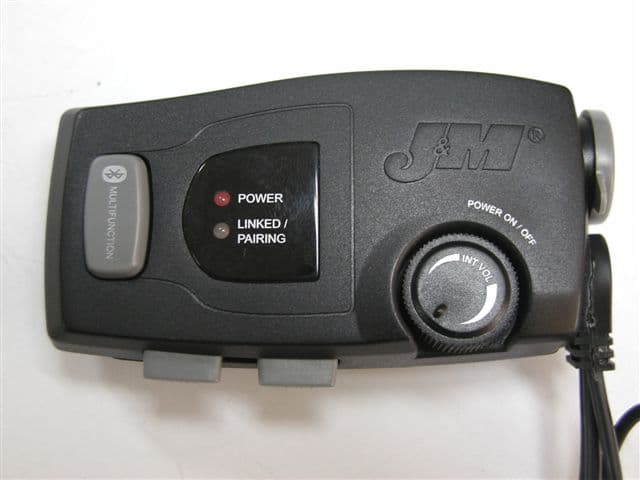
QJ5-HS-BLU
May 28, 2007Bluetooth Device
Equipment Class
DSS - Part 15 Spread Spectrum Transmitter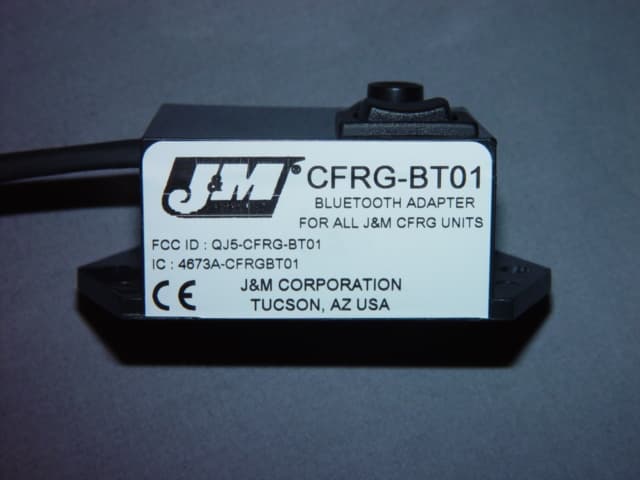
QJ5-CFRG-BT01
Oct 10, 2006Bluetooth Adapter
Equipment Class
DSS - Part 15 Spread Spectrum Transmitter