QJ5-HS-BLUBluetooth Device
J&M Corporation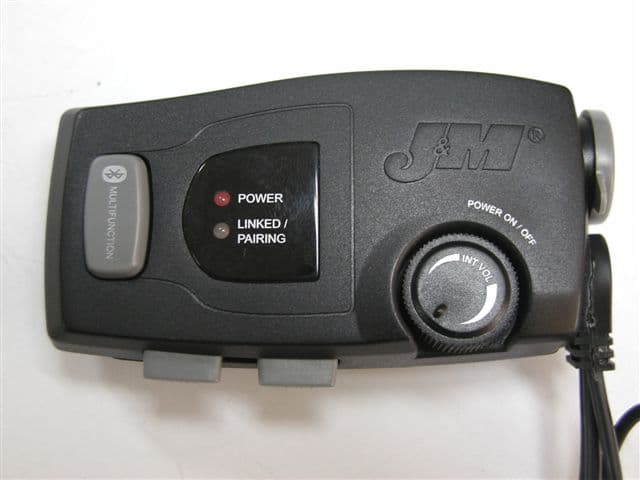
Click to zoom
Application Details
- Equipment Class
- DSS - Part 15 Spread Spectrum Transmitter
- Date of Grant
- May 28, 2007
- Application Purpose
- Original Equipment
- Date of Application
- May 28, 2007
- Equipment Note
- Bluetooth Device
- Frequency Range
- 2402.00000000 - 2480.00000000
- Company
- J&M Corporation
- Country
- United States
Documents & Files
Document Text
Text extracted from the exhibit documents filed with the FCC. Open a document above to read the original.
Users Manual
Bluetooth Helmet Headset #HS-BLU277 Series © 2007 J&M Corporation. All rights reserved. 6/06 Owner’s Manual 1. Product Description The HS-BLU277 is a high audio output, true stereo Bluetooth wireless helmet headset that will link to most Bluetooth enabled audio devices available today. This lightweight unit also features a plug for connecting to passenger’s standard J&M dual mode helmet headset for seamless and simultaneous driver/passen- ger communications. The HS-BLU277 is powered by a recharge- able lithium ion/polymer power cell. 2. Safety and General Information IMPORTANT INFORMATION OF SAFE AND EFFICIENT OPERA- TION. READ THIS INFORMATION BEFORE USING YOUR DEVICE. Users are not permitted to make changes or modify the device in any way. Changes or modifications not expressly approved by the party responsible for compliance could void the user’s authority to operate the equipment. See 47 CFR Sec. 15.21. This device complies with part 15 of the FCC Rules. Operation is subject to the following two conditions: (1) This device may not cause harmful interference, and (2) this device must accept any interference received, including interference that may cause undesired operation. See 47 CFR Sec. 15.19 (3). ELECTROMAGNETIC INTERFERENCE/COMPATIBILITY Note: Nearly every electronic device is suspectible to electro- magnetic interference (EMI) if inadequately shielded, designed or otherwise configured for electromagnetic compatibility. FACILITIES To avoid electromagnetic interference and/or compatibility con- flicts, turn off your device in any facility where posted notices instruct you to do so. Hospitals or health care facilities may be using equipment that is sensitive to external RF energy. AIRCRAFT When instructed to do so, turn off your device when on board an aircraft. Any use of a device must be in accordance with applica- ble regulations per airline crew instructions. MEDICAL DEVICES HEARING AIDS Some devices may interfere with some hearing aids. In the event of such interference, you may want to consult with your hearing aid manufacturer to discuss alternatives. OTHER MEDICAL DEVICES If you use any other personal medical device, consult the manu- facturer of the device to determine if it is adequately shielded from RF energy. Your physician may be able to assist you in obtaining this information. Industry Canada Notice to Users Operation is subject to the following two conditions: (1) This device may not cause interference and (2) This device must accept any interference, including interference that may cause undesired operation of the device. FCC Notice to Users This equipment has been tested and found to comply with the limits for a Class B digital device, pursuant to part 15 of the FCC Rules. These limits are designed to provide reasonable pro- tection against harmful interference in a residential installation. This equipment generates, uses and can radiate radio frequency energy and, if not installed and used in accordance with the instructions, may cause harmful interference to radio communi- cations. However, there is no guarantee that interference will not occur in a particular installation. If this equipment does cause harmful interference to radio or television reception, which can be determined by turning the equipment off and on, the user is encouraged to try to correct the interference by one or more of the following measures: • Reorient or relocate the receiving antenna. • Increase the separation between the equipment and the receiver. • Connect the equipment to an outlet on a circuit different from that to which the receiver is connected. • Consult the dealer or an experienced radio/TV technician for help. 3. Performance Features •High Audio Output •True Two Channel Stereo •Integrated Rider-Passenger Intercom •Separate Bluetooth and Intercom Volume Controls •HSP (Headset Profile) •HFP (Handsfree Profile) •A2DP (Advanced Audio Distribution Profile ((Streaming Stereo)) •AVRCP (Audio Video Remote Control Profile) 4. Package Contents • HS-BLU277 Head Unit • Lithium Ion/Polymer Power Cell • AC Battery Charger • Two Speakers • Microphone • Clamp Assembly • Velcro • Owner’s Manual Product DescriptionSection 1 Safety & General InformationSection 2 Performance FeaturesSection 3 Package ContentsSection 4 Controls and FunctionsSection 5 Installation Instructions For Section 6A Full Coverage & Flip Front Style Helmets Installation Instructions For Section 6B 3/4 Style Helmets Operation InstructionsSection 7 Table of Contents POWER LINKED/ PAIRING P O W E R O N / O F F MULTIFUNCTION I N T V O L A BCD E F G H I J K 5. Controls and Functions A. Multifunction Button– Used for turning on/off Bluetooth, pairing mode for Bluetooth, answering cell phone, and other multifunction features. B. Bluetooth Volume Up– Allows Bluetooth volume up adjustment. C. Bluetooth Volume Down– Allows Bluetooth volume down adjustment. D. Power On/Off Intercom Volume– Turns the entire unit on and off and allows control of the intercom volume. E. Driver Helmet Headset Speakers and Microphone– The connectors that are on this cord connect to the drivers helmet headset speakers and mike. F. Passenger Headset Jack– A passenger can plug into this plug using a standard J&M dual mode helmet headset, with the correct lower section cord. This plug is also used to charge the lithium ion/polymer power cell with charger adapter. G. Power LED– This LED illuminates red when the power on/off switch is in the on position. H. Linked/Pairing LED– This LED illuminates blue when the Bluetooth part of the headset has been turned on. This LED will flash slowly or rapidly depending on the function that is chosen. This LED will illumi- nate red when connected to the battery charger. I. Left Speaker Connector– Connects to left speaker. J. Microphone Connector– Connects to boom or chin bar style microphone. K. Right Speaker Connector– Connects to right speaker. Installation into Full-Coverage & Flip-front Style Helmets The full-coverage …
Text truncated - open the document above for the full version.
Operational Description
HS-BLU277 Operational/Technical Description • Bluetooth® Class 2 radio ( Up to 10 Meters ) • Uses 2.4 GHz ISM Band ( 2.4 GHz ~ 2.4835 GHZ ) • Based on CSR BC03 Multimedia External Chipset • Bluetooth ® Profiles supported A2DP, HSP, HFP, and AVRCP • Built in Stereo Codec • Built in intercom via a wired connection to the passengers Headset • Operating Temperature range -40ºC to 85ºC • Power Source 3.7VDC • Average Output Power +4dBm to -6dBm • Wire Antenna of 0dBi is attached directly to the circuit board • The HS-BLU277 Bluetooth® Helmet Headset will allow connection to Bluetooth® Devices such as Cell Phone, MP3 Players, and Navigation units. • The HS-BLU277 will allow the user to turn down the audio in the speakers with the built in volume controls. • The intercom has a separate volume control. • The main unit can be turned on without turning on the Bluetooth® portion of the Headset for use as an intercom only. J&M Corporation HS-BLU277 The HS-BLU277 will allow the consumer to connect to Bluetooth enabled devices such as MP3 Players, Cell phones, and Navigation Systems. The HS-BLU277 also features a built intercom which will allow a wired connection from the main unit to a standard J&M wired headset. The HS-BLU277 supports HFP, HSP, AVRCP, and A2DP profiles for Bluetooth connections. MODEL : HS-BLU277 STANDARD SPEC : DC 3.7V TX MIC INPUT 1KHz 50mV SPECIFICATION UNIT TEST SET NUMBER NO TEST ITEMS NOMINA L LIMIT 1 AUDIO OUTPUT AT 10% THD 1.0 0.9 V 2 HUM & NOISE RATIO 50 40 dB STANDBY 20 25 mA 3 CURRENT BT POWER ON MODE 75 85 mA 100 Hz -2 +/- 3 dB 4 AUDIO FREQUENCY RESPONSE 10KHz -11 +/- 3 dB 5 AUDIO DISTORTION AT 1mV 0.5 1.0 % 6 BATT. LOW 3.2 +/- 0.2 V 7 MIC SENSITIVITY FOR Intercom (AF 1K 1mV VR max) 0.8 0.6 V
RF Exposure Info
Prediction of MPE limit at a given distance Equation from page 18 of OET Bulletin 65, Edition 97-01 where:S = power density P = power input to the antenna G = power gain of the antenna in the direction of interest relative to an isotropic radiator R = distance to the center of radiation of the antenna Maximum peak output power at antenna input terminal:4.10(dBm) Maximum peak output power at antenna input terminal:2.570395783(mW) Antenna gain(typical):0(dBi) Maximum antenna gain:1(numeric) Time Averaging:100(%) Prediction distance:20(cm) Prediction frequency:2480(MHz) MPE limit for uncontrolled exposure at prediction frequency:1(mW/cm^2) Power density at prediction frequency:0.0005113639932(mW/cm^2) Margin of compliance:-32.9(dB) 2 4R PG S π =
Test Report
Nemko USA, Inc. FCC PART 15, SUBPART C FREQUENCY HOPPING SPREAD SPECTRUM TRANSMITTER EQUIPMENT: HS-BLU277 Series PROJECT NO.:4695RUS1 Nemko Test Report: 4695RUS1rev1 Applicant: J & M Corporation 1415 South Cherry Avenue Tucson, AZ 85713 USA Equipment Under Test: HS-BLU277 Series (E.U.T.) In Accordance With: FCC Part 15, Subpart C, 15.247 Frequency Hopping Transmitters Tested By: Nemko USA Inc. 802 N. Kealy Lewisville, Texas 75057-3136 Page 1 of 32 TESTED BY: DATE: 08 May 2007 David Light, Senior Wireless Engineer APPROVED BY: DATE: 8 th May 2007 Harry Ward, Verificator Total Number of Pages: 32 Nemko USA, Inc. FCC PART 15, SUBPART C FREQUENCY HOPPING SPREAD SPECTRUM TRANSMITTER EQUIPMENT: HS-BLU277 Series PROJECT NO.:4695RUS1 Page 2 of 32 Table of Contents SECTION 1. SUMMARY OF TEST RESULTS 3 SECTION 2. EQUIPMENT UNDER TEST (E.U.T.) 5 SECTION 3. CHANNEL SEPARATION 7 SECTION 4. TIME OF OCCUPANCY 12 SECTION 5. PEAK POWER OUTPUT 17 SECTION 6. SPURIOUS EMISSIONS (RADIATED) 19 SECTION 7. TEST EQUIPMENT LIST 22 ANNEX A - TEST DETAILS 23 ANNEX B - TEST DIAGRAMS 31 Nemko USA, Inc. FCC PART 15, SUBPART C FREQUENCY HOPPING SPREAD SPECTRUM TRANSMITTER EQUIPMENT: HS-BLU277 Series PROJECT NO.:4695RUS1 Section 1. Summary of Test Results Manufacturer: J & M Corporation Model No.: HS-BLU277 Series Serial No.: None General: All measurements are traceable to national standards. These tests were conducted on a sample of the equipment for the purpose of demonstrating compliance with Part 15, Subpart C, Paragraph 15.247 for Frequency Hopping Spread Spectrum devices. Radiated tests were conducted is accordance with ANSI C63.4-2003. Radiated emissions are made on an open area test site. A description of the test facility is on file with the FCC. New Submission Production Unit Class II Permissive Change Pre-Production Unit THIS TEST REPORT RELATES ONLY TO THE ITEM(S) TESTED. THE FOLLOWING DEVIATIONS FROM, ADDITIONS TO, OR EXCLUSIONS FROM THE TEST SPECIFICATIONS HAVE BEEN MADE. See “ Summary of Test Data”. Nemko USA Inc. authorizes the above named company to reproduce this report provided it is reproduced in its entirety and for use by the company’s employees only. Any use which a third party makes of this report, or any reliance on or decisions to be made based on it, are the responsibility of such third parties. Nemko USA Inc. accepts no responsibility for damages, if any, suffered by any third party as a result of decisions made or actions based on this report. This report applies only to the items tested. Page 3 of 32 Nemko USA, Inc. FCC PART 15, SUBPART C FREQUENCY HOPPING SPREAD SPECTRUM TRANSMITTER EQUIPMENT: HS-BLU277 Series PROJECT NO.:4695RUS1 Page 4 of 32 Summary Of Test Data NAME OF TEST PARA. NO. RESULT Powerline Conducted Emissions 15.207(a) NA Channel Separation 15.247(a)(1) Complies Time of Occupancy 15.247(a)(1) Complies 20 dB Occupied Bandwidth 15.247(a)(1) Complies Peak Power Output 15.247(b) Complies Spurious Emissions (Antenna Conducted) 15.247(d) Complies Spurious Emissions (Radiated) 15.247(d) Complies Footnotes: 1) The device does not connect to the AC mains 2) The device has an integral antenna 3) Conducted peak power was calculated using known antenna gain of the EUT. Nemko USA, Inc. FCC PART 15, SUBPART C FREQUENCY HOPPING SPREAD SPECTRUM TRANSMITTER EQUIPMENT: HS-BLU277 Series PROJECT NO.:4695RUS1 Page 5 of 32 Section 2. Equipment Under Test (E.U.T.) General Equipment Information Frequency Band: 902 – 928 MHz 2400 – 2483.5 MHz 5725 – 5850 MHz Operating Frequency Range: 2402 to 2480 MHz Number of Channels: 79 Channel Spacing: 1 MHz Peak Power: 2.6 mW / 4.1 dBm (Calculated. See page 18) User Frequency Adjustment: Software controlled Nemko USA, Inc. FCC PART 15, SUBPART C FREQUENCY HOPPING SPREAD SPECTRUM TRANSMITTER EQUIPMENT: HS-BLU277 Series PROJECT NO.:4695RUS1 Description of EUT The J&M Bluetooth Wireless Headset will allow connection to Bluetooth devices such as Bluetooth enabled MP3 players, Bluetooth enabled Cell Phones, and Bluetooth Enabled Navigation Systems. The J&M Bluetooth Wireless Headset also has a built in intercom that will allow a passenger to use an existing standard J&M Headset and connect to the Bluetooth Headset via a wired connection. Test Configuration All transmitter tests were conducted with the EUT attached to a test jig and PC so that the radio could be configured to operate at desired frequencies, modulation an power. The power was supplied by a DC power supply at 3.7 Vdc Page 6 of 32 Nemko USA, Inc. FCC PART 15, SUBPART C FREQUENCY HOPPING SPREAD SPECTRUM TRANSMITTER EQUIPMENT: HS-BLU277 Series PROJECT NO.:4695RUS1 Page 7 of 32 Section 3. Channel Separation NAME OF TEST: Channel Separation PARA. NO.: 15.247(a)(1) TESTED BY: David Light DATE: 08 May 2007 Test Results: Complies. Measurement Data: See 20 dB BW plot Measured 20 dB bandwidth: 922 kHz Max Channel Separation: 1 MHz Equipment Used: 1036-802-1082 Measurement Uncertainty: 1X10 -7 ppm Temperature: 22 °C Relative Humidity: 45 % Nemko USA, Inc. FCC PART 15, SUBPART C FREQUENCY HOPPING SPREAD SPECTRUM TRANSMITTER EQUIPMENT: HS-BLU277 Series PROJECT NO.:4695RUS1 Test Data – Channel Separation Page 8 of 32 Nemko USA, Inc. FCC PART 15, SUBPART C FREQUENCY HOPPING SPREAD SPECTRUM TRANSMITTER EQUIPMENT: HS-BLU277 Series PROJECT NO.:4695RUS1 Test Data – 20 dB Bandwidth Low Channel Page 9 of 32 Nemko USA, Inc. FCC PART 15, SUBPART C FREQUENCY HOPPING SPREAD SPECTRUM TRANSMITTER EQUIPMENT: HS-BLU277 Series PROJECT NO.:4695RUS1 Test Data – 20 dB Bandwidth Mid Channel Page 10 of 32 Nemko USA, Inc. FCC PART 15, SUBPART C FREQUENCY HOPPING SPREAD SPECTRUM TRANSMITTER EQUIPMENT: HS-BLU277 Series PROJECT NO.:4695RUS1 Test Data – 20 dB Bandwidth High Channel Page 11 of 32 Nemko USA, Inc. FCC PART 15, SUBPART C FREQUENCY HOPPING SPREAD SPECTRUM TRANSMITTER EQUIPMENT: HS-BLU277 Series PROJECT NO.:4695RUS1 Page 12 of 32 Section 4. Time of Occupancy NAME OF TEST: Time of Occupancy PARA. NO.: 15.247(a)(1) TESTED BY: David …
Text truncated - open the document above for the full version.
Contact Information
Applicant
John J Lazzeroni(President)
Technical Contact
Non-Technical Contact
Nemko USA, Inc.Christine Taylor
[email protected]972-436-9600
Test Firm
Nemko USA, Inc.Tom Tidwell
Technical Specifications
| # | Rule Parts | Frequency Range | Power Output |
|---|---|---|---|
| 1 | 15C | 2.40 GHz - 2.48 GHz | 2.57 mW |
Other Applications from J&M Corporation

QJ5JMHS-WLS465
Mar 19, 2013Motorcycle Helmet Bluetooth Intercom Headset
Equipment Class
DSS - Part 15 Spread Spectrum Transmitter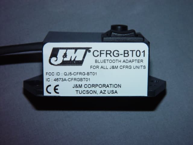
QJ5-CFRG-BT01
Oct 10, 2006Bluetooth Adapter
Equipment Class
DSS - Part 15 Spread Spectrum Transmitter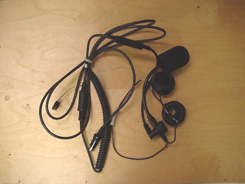
QJ5-JMCB-2003
Aug 27, 2003Motorcycle Mount Mobile CB Transceiver
Equipment Class
TNB - Licensed Non-Broadcast Station Transmitter