QJ5JMHS-WLS465Motorcycle Helmet Bluetooth Intercom Headset
J&M Corporation
Click to zoom
Application Details
- Equipment Class
- DSS - Part 15 Spread Spectrum Transmitter
- Date of Grant
- Mar 19, 2013
- Application Purpose
- Original Equipment
- Date of Application
- Mar 19, 2013
- Equipment Note
- Motorcycle Helmet Bluetooth Intercom Headset
- Frequency Range
- 2402.00000000 - 2480.00000000
- Company
- J&M Corporation
- Country
- United States
Documents & Files
Document Text
Text extracted from the exhibit documents filed with the FCC. Open a document above to read the original.
Users Manual
User Manual Ver 3.1 Motorcycle Helmet Headsets INTRODUCTION Thank you for having chosen the JMHS-WLS465 Bluetooth headset for bikers. This Manual will help you operate the headset ,but you should first familiarize yourself with the Bluetooth functionality of your cellu- lar phone and/or GPS device before using the headset. The retail box of the JMHS-WLS465 contains one headset unit. When paired with another JMHS-WLS465 ,the head- sets can be used as an intercom at a rang of up to 500m. The JMHS-WLS465 offers the following uses: 1. Bluetooth headset for mobile phone communication, supporting headset*and Handsfree * profiles(10m range) 2. Bike-to-Bike Intercom Communication with another JMHS-WLS465 unit(up to 100m or 500m range)in Full Duplex**mode [ purchased separately] 3. Turn-by-Turn GPS Navigation instructions and Streaming Audio from compatible Bluetooth devices 4. FM Radio - built in FM radio receiver 5. Bluetooth stereo - enjoy stereo music from your A2DP enabled device (like cell phone ). The JMHS-WLS465 can establish an audio connection with one Bluetooth device at a time. Please read the section “Using the Headset” to see how you can switch the audio connection between the paired devices. *Mobile phones that do not support the Bluetooth handsfree profile may prevent you from using the Redial and Call Reject features. **Full duplex calls allow you to speak and hear the other party speak simultaneously - 1 - CONTENTS OF RETAIL BOX Headset Helmet clamp NOTE: The use of two speakers may be illegal in certain jurisdictions. Please check the local regulations and act accordingly. Right Speaker (long cord) Microphone Left Speaker (short cord) Sliding Plate CTRL-Control Button --Power On,Power Off, --Intercom call MC-Multi-Connection --Radio On/Off --Answer/Call End/ NRLast umber edialing Volume Up Charging Jack Volume Down - 2 - Wall Charger Allen Wrench Velcro Pads Glue Plate Microphone Sponges User Guide IMPORTANT: The is a water-resistant device, designed for use under moderate rain or snow conditions. However,the headset is not waterproof and should not be used under severe weather condi- tions. The cover tongue protecting the Charging Jack should be kept tightly JMHS-WLS465 BEFORE USING(CHARGING THE HEADSET) Make sure that the headset is fully charged for at least five hours before initial use. 1.Connect the wall charger to the headset's Charging Jack(located between the two Volume Buttons). 2.While charging ,the Red Light turns on. When charging is complete, the Red Light will turn off. - 3 - SET UP AND CONFIGURATION SET UP FOR BIKE-TO-BIKE INTERCOM: PAIRING The can be paired with up to two other headsets for intercom communication. Pairing is a one time process. Once the headsets are paired during this Setup Procedure, they will remain paired and automatically recognize each other whenever they are within range. NOTE: The allows you to speake via intercom to one Buddy headerset at a time. JMHS-WLS465 JMHS-WLS465 STEP1 - 4 - Rider-to-Passenger Full Duplex Intercom Connection JMHS-WLS465 Headset Embedded FM Radio Bike-to-Bike Intercom Mobile Phone GPS BUDDY PAIRIG(requires two headsets) 1. If either headset is turned OFF, press and hold the CTRL Button until the Red/Blue light flashes alternately. 2. Short press CTRL button, it will search the other one which in pairing state and try to pair with it. 3. Within a few seconds, both headsets will turn off Red light, and then begin flashing slowly in Blue, thus pairing is finished. 4. To pair with another headset, repeat above steps. NOTE: If the Pairing process is not completed within one minute the headset will return to Standby mode. STEP 2 SET UP FOR MOBILE PHONE CALLS: PAIRING If you have a Bluetooth enabled mobile phone and would like to make and receive phone calls using the JMHS-WLS465, you must first pair your headset to the mobile phone. Pairing is a once time process. Once the headset is paired to a specific mobile phone during this Setup Procedure, they will remain paired and automatically recognize each other whenever they are within range. If the connection between the phone and headset is lost, tap the CTRL button to reconnect the devices. TO PAIR THE JMHS-WLS465 TO A BLUETOOTH MOBILE PHONE 1. Tune on your phone and make sure its Bluetooth function is activated. 2.With the JMHS-WLS465 headset turned off, press and hold the CTRL Bluetooth for at least six seconds until the Red and Blue Light begin rapidly alternating. 3.Search for Bluetooth devices on your phone by following the phone's instructions. Please consult your phone's User Manual for more information. JMHS-WLS465 - 5 - 4.After a few seconds the phone will list the JMHS-WLS465 as a discovered device. Select it and follow your phone's instruc- tions to accept the pairing. 5.When prompted enter 0000 (four zeros) as your PIN or passkey. 6.Your phone will confirm that pairing has succeeded and the headset will begin flashing slowly in Blue. With some mobile phone, you may need to tap the CTRL button to con- nect the headset to the phone after pairing is complete. The JMHS- WLS465 headset will automatically connect to the last phone con- nected to the headset. STEP 3: SET UP FOR BLUETOOTH GPS DEVICE:PAIRING If you have a Bluetooth enabled GPS device and would like to transmit navigation instructions and sounds from the GPS device through the headset's speakers, you must first pair your headset to the GPS device . NOTE: Not all Bluetooth enabled GPS devices allow connections to Bluetooth headsets like the JMHS-WLS465.Please consult your GPS device's User Manual for more information. TO PAIR THE JMHS-WLS465 TO A BLUETOOTH GPS DEVICE: 1. Turn on your GPS device. 2. With the JMHS-WLS465 headset turned off, press and hold the CTRL Button for at least six seconds until the Blue light begin rapidly alternating. 3. Search for Bluetooth headsets on your GPS device by follow- ing the device's instructions. Please consult your GPS device's User Manual for more information. 4. I…
Text truncated - open the document above for the full version.
Cover Letter(s)
SCS-F18: Project and Product Certification Representative Authorization Letter Page 1 of 2 Rev 3.0 775 Montague Expressway Milpitas, CA 95035 Tel: 408-526-1188 Fax: 408-526-1088 Email: [email protected] Project and Product Certification Representative Authorization Letter Reason for Amendment (current / obsolete) Revision History Approved Date From To Initial Release (obsolete) 1.0 1.0 Nov-14-2006 Revised wording (obsolete) 1.0 2.0 Sept–25-2007 Updated company template (current) 2.0 3.0 Jan-31-2012 SCS-F18: Project and Product Certification Representative Authorization Letter Page 2 of 2 Rev 3.0 2013/3/10 To: SIEMIC, INC. 775 Montague Expressway, Milpitas, CA 95035 USA Dear Sir/Madam, Re: Project and Product Certification Representative Authorization Letter We, _____ J&M Corporation _____hereby authorize SIEMIC, INC. to act as a Certification Body for certifying for the following project(s): Product: Motorcycle Helmet Bluetooth Intercom Headset Trade Name: N/A Model Name: JMHS-WLS465 FCC ID: QJ5JMHS-WLS465 We affirm that between SIEMIC and ___ J&M Corporation ___, any difference in understanding, including test plan, measurement methods, applicable standards and relevant procedures and processes have been resolved prior to commencement of testing activities. Sincerely, Client’s signature Client’s name / title : John.J. Lazzeroni / President Contact information / address : 1415 South Cherry Avenue, Tucson, Arizona 85713, United States
Cover Letter(s)
SCS-F19: Confidentiality Request Letter Page 1 of 2 Rev 3.0 775 Montague Expressway Milpitas, CA 95035 Tel: 408-526-1188 Fax: 408-526-1088 Email: [email protected] Confidentiality Request Letter Reason for Amendment (current / obsolete) Revision History Approved Date From To Initial Release (obsolete) 1.0 1.0 Nov-14-2006 Adding CFR 2.459 (obsolete) 1.0 2.0 August – 11 - 2008 Updated company template & Added text box (current) 2.0 3.0 Jan-31-2012 SCS-F19: Confidentiality Request Letter Page 2 of 2 Rev 3.0 2013/3/10 To: Federal Communications Commission Authorization and Evaluation Division 7435 Oakland Mills Road Columbia, MD Subject: Permanent Confidentiality Request for FCC ID: QJ5JMHS-WLS465 We hereby request confidential treatment of information accompanying this application as outlined below: - Block Diagram - Schematics - Operational Description The above materials contain trade secrets and proprietary information not customarily released to the public. The public disclosure of these materials may be harmful to the applicant and provide unjustified benefits to its competitors. The applicant understands that pursuant to Section 0.457 & 0.459 of the Rules, disclosure of this application and all accompanying documentation will not be made before the date of the Grant for this application. Sincerely, Client’s signature Client’s name / title : John.J. Lazzeroni / President Contact information / address : 1415 South Cherry Avenue, Tucson, Arizona 85713, United States
External Photos
APPENDIX-PHOTOGRAPHS OF EUT CONSTRUCTIONAL DETAILS Photo 1 Photo 2 Photo 3 Photo 4 Photo 5 Photo 6
ID Label/Location Info
W:H=3.2*0.3 FCC ID: QJ5JMHS-WLS465
Internal Photos
Photo 7 Photo 8 Photo 9 Photo 10 Antenna Photo 11 Photo 12 Photo 13 Photo 14
RF Exposure Info
FCC ID: QJ5JMHS-WLS465 RF EXPOSURE EVALUATION METHOD SAR Test Exclusion Thresholds for 100 MHz – 6 GHz and ≤ 50 mm Approximate SAR Test Exclusion Power Thresholds at Selected Frequencies and Test Separation Distances are illustrated in the following Table. Maximum measured transmitter power Frequency (MHZ) Max Antenna Gain (dBm) EIRP (dBm) EIRP (mW) 2402 0 0.254 1.06 2441 0 0.895 1.23 2480 0 1.011 1.26 Refer to 447498 25 D01 General RF Exposure Guidance v05 Appendix A, you see that for Maximum Conducted Output Power 1.26 mW(<10mW), so no SAR is required.
Test Report
FCC RADIO TEST REPORT FCC ID: QJ5JMHS-WLS465 Of Product: Motorcycle Helmet Bluetooth Intercom Headset Trade Name: N/A Model Number: JMHS-WLS465 Serial Model: N/A Report No.: NTEK-2013NT0313054R Prepared for J&M Corporation 1415 South Cherry Avenue, Tucson, Arizona 85713, United States Prepared by Shenzhen NTEK Testing Technology Co., Ltd. 1/F, Building E, Fenda Science Park, Sanwei Community, Xixiang Street Bao’an District, Shenzhen P.R. China Tel.: +86-0755-61156588 Fax.: +86-0755-61156599 Website:www.ntek.org.cn Page 2 of 54 Report No.: NTEK-2013NT0313054R TEST RESULT CERTIFICATION Applicant’s name ................. : J&M Corporation Address ................................. : 1415 South Cherry Avenue, Tucson, Arizona 85713, United States Manufacture's Name ............ : J&M Corporation Address ................................. : 1415 South Cherry Avenue, Tucson, Arizona 85713, United States Product description Product name............................ : Motorcycle Helmet Bluetooth Intercom Headset Model and/or type reference : JMHS-WLS465 Serial Model: N/A Standards ............................. : FCC Part15.247 Test procedure ............................... : ANSI C63.4-2003 This device described above has been tested by NTEK, and the test results show that the equipment under test (EUT) is in compliance with the FCC requirements. And it is applicable only to the tested sample identified in the report. This report shall not be reproduced except in full, without the written approval of NTEK, this document may be altered or revised by NTEK, personal only, and shall be noted in the revision of the document. Date of Test ........................................... : Date (s) of performance of tests ............. : 06 Mar. 2013 ~10 Mar. 2013 Date of Issue .......................................... : 11 Mar 2013 Test Result.............................................. : Pass Testing Engineer : (Apple Huang) Technical Manager : (Tom Zhang) Authorized Signatory : (Bovey Yang) Page 3 of 54 Report No.: NTEK-2013NT0313054R Table of Contents Page 1 . SUMMARY OF TEST RESULTS 5 1.1 TEST FACILITY 6 1.2 MEASUREMENT UNCERTAINTY 6 2 . GENERAL INFORMATION 7 2.1 GENERAL DESCRIPTION OF EUT 7 2.2 DESCRIPTION OF TEST MODES 9 2.3 TABLE OF PARAMETERS OF TEXT SOFTWARE SETTING 9 2.4 BLOCK DIGRAM SHOWING THE CONFIGURATION OF SYSTEM TESTED 10 2.5 DESCRIPTION OF SUPPORT UNITS(CONDUCTED MODE) 11 2.6 EQUIPMENTS LIST FOR ALL TEST ITEMS 12 3 . EMC EMISSION TEST 13 3.1 CONDUCTED EMISSION MEASUREMENT 13 3.1.1 POWER LINE CONDUCTED EMISSION LIMITS 13 3.1.2 TEST PROCEDURE 14 3.1.3 DEVIATION FROM TEST STANDARD 14 3.1.4 TEST SETUP 14 3.1.5 EUT OPERATING CONDITIONS 14 3.1.6 TEST RESULTS 15 3.2 RADIATED EMISSION MEASUREMENT 17 3.2.1 RADIATED EMISSION LIMITS 17 3.2.2 TEST PROCEDURE 18 3.2.3 DEVIATION FROM TEST STANDARD 18 3.2.4 TEST SETUP 19 3.2.5 EUT OPERATING CONDITIONS 20 3.2.6 TEST RESULTS (BELOW 30 MHZ) 21 3.2.7 TEST RESULTS (BETWEEN 30M – 1000 MHZ) 22 3.2.8 TEST RESULTS (ABOVE 1000 MHZ) 24 3.2.9 TEST RESULTS (RESTRICTED BANDS REQUIREMENTS) 30 4 . NUMBER OF HOPPING CHANNEL 34 4.1 APPLIED PROCEDURES / LIMIT 34 4.1.1 TEST PROCEDURE 34 4.1.2 DEVIATION FROM STANDARD 34 4.1.3 TEST SETUP 34 4.1.4 EUT OPERATION CONDITIONS 34 4.1.5 TEST RESULTS 35 5 . AVERAGE TIME OF OCCUPANCY 36 Page 4 of 54 Report No.: NTEK-2013NT0313054R Table of Contents Page 5.1 APPLIED PROCEDURES / LIMIT 36 5.1.1 TEST PROCEDURE 36 5.1.2 DEVIATION FROM STANDARD 36 5.1.3 TEST SETUP 36 5.1.4 EUT OPERATION CONDITIONS 36 5.1.5 TEST RESULTS 37 6 . HOPPING CHANNEL SEPARATION MEASUREMENT 43 6.1 APPLIED PROCEDURES / LIMIT 43 6.1.1 TEST PROCEDURE 43 6.1.2 DEVIATION FROM STANDARD 43 6.1.3 TEST SETUP 43 6.1.4 EUT OPERATION CONDITIONS 43 6.1.5 TEST RESULTS 44 7 . BANDWIDTH TEST 46 7.1 APPLIED PROCEDURES / LIMIT 46 7.1.1 TEST PROCEDURE 46 7.1.2 DEVIATION FROM STANDARD 46 7.1.3 TEST SETUP 46 7.1.4 EUT OPERATION CONDITIONS 46 7.1.5 TEST RESULTS 47 8 . PEAK OUTPUT POWER TEST 49 8.1 APPLIED PROCEDURES / LIMIT 49 8.1.1 TEST PROCEDURE 49 8.1.2 DEVIATION FROM STANDARD 49 8.1.3 TEST SETUP 49 8.1.4 EUT OPERATION CONDITIONS 49 8.1.5 TEST RESULTS 50 9 . ANTENNA REQUIREMENT 52 9.1 STANDARD REQUIREMENT 52 9.2 EUT ANTENNA 52 10 . EUT TEST PHOTO 53 APPENDIX-PHOTOGRAPHS OF EUT CONSTRUCTIONAL DETAILS Page 5 of 54 Report No.: NTEK-2013NT0313054R 1. SUMMARY OF TEST RESULTS Test procedures according to the technical standards: FCC Part15 (15.247) , Subpart C Standard Section Test Item Judgment Remark 15.207 Conducted Emission PASS 15.247(a)(1) Hopping Channel Separation PASS 15.247(b)(1) Peak Output Power PASS 15.247(c) Radiated Spurious Emission PASS 15.247(a)(iii) Number of Hopping Frequency PASS 15.247(a)(iii) Dwell Time PASS 15.247(a)(1) Bandwidth PASS 15.205 Band Edge Emission PASS 15.203 Antenna Requirement PASS NOTE: (1)” N/A” denotes test is not applicable in this Test Report Page 6 of 54 Report No.: NTEK-2013NT0313054R 1.1 TEST FACILITY NTEK Testing Technology Co., Ltd Add. : 1/F, Building E, Fenda Science Park, Sanwei Community, Xixiang Street, Bao’an District, Shenzhen P.R. China. FCC Registration No.:238937; IC Registration No.:9270A-1 CNAS Registration No.:L5516 1.2 MEASUREMENT UNCERTAINTY The reported uncertainty of measurement y ± U,where expended uncertainty U is based on a standard uncertainty multiplied by a coverage factor of k=2,providing a level of confidence of approximately 95 %。 No. Item Uncertainty 1 Conducted Emission Test ±1.38dB 2 RF power,conducted ±0.16dB 3 Spurious emissions,conducted ±0.21dB 4 All emissions,radiated(<1G) ±4.68dB 5 All emissions,radiated(>1G) ±4.89dB 6 Temperature ±0.5°C 7 Humidity ±2% Page 7 of 54 Report No.: NTEK-2013NT0313054R 2. GENERAL INFORMATION 2.1 GENERAL DESCRIPTION OF EUT Equipment Motorcycle Helmet Bluetooth Intercom Headset Trade Name N/A Model Name JMHS-WLS465 Serial Model N/A Model Difference N/A Product Description The EUT is a Motorcycle Helmet Bluetooth Intercom Headset Operation Frequency: 2402~2480 MHz Modulation Type: FHS…
Text truncated - open the document above for the full version.
Test Setup Photos
Page 52 of 53 Report No.: NTEK-2013NT0313054R 9. EUT TEST PHOTO Radiated Measurement Photos Page 53 of 53 Report No.: NTEK-2013NT0313054R Conduction Measurement Photos
Contact Information
Applicant
John J Lazzeroni(President)
Test Firm
NTEK Testing Technology Co., Ltd.Wetow Huang
Technical Specifications
| # | Rule Parts | Frequency Range | Power Output |
|---|---|---|---|
| 1 | 15C | 2.40 GHz - 2.48 GHz | 1.26 mW |
Other Applications from J&M Corporation
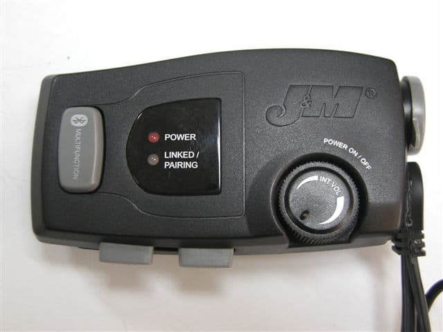
QJ5-HS-BLU
May 28, 2007Bluetooth Device
Equipment Class
DSS - Part 15 Spread Spectrum Transmitter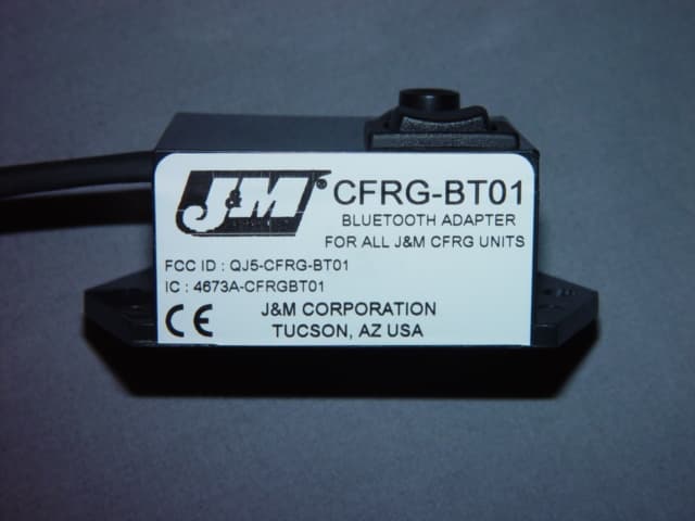
QJ5-CFRG-BT01
Oct 10, 2006Bluetooth Adapter
Equipment Class
DSS - Part 15 Spread Spectrum Transmitter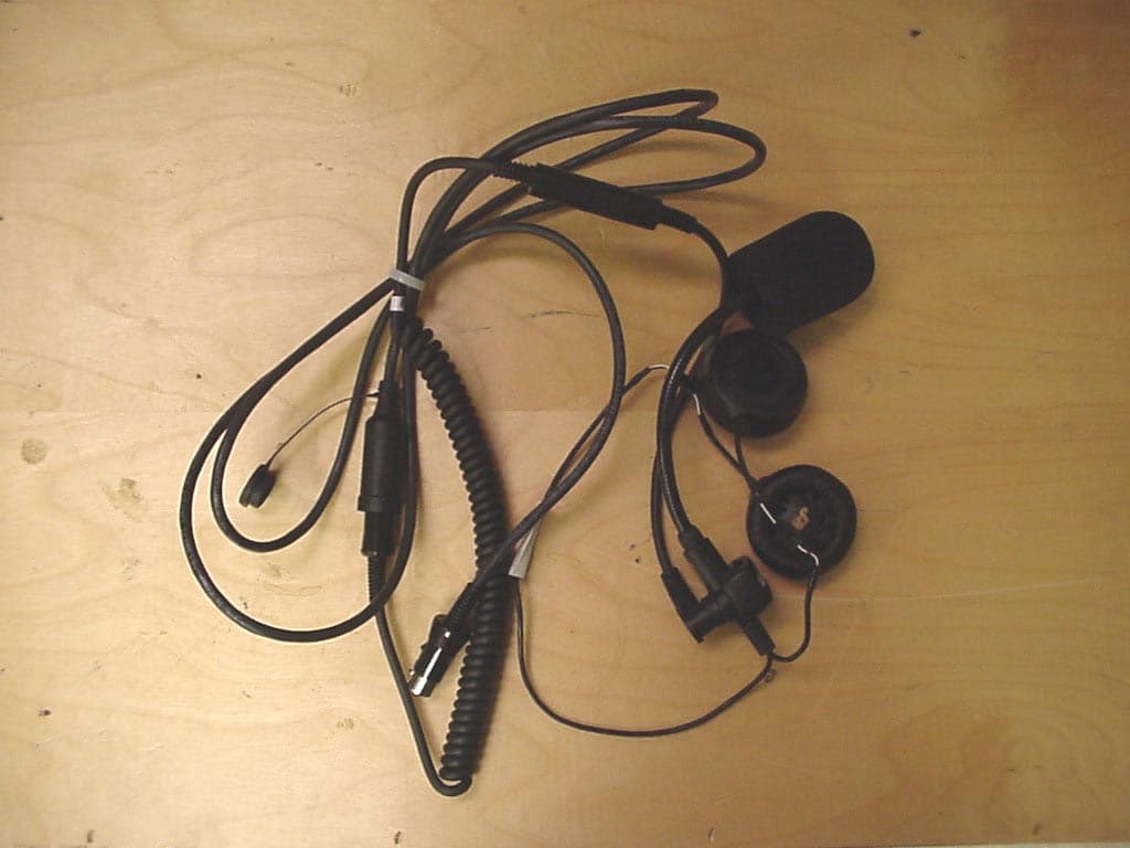
QJ5-JMCB-2003
Aug 27, 2003Motorcycle Mount Mobile CB Transceiver
Equipment Class
TNB - Licensed Non-Broadcast Station Transmitter