QJEAP716102Mesh AP-7161 Outdoor Wireless Access Point
Zebra Technologies Corporation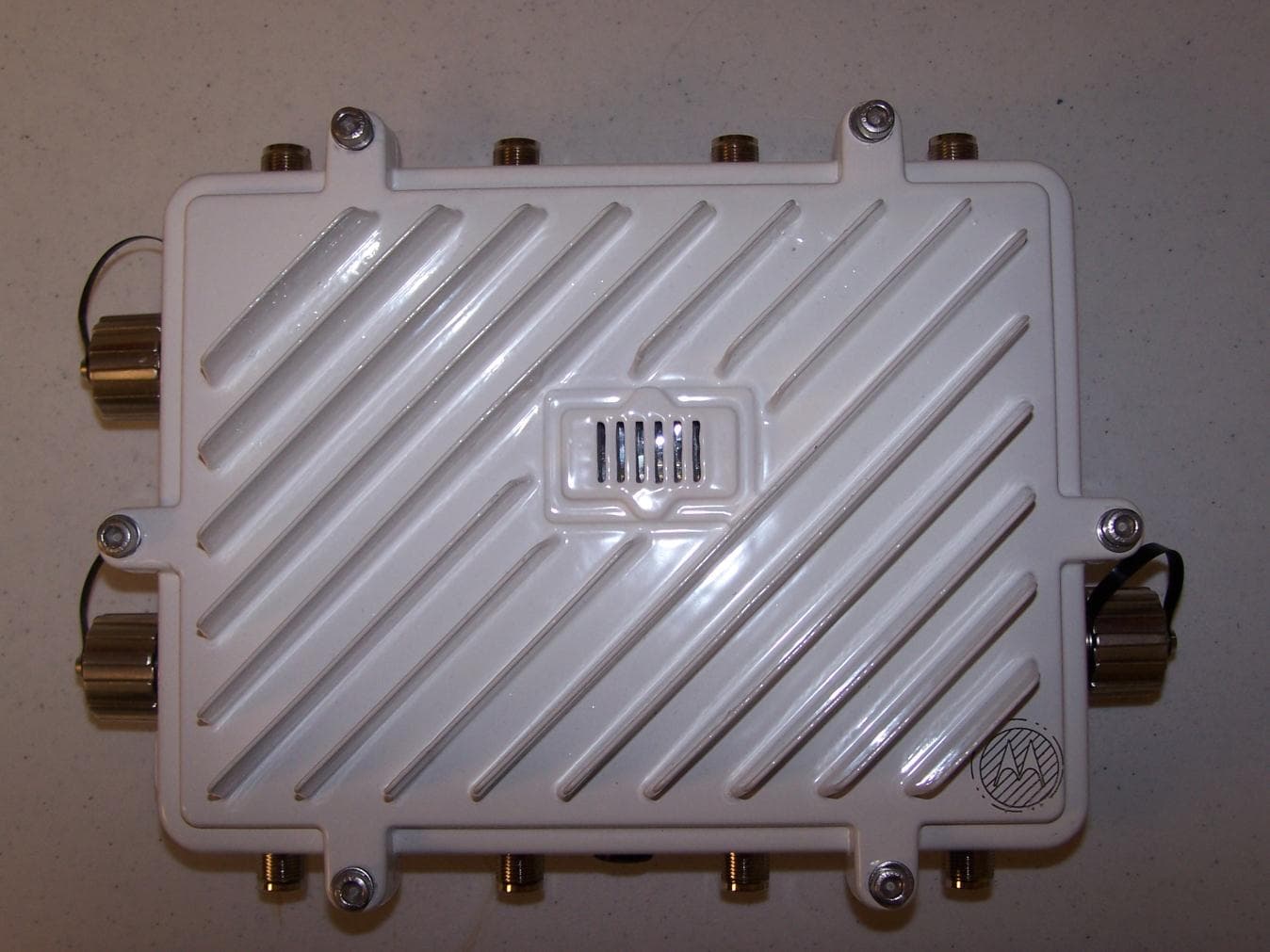
Click to zoom
Application Details
- Equipment Class
- NII - Unlicensed National Information Infrastructure TX
- Date of Grant
- Aug 02, 2011
- Application Purpose
- Original Equipment
- Date of Application
- Aug 02, 2011
- Equipment Note
- Mesh AP-7161 Outdoor Wireless Access Point
- Frequency Range
- 5755.00000000 - 5805.00000000
- Country
- United States
Documents & Files
Document Text
Text extracted from the exhibit documents filed with the FCC. Open a document above to read the original.
Users Manual
AP-7161 ACCESS POINT INSTALLATION GUIDE 2AP-7161 Access Point Installation Guide AP-7161 Access Point Installation Guide3 Motorola Solutions reserves the right to make changes to any product to improve reliability, function, or design. Motorola Solutions does not assume any product liability arising out of, or in connection with, the application or use of any product, circuit, or application described herein. No license is granted, either expressly or by implication, estoppel, or otherwise under any patent right or patent, covering or relating to any combination, system, apparatus, machine, material, method, or process in which Motorola Solutions products might be used. An implied license exists only for equipment, circuits, and subsystems contained in Motorola Solutions products. Service Information If you have a problem using the equipment, contact your facility’s Technical or Systems Support. If there is a problem with the equipment, they will contact the Motorola Solutions Support at: http://supportcentral.motorola.com. 4AP-7161 Access Point Installation Guide Introduction.......................................................................................................................................... 3 Document Conventions........................................................................................................................ 3 Package Contents................................................................................................................................ 4 Hardware Installation........................................................................................................................... 5 Precautions.......................................................................................................................................... 5 Warnings.............................................................................................................................................. 5 Site Preparation................................................................................................................................... 6 Grounding Requirements..................................................................................................................... 6 AP-7161 Grounding Connection.......................................................................................................... 7 Ethernet and Lightning Protection........................................................................................................ 7 Access Point Placement...................................................................................................................... 7 Antenna Options.................................................................................................................................. 8 Installing an AP-7161......................................................................................................................... 10 Required Tools................................................................................................................................... 10 Mounting Bracket Options.................................................................................................................. 10 Extension Bracket.............................................................................................................................. 11 Pole Mounted Installations................................................................................................................. 13 Wall Mounted Installations................................................................................................................. 16 AP-7161 Connections and Ports.........................................................................................................18 Antenna Connectors........................................................................................................................... 18 Console, GE1/POE and GE2 Ports.................................................................................................... 19 Grounding Screw................................................................................................................................ 20 LED Indicators.................................................................................................................................... 21 Three Radio LEDs.............................................................................................................................. 22 Dual Radio LEDs................................................................................................................................ 23 Installing the Power-Over Ethernet (PoE) Unit................................................................................... 24 PoE Unit Specifications...................................................................................................................... 24 PoE Interface Connections................................................................................................................ 25 Installing the PoE Unit........................................................................................................................ 25 Basic AP-7161 Configuration............................................................................................................. 26 Specifications..................................................................................................................................... 26 Regulatory Compliance...................................................................................................................... 30 Country Approvals.............................................................................................................................. 30 Health and Safety Recommendations................................................................................................ 30 Warnings …
Text truncated - open the document above for the full version.
Cover Letter(s)
Motorola, Inc 1064 Greenwood Blvd Suite 400 • Lake Mary, Florida 32746-5418 • USA • Tel: +1 407 562-4000 www.motorola.com 4/8/2011 MET Laboratories, Inc. 914 West Patapsco Avenue Baltimore, MD 21230 RE: CONFIDENTIALITY REQUEST FOR AP7161 (FCC ID: QJEAP716102) To Whom It May Concern: This letter serves as an official request for confidentiality under sections 0.457 and 0.459 of CFR 47. We have requested that the following items required to be submitted with this application be permanently withheld from pubic review. Block diagrams Schematics/PCB/circuit diagrams Parts lists/BOM Tune-up procedures Operational descriptions These items are Motorola proprietary intellectual property that should not be placed in the possession by our competition. Please contact me if there is any information you may need. Sincerely, Robert Greenway Motorola, Inc 1064 Greenwood Blvd Suite 400 • Lake Mary, Florida 32746-5418 • USA • Tel: +1 407 562-4000 www.motorola.com
Cover Letter(s)
Regulatory Engineering Motorola Inc., One Motorola Plaza, | Holtsville, NY 11742 | 1.631.738.2400 phone | 1.631.627.7179 fax | www.motorola.com July 20, 2011 Federal Communications Commission Office of Engineering and Technology Equipment Authorization Division 7345 Oakland Mills Road Columbia MD 21046 Subject: Declarations and attestations for Radio Modules with FCC IDs: QJEAP716101, QJEAP716102 To the Commission: 1. TPC Declaration: We, the undersigned, attest that this device does support “TPC” Transmit Power Control in the 5 GHz UNII bands. The software and associated drivers to support TPC are built into the device firmware, with no mechanism to disable or turn off TPC. 2. Restricted Access to software and controls to set the Frequency and or disable DFS Declaration We, the undersigned, attest that this device does not support access, by any party (End User or Professional Installer), to set the frequency or disable DFS. A US specific version of this product will be sold for use in the US. This US version will only support US frequencies listed on the FCC Grant, the “Country Selection List” for this unit only has US listed. There are no controls or selections in the product firmware that can turn off/disable DFS. 3. The following Channel / Frequency Plan is implemented in this Device for Parts 15.247, 15.407 and 90Y operation. No DFS frequencies are configurable by an End User or Professional Installer. Supports Supports DFS Channel Frequency Active Scanning Passive Scanning (Master) (MHz) 1 2412 N/A N/A N/A 2 2417 N/A N/A N/A 3 2422 N/A N/A N/A 4 2427 N/A N/A N/A 5 2432 N/A N/A N/A 6 2437 N/A N/A N/A 7 2442 N/A N/A N/A 8 2447 N/A N/A N/A 9 2452 N/A N/A N/A 10 2457 N/A N/A N/A 11 2462 N/A N/A N/A 21 4955 N/A N/A N/A Regulatory Engineering Motorola Inc., One Motorola Plaza, | Holtsville, NY 11742 | 1.631.738.2400 phone | 1.631.627.7179 fax | www.motorola.com 25 4975 N/A N/A N/A 149 5745 N/A N/A N/A 153 5765 N/A N/A N/A 157 5785 N/A N/A N/A 161 5805 N/A N/A N/A 165 5825 N/A N/A N/A 4. Ad-Hoc Declaration: We, the undersigned, attest that this device does not support Ad-Hoc operation on any channel or frequency. 5. Declaration of Part 15 Subpart B Compliance We Motorola Inc., as the grantee of this device would like to declare that the composite portion categorized as computer peripheral has been authorized under the Declaration of Conformity procedures. 6. 5.60 -5.65 GHz Restricted band Declaration We, the undersigned, attest that this device does not support operation in the 5.60 – 5.65 GHz band. The firmware on the device restricts the operation in this frequency band and does not utilize the channels in this band. Respectfully, Mark S. Luksich DMTS, Regulatory Engineering 631-738-5134 [email protected]
Cover Letter(s)
Motorola, Inc 1064 Greenwood Blvd Suite 400 • Lake Mary, Florida 32746-5418 • USA • Tel: +1 407 562-4000 www.motorola.com 4/8/2011 MET Laboratories, Inc. 914 West Patapsco Avenue Baltimore, MD 21230 RE: CONFIDENTIALITY REQUEST FOR AP7161 (FCC ID: QJEAP716102) To Whom It May Concern: In accordance with sections 0.457 and 0.459 of CFR 47, Motorola Inc., requests short-term Confidentiality of the following sections of this application for a period of 45 days after grant is issued. Test setup photos External photos Internal photos User’s manual The documents contain detailed system and equipment descriptions and related information about the product, which Motorola Inc. considers to be proprietary, confidential, and a custom design and otherwise, would not release to the general public. Since the design is a basis from which future technological products will evolve, Motorola Inc. feels that this information would be of benefit to its competitors, and that the disclosure of the information in these documents would give our competitors an unfair advantage in the market. Please contact me if there is any information you may need. Sincerely, Robert Greenway Motorola, Inc 1064 Greenwood Blvd Suite 400 • Lake Mary, Florida 32746-5418 • USA • Tel: +1 407 562-4000 www.motorola.com
Cover Letter(s)
Tim Dwyer <[email protected]>Mon, Jun 6, 2011 at 5:26 PM To: Jenn Warnell <[email protected]> Hi Jenn, I have made my way through most of the FCC application. It appears mostly complete, but there are some items that are not clear so I am sending the following questions before making it final. Completion of the review may depend on the replies. 1-4 are needed. Best regards, Tim Block diagram does not appear to show RF portion or antenna interface.It should show the antenna interfaces for all 8 antennas shown in the photo exhibits and present a clear image of what is being certified. 1. The block diagram, theory of operation, schematics etc.do not present a clearpicture of how this AP operates.It has 8 antenna ports, but how are the 8 antennas configured for operation? It is assumed that thisAP is running in some kind of MIMO mode, but the details are not clear in any of the documents. 2. Output power port to port variation is 2 to 3 dB for MIMO operation in each of the3test reports.This is unusual.Is there an explanation? 3. Is the hardware identical for all transmitters?4. The following information will be helpful in understanding the device?5. W hat is the maximum number of transmitters per box?2 3x3 transmitters?Remaining two ports?6. Same information sent to different transmitters at the same time?7. Sector antennas?8. Beam forming?9. Point-to-Point, Point-to-Multipoint?10. W ill a single box be capable of operation on all bands?11. Antenna arrangement and collocation?12. [Quoted text hidden] Jenn Warnell <[email protected]>Thu, Jun 9, 2011 at 12:39 PM To: Tim Dwyer <[email protected]> Hi Tim, Below are the customer responses. The customer sent a large folder of information and I believe the attached documents are what you are looking for. Please let me know. Jenn Warnell Documentation/TCB Administrator MET Laboratories, Inc. (410) 949-1877 (direct) From:[email protected] [mailto:[email protected]]On Behalf OfTim Dwyer Sent: Monday, June 06, 2011 5:27 PM To: Jenn Warnell Subject: Re: Technical Review Request: Job 30461 - Motorola Hi Jenn, I have made my way through most of the FCC application. It appears mostly complete, but there are some items that are not clear so I am sending the following questions before making it final. Completion of the review may depend on the replies. 1-4 are needed. Best regards, Tim Block diagram does not appear to show RF portion or antenna interface. It should show the antenna interfaces for all 8 antennas shown in the photo exhibits and present a clear image of what is being certified. 1. The customer will expand the block diagram to show the RF portion. The block diagram, theory of operation, schematics etc. do not present a clear picture of how this AP operates. It has 8 antenna ports, but how are the 8 antennas configured for operation? It is assumed that thisAP is running in some kind of MIMO mode, but the details are not clear in any of the documents. 2. the details are not clear in any of the documents. The customer will expand the theory of operations document as well to present a clearer picture. Output power port to port variation is 2 to 3 dB for MIMO operation in each of the3test reports. This is unusual. Is there an explanation? 3. I am still waiting on clarification on this one. Is the hardware identical for all transmitters?4. Yes, there are three identical radios, each with three identical transmitters. Oneof the transmitters on one of the radios is software disabled, and is not connected to an antenna, so only 8 antenna ports are needed. See below for more detail. The following information will be helpful in understanding the device?5. W hat is the maximum number of transmitters per box? 2 3x3 transmitters? Remainingtwo ports?6. Two of the three identical radios are used as 3x3 transmitters for data traffic, one each in the 2.4 and 5.x GHz bands. Three single-band, Omni antennas are used for each radio. The third radio is electronically identical, but is used as a sensor in both bands to identify unauthorized client associations. It issoftware configured as a 2x2 (one tx/rx chain is software disabled), and is connected to two 2.4/5.x dual-band antennas. Same information sent to different transmitters at the same time?7. Yes, the MAC and PHY layers of each radio operate in compliance with the IEEE 802.11b, a, g and n specifications, and in all model configurations transmit either identical information on all antennas, or unique linear combinations of the same information on all antennas. Sector antennas?8. No, only omni-directional. Beam forming?9. No. Point-to-Point, Point-to-Multipoint?10. No, only omni-directional. W ill a single box be capable of operation on all bands?11. Under software control, one of the two data radios will operate in the 2.4 band, the other data radio will operate in the 4.9/5.x bands, and the third (sensor) radio may operate in any of the 2.4/4.9/5.x bands Antenna arrangement and collocation?12. A linear array of three antennas is used for each data radio (one array on each side of the box), while the third radio's 2 dual-band antennas are arranged one on each side of the box. [Quoted text hidden] 4 attachments AP7131N_Block_Diagram.pdf 20K AP7131N_TCF_Theory_of_Operation.pdf 260K MB82 THEORY OF OPERATION rev4.pdf 788K MB82_Block_Diagram.pdf 14K Tim Dwyer <[email protected]> Technical Review Request: Job 30461 - Motorola 36 messages Jenn Warnell <[email protected]>Tue, May 31, 2011 at 10:52 AM To: Tim Dwyer <[email protected]> Cc: Jenn Warnell <[email protected]> Hello Tim, Please accomplish the technical review for this FCC and IC certification with the following information: Site:ftp.metlabs-int.com User: mettcb Password: 92my6kh1 Folder:Motorola - 30461 Please keep in mind that the application should be reviewed within 24 – 48 hours. Let me know if I should provide you with anything else, or if there may be any delays you may foresee in reviewing. The customer will be fili…
Text truncated - open the document above for the full version.
External Photos
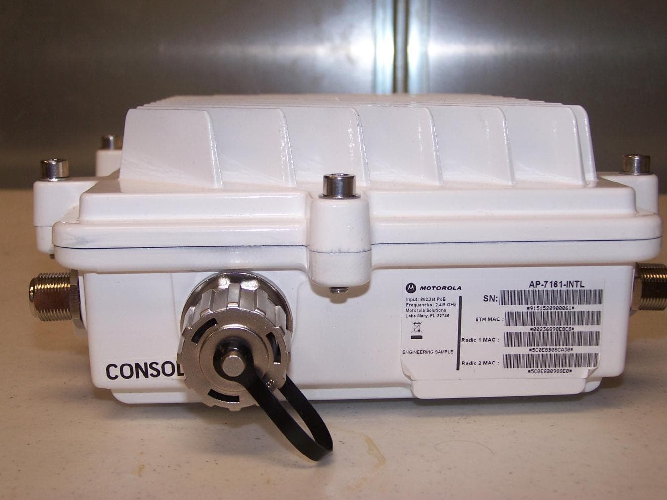
Photograph 1. Top Exterior Photograph 2. Bottom Exterior Photograph 3. Antennae and Cable Photograph 4. Left Exterior Photograph 5. Right Exterior Photograph 6. POE Ports Photograph 7. Console Ports Photograph 8. One Side Antennae Photograph 9. Other Side Antennae Photograph 10. Radio 1 Ports Photograph 11. Radio 2 Ports
ID Label/Location Info
AP-7161 Label Review Feb 24, 2011 Serial Number Label Location US Model P/N AP-7161-66S40-USS/NETH MACR1 MACR2 MACR3 MAC Model number options: AP- 7161-66040-US, AP-7161-66S40-US Use DC Symbol after 48VTwo Radio model (AP-7161-6604 0-US ) will not have R3 MAC Regulatory Label Location US Model I.T.EE333002 FCC ID: QJEAP716101IC: 4602A-AP716101 Made in China Holtsville, NY 11742 Model: AP-716148V --- 0.75A2.4/5GHz Serial Number Label Location WR – Worldwide RoHS Model P/N AP-7161-66S40-WRS/NETH MACR1 MACR2 MACR3 MAC Model number options: AP-7161- 66040-WR, AP-7161-66S40-WR Use DC Symbol after 48VTwo Radio model (AP-7161-6604 0-WR) will not have R3 MAC Holtsville, NY 11742 Regulatory Label Location WR – Worldwide RoHS Model I.T.EE333002 Made in China Model: AP-716148V --- 0.75A2.4/5GHz Shipping Container P/N options: AP-7161-66040-US, AP-7161-66S40-US, AP-7161-66040-WR, AP-7161-66S40-WRPlace CE Mark on –WR models. Place MAC addresses on label below S/N.
Internal Photos
Photograph 1. Interior with cnxns Photograph 2. board bottom Photograph 3. interior bottom Photograph 4. board without radios Photograph 5. board without radios 2 Photograph 6. radio on board Photograph 7. under radio Photograph 8. radio with cover Photograph 9. radio without cover Photograph 10. radio and cover Photograph 11. top interior Photograph 12. top interior profile Photograph 13. thermal paste Photograph 14. thermal paste 2
RF Exposure Info
495±5 STAND ALONE CONFIGURATION MAST MOUNT CONFIGURATION WHITE UV FIBERGLASS HOUSING 19 1.5 DIAMETER OVERMOLD 27 1.5 DIAMETER VENTED CAP VENTED CONNECTOR FIXED N-MALE CONNECTOR REVISIONS REV.ECRDESCRIPTIONCHANGED BY/DATEAPPROVED BY/DATE AAINITIAL RELEASES.J. 10/29/10S.J. 10/29/10 DIMENSIONS ARE IN MILLIMETERS ANGLE: 30' 0 PLACE DECIMAL: 0.5 1 PLACE DECIMAL: 0.25 2 PLACE DECIMAL: 0.13 SURFACE ROUGHNESS 1 23456 654321 D C B A D C B A MANCHESTER, NH 03103 USA 10/29/10I. CHICKLISMFG. UNLESS OTHERWISE NOTED, THIS DOCUMENT CONTAINS LAIRD TECHNOLOGIES CONFIDENTIAL INFORMATION. REPRODUCTION, USE, DISCLOSURE OR TRANSMITTAL OF ALL OR ANY PART OF THIS DOCUMENT IS PROHIBITED EXCEPT TO THE EXTENT APPROVED IN WRITING BY AN AUTHORIZED REPRESENTATIVE OF LAIRD TECHNOLOGIES. LAIRD TECHNOLOGIES RESERVES ALL RIGHTS UNDER PATENTS, TRADEMARKS, COPY RIGHTS AND TRADE SECRETS. COPYRIGHT, LAIRD TECHNOLOGIES 2010, ALL RIGHTS RESERVED. S. JOHNSON S2406BFNMMO S2406BFNM PROJ. ENG . DRAWN BY DATE APPROVALS THIRD ANGLE PROJECTION TOLERANCES UNLESS OTHERWISE SPECIFIED INTERPRET DIMENSIONING AND TOLERANCING IN ACCORDANCE WITH ASME Y14.5M-2009 DO NOT SCALE DRAWING SCALE: 1:4PREVIOUS# SHEET 1 OF 1 REV DWG. NO. A3 SIZE TITLE: 10/29/10K. SEARL T. PETROPOULOS 11/1/10 10/29/10 AA MOUNTING AND OUTLINE MATERIAL: FINISH: N/A N/A 1.6 APPL. MECH. REV The component(s), including any plating, finishes, coatings, chemicals and surfaces treatments, supplied in this document/drawing must conform and comply with the latest issue of Laird Technologies Specification LT-GES-001, which fully includes but is not limited to all contents of EU Directives 2002/95/EC (RoHS Directive), as well as includes requirements of the Joint Industry Guide standard JIG-101, April 2005. The component(s) in this document/drawing may be subject to a full compound analysis for proof of compliance. The latest issue of Laird Technologies Specification LT-GES-001, (General Specification for the Environment) is readily available upon request from the supplier.
RF Exposure Info
495.5±2.3 25.40±0.50 25.4±0.3 21.0 MAX DETAIL A SCALE 2 : 2.5 DRAIN SLOTS 2X TYPE-N, MALE CONNECTOR, (COUPLING NUT SPINS FREELY.) MAST MOUNT CONFIGURATION 31.76±0.50 VENTED CAP FOR INVERTED MOUNTING C L REVISIONS REV.ECR #DESCRIPTION CHANGED BY/DATE APPROVED BY/DATE AAINITIAL RELEASEk.s. 10-22-07k.s. 10-22-07 ABMAN-4156CHGND CAP ON RADOME TO 156911-VENTED TO INVERT UNITMCL 08-25-10K.S. 08-25-10 DIMENSIONS ARE IN MILLIMETERS ANGLE: 30' 0 PLACE DECIMAL: 0.5 1 PLACE DECIMAL: 0.25 2 PLACE DECIMAL: 0.13 SURFACE ROUGHNESS 1 23456 654321 D C B A D C B A MANCHESTER, NH 03103 USA 10-23-07A.YERGEAUMFG. UNLESS OTHERWISE NOTED, THIS DOCUMENT CONTAINS LAIRD TECHNOLOGIES CONFIDENTIAL INFORMATION. REPRODUCTION, USE, DISCLOSURE OR TRANSMITTAL OF ALL OR ANY PART OF THIS DOCUMENT IS PROHIBITED EXCEPT TO THE EXTENT APPROVED IN WRITING BY AN AUTHORIZED REPRESENTATIVE OF LAIRD TECHNOLOGIES. LAIRD TECHNOLOGIES RESERVES ALL RIGHTS UNDER PATENTS, TRADEMARKS, COPY RIGHTS AND TRADE SECRETS. COPYRIGHT, LAIRD TECHNOLOGIES 2010, ALL RIGHTS RESERVED. K. SEARL S4908WBFNMMO S4908WBFNM, PROJ. ENG . DRAWN BY DATE APPROVALS THIRD ANGLE PROJECTION TOLERANCES UNLESS OTHERWISE SPECIFIED INTERPRET DIMENSIONING AND TOLERANCING IN ACCORDANCE WITH ASME Y14.5M-2009 DO NOT SCALE DRAWING SCALE: 1:2.5PREVIOUS# SHEET 1 OF 1 REV DWG. NO. A3 SIZE TITLE: 10-22-07S.JOHSON T.PETROPOULOS 10-22-07 08-16-07 AB MOUNTING & OUTLINE MATERIAL: FINISH: N/A N/A 1.6 APPL. MECH. REV The component(s), including any plating, finishes, coatings, chemicals and surfaces treatments, supplied in this document/drawing must conform and comply with the latest issue of Laird Technologies Specification LT-GES-001, which fully includes but is not limited to all contents of EU Directives 2002/95/EC (RoHS Directive), as well as includes requirements of the Joint Industry Guide standard JIG-101, April 2005. The component(s) in this document/drawing may be subject to a full compound analysis for proof of compliance. The latest issue of Laird Technologies Specification LT-GES-001, (General Specification for the Environment) is readily available upon request from the supplier.
RF Exposure Info
OC24527 Dual Band Omni 2.4-2.483, 5.25-5.875 GHz December 1, 2010 VSWR 2 December 1, 2010 1.01.11.21.31.41.51.61.71.81.92.0 2.40 2.42 2.44 2.46 2.48 5.33 5.43 5.53 5.63 5.73 5.83 VSWR Frequency (GHz) Pattern Orientation 3 H-Plane 270°E0-Plane 270° H-Plane 0°E90-Plane 270° E90-Plane 180°E0-Plane 180° H-Plane 90°E0-Plane 90° H-Plane 180°E90-Plane 90° E90-Plane 0°E0-Plane 0° December 1, 2010 Radiation Patterns (2.4 GHz) H-Plane Gain on Horizon = 4.7 dBi Peak Gain = H 4.7 dBi 4 E0-Plane Peak Gain Angle = 88° Beam Width = 27° E90-Plane Peak Gain Angle = 275° Beam Width = 27° December 1, 2010 Radiation Patterns (2.45 GHz) H-Plane Gain on Horizon = 4.9 dBi Peak Gain = H 4.9 dBi 5 E0-Plane Peak Gain Angle = 274° Beam Width = 27° E90-Plane Peak Gain Angle = 274° Beam Width = 26° December 1, 2010 Radiation Patterns (2.483 GHz) H-Plane Gain on Horizon = 4.9 dBi Peak Gain = H 4.9 dBi 6 E0-Plane Peak Gain Angle = 273° Beam Width = 28° E90-Plane Peak Gain Angle = 271° Beam Width = 28° December 1, 2010 Radiation Patterns (5.25 GHz) H-Plane Gain on Horizon = 7.5 dBi Peak Gain = H 7.5 dBi 7 E0-Plane Peak Gain Angle = 271° Beam Width = 16° E90-Plane Peak Gain Angle = 269° Beam Width = 16° December 1, 2010 Radiation Patterns (5.55 GHz) H-Plane Gain on Horizon = 7.5 dBi Peak Gain = H 7.5 dBi 8 E0-Plane Peak Gain Angle = 271° Beam Width = 14° E90-Plane Peak Gain Angle = 269° Beam Width = 15° December 1, 2010 Radiation Patterns (5.875 GHz) H-Plane Gain on Horizon = 7.7 dBi Peak Gain = H 7.7 dBi 9 E0-Plane Peak Gain Angle = 269° Beam Width = 15° E90-Plane Peak Gain Angle = 90° Beam Width = 15° December 1, 2010 Ripple / Gain Performance Comparison Frequency (GHz) 2.4 2.45 2.48 5.25 5.5 5.875 Gain Max / Min Ripple Gain Max / Min Ripple Gain Max / Min Ripple Gain Max / Min Ripple Gain Max / Min Ripple Gain Max / Min Ripple 4.7 / 3.1 1.6 4.9 / 2.8 2.1 4.9 / 3.0 1.9 7.5 / 6.2 1.3 7.5 / 5.8 1.7 7.7 / 5.5 2.2 10 December 1, 2010 11 Test Equipment Summary (VSWR) Analyzer •Agilent E5071B network analyzer•Maximum frequency range: 300 kHz – 8.5 GHz•Calibration certified annually (system)•Calibrated per OSL standard (test) Testing Chamber •36”H x 36”W x 34”D•Absorber material: Pyramid 2”W x 2”L x 5”H / division December 1, 2010 12 Test Equipment Summary (Radiation Patterns) Testing Chamber: • Test chamber is a singl e axis, single source system comprising a network analyzer, positioner / controlle r and tapered anechoic chamber. The system is calibrated prior to each test. All components are calibrated annually as required. • Dimensions: • 8.8 meters from face of source to DUT center of rotation • 72” center of height above floor September 7, 2010
RF Exposure Info
ODC24M-5S ML-2499-FHPA5-01R 2.4 - 2.5 GHz January 14, 2011 VSWR January 14, 2011 2 1.01.11.21.31.41.51.61.71.81.92.0 2.400 2.410 2.420 2.430 2.440 2.450 2.460 2.470 2.480 2.490 2.500 VSWR Frequency (GHz) Pattern Orientation January 14, 2011 3 H Plane 0°E90 Plane 90° H Plane 90°E0 Plane 90° E0 Plane 0°E90 Plane 0° H Plane 180°E90 Plane 270° H Plane 270°E0 Plane 180° E0 Plane 180°E Plane 180° Radiation Patterns (2.4 GHz) H-Plane Gain on Horizon = 5.1 dBi Peak Gain = 5.7 dBi 4 E0-Plane Peak Gain Angle = 273° Beam Width = 32° E90-Plane Peak Gain Angle = 274° Beam Width = 32° January 14, 2011 Radiation Patterns (2.45 GHz) H-Plane Gain on Horizon = 5.3 dBi Peak Gain = 5.6 dBi 5 E0-Plane Peak Gain Angle = 271° Beam Width = 36° E90-Plane Peak Gain Angle = 90° Beam Width = 36° January 14, 2011 Radiation Patterns (2.5 GHz) H-Plane Gain on Horizon = 5.3 dBi Peak Gain = 5.4 dBi 6 E0-Plane Peak Gain Angle = 84° Beam Width = 35° E90-Plane Peak Gain Angle = 86° Beam Width = 36° January 14, 2011 7 Test Equipment Summary (VSWR) Analyzer •Agilent E5071B network analyzer•Maximum frequency range: 300 kHz – 8.5 GHz•Calibration certified annually (system)•Calibrated per OSL standard (test) Testing Chamber •36”H x 36”W x 34”D•Absorber material: Pyramid 2”W x 2”L x 5”H / division January 14, 2011 8 Test Equipment Summary (Radiation Patterns) Testing Chamber: • Test chamber is a singl e axis, single source system comprising a network analyzer, positioner / controlle r and tapered anechoic chamber. The system is calibrated prior to each test. All components are calibrated annually as required. • Dimensions: • 8.8 meters from face of source to DUT center of rotation • 72” center of height above floor January 14, 2011
RF Exposure Info
198 PCTEL Broadband Technology Group WEB: www.antenna.pctel.com The wireless broadband omnidirectional antennas are designed to provide maximum performance and reliability under the toughest weather conditions. These antennas feature a UV stable, vented radome that provides ultimate pr ote ction against weather elements. They can be mast or wall mounted. Features UV stable, pultruded fiberglass radome. Allows outdoor installation even in harsh climates. Vented system design (all models except MFB24012). Provides reliable performance by protecting the electrical design against extreme moisture and/or temperatures. Thread relief on connector (all models, except MFB24012 which has a pigtail). Improved accessibility for taping reduces installation time and improves overall effectiveness. Internal o-ring seal in the base of the antenna with integrated connector at the base. Assures a watertight seal to prevent water from migrating into the antenna connector (all models, except MFB24012 which has a pigtail). Electrical downtilt options on select models. Provide system planners flexibility in challenging operating environments. • • • • • Technical Data Maximum Power: 25 watts Polarization: Vertical Normal Impedance: 50 ohms VSWR: < 1.5:1 Radome Material: UV resistant pultruded fiberglass lightning Protection: Not standard, but all models can be ordered with DC grounding. Add “DC” to the part number to order the antenna with DC grounding. Termination: N female (except MFB24012). N male connector option available. To order, add “NM” to part number. N female, reverse polarity and reverse threaded connectors optional on most models. 16” RG-213 pigtail with N female connector (for model MFB24012 only.) Mounting base Diameter: 1.25 inches (all models except MFB24012) 1.5 inches (model MFB24012) Mounting Method: MMK1924 — L bracket mount for wall or pipe mount (except MFB24010 and MFB24012) MMK8A - Aluminum extruded bracket for mast mounting (except model MFB24012) MMK11 - Ceiling mount bracket (for MFB24004, MFB24006 and MFB24008 only) MMK12 - Heavy duty bracket for mast mounting the MFB24012 MMK14 - Light duty mounting clamp for MFB24012 For detailed specifications, visit http://antenna.pctel.com. White MAXRAD Fiberglass Base Station (MFB) Omnidirectional Antennas NON CellulaR OMNIDIReCTIONal baSe STaTION aNTeNNaS Fiberglass Omnidirectional antennas MFb49009 MFb58009 MFb24012 Vented System MMK1924MMK8a MFb24004 with MMK11 MMK12 MFB19008A MFB24004 MFB24006 MFB24008 MFB24008DT3 MFB24008DT5 MFB24008DT7 MFB24008DT12 MFB24010 MFB24012 MFB25007 MFB25007DT3 MFB49009 MFB51510 MFB58009 MFB58009PTNM MFB58010 PCTEL Broadband Technology Group WEB: www.antenna.pctel.com 199 Antenna Electrical Specifications Mode…
Text truncated - open the document above for the full version.
Contact Information
Applicant
Qianlin Zhou(Regulatory Specialist)
Technical Contact
Motorola Solutions, Inc.Robert Greenway
[email protected]407-562-4069
1064 Greenwood Blvd. · Lake Mary, Florida · United States
Test Firm
EUROFINS ELECTRICAL AND ELECTRONIC TESTING NA, INCGreg Kovolenko
Technical Specifications
| # | Rule Parts | Frequency Range | Power Output | Emission |
|---|---|---|---|---|
| 3 | 15E | 5.75 GHz - 5.80 GHz | 114.00 mW | 36M4W7D |
Other Applications from Zebra Technologies Corporation
QJEAP716101
Aug 08, 2011Mesh AP-7161 Outdoor Wireless Access Point
Equipment Class
TNB - Licensed Non-Broadcast Station Transmitter
QJEMM718101
Mar 29, 2010Mesh AP-7181 Outdoor Wireless Access Point
Equipment Class
DTS - Digital Transmission System
QJE-MM4300-5800
Nov 13, 2007MM Duo 4300-5800 is an infrastructure device
Equipment Class
DTS - Digital Transmission System
QJE-MM-4300-49
May 29, 2007Dual 802.11a/b/g 2.4GHz 4.9GHz Meshing Radio
Equipment Class
TNB - Licensed Non-Broadcast Station Transmitter
QJE-HZD-4300
Nov 15, 2006HotZone Duo
Equipment Class
NII - Unlicensed National Information Infrastructure TX