QJEWMC73000705Broadband Wireless Router
Zebra Technologies Corporation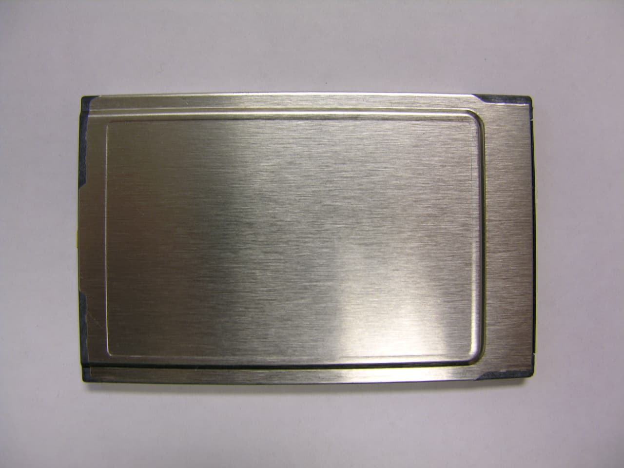
Click to zoom
Application Details
- Equipment Class
- TNB - Licensed Non-Broadcast Station Transmitter
- Date of Grant
- Aug 30, 2005
- Application Purpose
- Original Equipment
- Date of Application
- Aug 30, 2005
- Equipment Note
- Broadband Wireless Router
- Frequency Range
- 4950.00000000 - 4965.00000000
- Country
- United States
Documents & Files
Document Text
Text extracted from the exhibit documents filed with the FCC. Open a document above to read the original.
Users Manual
MOTOMESH 4.0 Wireless Modem Card Users Guide August 2005 6881011Y52-O MOTOMESH 1.0 Wireless Modem Card Users Guide 6881011Y52-O August 2005 ii This page intentionally left blank. MOTOMESH 1.0 Wireless Modem Card Users Guide 6881011Y52-O August 2005 iii Copyrights The Motorola products described in this document may include copyrighted Motorola computer programs. Laws in the United States and other countries reserve for Motorola certain exclusive rights for copyrighted computer programs. Accordingly, any copyrighted Motorola computer programs contained in the Motorola products described in this document may not be copied or reproduced in any manner without the express written permission of Motorola. Furthermore, the purchase of Motorola products shall not be deemed to grant either directly or by implication, estoppels or otherwise, any license under the copyrights, patents or patent applications of Motorola, except for the normal nonexclusive, royalty-free license to use that arises by operation of law in the sale of a product. Disclaimer Please note that certain features, facilities and capabilities described in this document may not be applicable to or licensed for use on a particular system, or may be dependent upon the characteristics of a particular mobile subscriber unit or configuration of certain parameters. Please refer to your Motorola contact for further information. Trademarks Motorola, the Motorola logo, and all other trademarks identified as such herein are trademarks of Motorola, Inc. All other product or service names are the property of their respective owners. Copyrights © 2005 Motorola, Inc. All rights reserved. No part of this document may be reproduced, transmitted, stored in a retrieval system, or translated into any language or computer language, in any form or by any means, without the prior written permission of Motorola, Inc. MOTOMESH 1.0 Wireless Modem Card Users Guide 6881011Y52-O August 2005 iv This page intentionally left blank. 6881011Y52-O August 2005 v Table of Contents Contents ............................................. . . . . Chapter 1: Introduction ........................................................................................... 1-1 General System Requirements .............................................................................................................................. 1-1 Windows XP Minimum System Requirements................................................................................................ 1-1 Windows 2000 Minimum System Requirements............................................................................................. 1-1 What’s in the Box............................................................................................................................................. 1-2 External Connections and LED Indicators ..................................................................................................................... 1-2 Chapter 2: Software Installation............................................................................. 2-1 Installing MOTOMESH Client Software on Windows XP .................................................................................. 2-1 Installing MOTOMESH Client Software on Windows 2000 ............................................................................... 2-7 Chapter 3: Wireless Modem Card Installation....................................................... 3-1 Prerequisite Installation Information .................................................................................................................... 3-1 Working with the Antenna.................................................................................................................................... 3-1 Connecting the Antenna Assembly .................................................................................................................. 3-1 Disconnecting a Pigtail Antenna Assembly ..................................................................................................... 3-2 Connecting the Magnetic Antenna Assembly (Optional)................................................................................. 3-3 Handling the WMC6300 and the WMC7300 ....................................................................................................... 3-4 Installing the Wireless Modem Card................................................................................................................ 3-4 Removing the Wireless Modem Card ............................................................................................................ 3-10 Chapter 4: MeshTray ............................................................................................... 4-1 MeshTray System Tray Icon Status ...................................................................................................................... 4-1 Starting MeshTray............................................................................................................................................ 4-2 MeshTray Tab Contents........................................................................................................................................ 4-2 Status Tab......................................................................................................................................................... 4-1 Configuration Tab ............................................................................................................................................ 4-2 Geographic Position....................................................................................................................................................... 4-3 Geographic Reporting............................................................................................................................................... 4-3 Control Channel Configuration............................…
Text truncated - open the document above for the full version.
Cover Letter(s)
Dated 8/31/05 Federal Communications Commissions Subject: Modular Approval for PCMCIA Card; FCC ID: QJEWMC73000705 Dear Application Examiner, Motorola, WMC7300 PCMCIA Card, is seeking FCC authorization as a part 90 licensed modular transmitter approval. The requirements of the FCC public notice DA 00-1407 are met. The following requirements are fulfilled. 1. The modular transmitter must have its own RF shielding. The radio portion of this module is contained its own RF shielding. Please see photos provided with application. 2. The modular transmitter must have buffered modulation/data inputs. The module has buffered data inputs, buffers are integrated in chip MN2064 referred to as U3 in the schematics. 3. The modular transmitter must have its own power supply regulation. The module incorporates voltage regulation for all voltages used within the module. These are referenced as: U27 - TPS62005DGS U31 – ADP3338-2.85 4. The modular transmitter must comply with the antenna requirements of Section 15.203 and 15.204(c). The module meets the antenna requirements, the device has a unique MMCX antenna connector. 5. The modular transmitter must be tested in a stand-alone configuration. The module was tested in a stand-alone configuration. Please see the test setup photos in the test report. 6. The modular transmitter must be labeled with its own FCC ID number. The module is labeled with its own FCC ID number. Please see label design and label location submitted with application. 7. The modular transmitter must comply with any specific rule or operating requirements applicable to the transmitter and the manufacturer must provide adequate instructions along with the module to explain any such requirements. The module is compliant with all applicable FCC rules. Detail instructions are given in the Users Guide Manual submitted with application. 8. The modular transmitter must comply with any applicable RF exposure requirements. The module in compliant with all RF exposure requirements, please see MPE calculation provided with the application. Sincerely, Jeff Schmidt Motorola, Inc
Operational Description
Motorola, Inc. P.O. Box 948133 Maitland, Florida 32794-8133 U.S.A. 407-659-5300 • Fax 407-659-5301 www.motorola.com/mesh MOTOMESH, Mesh Enabled Architecture, MEA, MeshManager and Multi-Hopping are trademarks or registered trademarks of Motorola, Inc. MOTOROLA and the Stylized M Logo are registered in the U.S. Patent and Trademark Office. All other product or service names are the property of their registered owners. © Motorola, Inc. 2005 R3-40-2005A Over 65 Years of Understanding the Needs of Public Safety In today’s world, you need a solutions provider that understands what Mission Critical is all about: the lives and well-being of your employees and the citizens they protect. That’s why Motorola is a leading provider of interoperable communication systems for public safety, first responders and government agencies. Our experience, along with our skills, people, partnerships and alliances, allow us to build innovative, fully integrated technologies that let organizations like yours share vital information with ease and confidence. We’ve been doing it for 65 years, and we’ll be standing by our customers for years to come. We are committed to bringing all of our knowledge and technical expertise together, so you can focus on what you do best... to serve and protect the public. MOTOMESH The Multi-Radio Broadband Solution for Public Safety, Public Works and Public Access MOTOMESH NETWORK COMPONENTS IAP7300 / Intelligent Access Point The Intelligent Access point provides the wireless gateway between a MOTOMESH network and the wired world. If greater network capacity is required, additional IAPs can be easily deployed. The self-forming, self-healing and self-balancing routing inherent in a MOTOMESH network minimizes the need for expensive site planning. Dual independent backhaul connections keep Mission Critical bandwidth secure and separate from the public network. MWR7300 / Mesh Wireless Router The Mesh Wireless Router extends coverage and connectivity by meshing IAPs and users together. Data signals can hop through one or more MWRs to enable non-line-of-sight communications. MWRs also act as reference points for position location determination. WMC7300 & WMC6300 / Wireless Modem Card 4.9 GHz and 2.4GHz MEA wireless access cards allow any computing device that supports PC cards to access a MOTOMESH network. These cards also form instant broadband meshes between themselves and other MEA client devices when no MOTOMESH infrastructure is present. VMM7300 & VMM6300 / Vehicle Mounted Modem 4.9 GHz and 2.4GHz MEA wireless modems provide a mobile, high bandwidth radio, and feature a standard RJ-45 Ethernet port to support laptops, hubs, printers, IP video cameras or any other Ethernet-ready device. The VMM also forms an instant broadband mesh with any other MEA device. MeshManager / Network Management MeshManager provides a single, comprehensive network management suite for controlling security policies, network provisioning, client administration and performance monitoring for all of the devices in a MOTOMESH network. Motorola’s mesh networking technology enables users to wirelessly access critical broadband applications seamlessly – any time, and anywhere. Licensed 4.9GHz and Unlicensed 2.4GHz Every MOTOMESH access point contains two standards compliant 802.11 (Wi-Fi) radios and two of Motorola’s acclaimed Mesh Enabled Architecture (MEA) mobile broadband radios. One set of Wi-Fi and MEA radios operate in the unlicensed 2.4GHz band. The other operates in the 4.9GHz public safety band. Public Safety, Public Works and Public Access MOTOMESH is a wide area, multi-radio solution that offers the security, capacity and flexibility cities need. It can deliver mobile broadband access to diverse municipal agencies, as well as Wi-Fi access to the public. The MOTOMESH architecture supports up to four radio networks in a single access point and is built on Motorola’s proven MEA mobile broadband networking technology. State of the Art Mesh Networking By leveraging technology originally developed for battlefield communications, MOTOMESH supports high-speed data, video, and position location services for fixed and mobile users. Data links automatically self-form and self-heal between users and network infrastructure. Because every access point is meshed, backhaul, deployment and operational costs are greatly reduced. Municipalities of all sizes may realize a higher ROI than with traditional networks. With the MOTOMESH Multi-Radio Broadband Solution, Municipalities Can Now... Enhance Public Safety by giving First Responders secure and dedicated 4.9GHz mobile broadband connectivity to databases, reports, and video. Boost Municipal Worker efficiency by delivering photos, blueprints and GIS enhanced data to field personnel, while supporting on-line report filing from their vehicles and laptops. Provide residents and visitors with Wi-Fi access in local hotspots, public transportation, or across the entire city. Seamless Mobility – Even at High Speeds Seamless broadband data connectivity is available throughout the network to both stationary and mobile MEA users. This constant connectivity can be used to deliver real-time, remote monitoring of in-vehicle video – even when traveling in excess of 150 mph. Form Instant Tactical Data Networks The Multi-Hopping capabilities of the MEA network allow client devices to form instant, ad hoc broadband networks where no predeployed infrastructure exists. Each MEA radio acts as a router/ repeater for all other MEA devices in the network. MEA users can “hop” through neighboring devices to communicate with each other – or to reach distant network access points that can connect them to other data and voice networks. Fast and Accurate Position Location Depending on network configuration, patented position location technology is available to every MEA device. Using this technology, users know where they are and can instantly find out where any other user is, without having to rely on…
Text truncated - open the document above for the full version.
Operational Description
MPE Calculation for WMC7300 RF Exposure Requirements: §90.1217, §1.1307(b)(1) and §1.1307(b)(2): Systems operating under the provisions of this section shall be operated in a manner that ensures that the public is not exposed to radio frequency energy levels in excess of the Commission’s guidelines. RF Radiation Exposure Limit: §1.1310: As specified in this section, the Maximum Permissible Exposure (MPE) Limit shall be used to evaluate the environmental impact of human exposure to radiofrequency (RF) radiation as specified in Sec. 1.1307(b), except in the case of portable devices which shall be evaluated according to the provisions of Sec. 2.1093 of this chapter. MPE Limit Calculation: EUT’s operating frequencies @ 4950 - 4965 MHz; conducted power = 26.06 dBm (peak) therefore, Limit for Uncontrolled exposure: 1 mW/cm 2 or 10 W/m 2 EUT maximum antenna gain = 11 dBi. Equation from page 18 of OET 65, Edition 97-01 S = PG / 4πR 2 or R = vPG / 4πS where, S = Power Density (10 W/m 2 ) P = Power Input to antenna (0.4036 Watts) G = Antenna Gain (12.589) R = distance to the center of radiation of the antenna (in meter) R = v0.4036W*12.589dB / 4*3.14*(10 W/m 2 ) = v5.0809 / 125.6637 = 0.201 meter The distance between the human body and the RF antenna should not be less than 0.201 m or 20.1 cm.
Operational Description
By simply inserting the Wireless Modem Card (WMC), 6 Mbps burst data rates for streaming audio and video, fast and accurate position location, and voice services can be added to devices with a PCMCIA card slot. Motorola’s Mesh Enabled Architecture (MEA) technology enables the WMC7300 to act as a wireless router/repeater in a MOTOMESH mobile broadband network, increasing network robustness and coverage at no additional cost. Users can instantly form Multi-Hopping, ad hoc, peer-to-peer, broadband networks with or without predeployed network infrastructure. Motorola’s mesh networking technology enables users to wirelessly access critical broadband applications seamlessly – any time, and anywhere. Whether utilizing predeployed infrastructure, or an instant, ad hoc, broadband network formed with other users, Motorola’s mesh networking technology delivers real-time data to detect, prevent, respond. Broadband Designed for Public Safety The WMC7300 operates in the 4.9GHz band that is licensed exclusively for public safety use. This band is free from civilian interference and usage, maximizing the bandwidth and accessibility available to first responders. For users and agencies unaffiliated with public safety, Motorola offers the WMC6300, which operates in the unlicensed, 2.4GHz band. Both Wireless Modem Card versions offer the same, outstanding combination of throughput, mobility and connectivity that first responders need. Robust Data Rates for Mobile Broadband The WMC7300 delivers up to 6 Mbps burst data rates on both the uplink and downlink for voice, video and data. Connectivity can be available for Internet, live streaming video, databases, telemetry, and other high bandwidth applications – even at speeds in excess of 150 mph. End-to-End Industry Standard IP Support MOTOMESH supports end-to-end, standards based Internet Protocol (IP). Any IP based application or IP capable device will work seamlessly within a MOTOMESH network, including FIPS-140-2 compliant VPNs. Create Peer-to-Peer Networks Anywhere Client devices with Wireless Modem Cards can form their own peer-to-peer network – any time, and anywhere. A high speed, broadband network will automatically form between authorized devices – even in places where there is no network infrastructure. Users can effortlessly establish separate, private group communications. Position Location and Navigation Services The Wireless Modem Card offers position location capabilities without relying on costly Global Positioning Systems (GPS). Depending on network configuration, location determination can be quicker and more accurate than consumer GPS, and is available in places GPS is limited, such as parking garages and urban canyons. Motorola provides location data in a standard GPS format, allowing applications that operate with GPS data to interact seamlessly with the WMC7300. Over-the-Air (OTA) Network Management Every MOTOMESH device can be managed remotely using MeshManager software. End-to- end IP support enables IT managers to download and update client software – or add new features and services – wirelessly, greatly simplifying software maintenance procedures. WMC7300 Wireless Modem Card • for MOTOMESH The WMC7300 enables 4.9GHz MOTOMESH users to wirelessly access broadband applications and create mobile ad-hoc networks. Motorola, Inc. P.O. Box 948133 • Maitland, Florida 32794-8133 U.S.A. www.motorola.com/mesh • 407-659-5300 • Fax 407-659-5301 MOTOMESH, Mesh Enabled Architecture, MEA, MeshManager, MeshTray and Multi-Hopping are trademarks or registered trademarks of Motorola, Inc. MOTOROLA and the Stylized M Logo are registered in the U.S. Patent and Trademark Office. All other product or service names are the property of their registered owners. © Motorola, Inc. 2005 MOTOMESH Additional Network Features • Advanced Encryption Standard (AES) Support for Wi-Fi Clients • Layer 2 Multicast Support • Network Time Protocol (NTP) support • Differentiated Services using IP Quality of Service (QoS) Support • Over-the-Air Software Upgrade Support • MAC Access Control lists • Web (HTTP) based management interface • SNMP agent for remote management • Telnet interface with command-line management • Firmware Upgrades via Trivial File Transfer Protocol (TFTP) WMC7300 RADIO CHARACTERISTICS Output Power 24 dBm RF Modulation QDMA Operating Frequency (GHz) 4.950 - 4.965 Maximum Burst Data Rate 6 Mbps Spectrum Used 20MHz Antenna Type Omnidirectional, 3.6 dBi Antenna Connector MMCX Host Interface PCMCIA DEVICE DRIVER Client Software MeshTray and MeshView Supported Operating Systems Windows 2000, Windows XP and PocketPC 2002 NETWORK Network Managament Software MeshManager via SNMP Network Architecture Peer-to-Peer Multi-Hopping SECURITY Virtual Private Network (VPN) Support for FIPS-140-2 compliant encryption (Padcom, RadioIP and NetMotion) Authentication 802.1X (Infrastructure/Client and Client/Client) POWER Power Consumption (Transmit) 3.3W Power Consumption (Receive) 2.0W PHYSICAL Dimensions 3.37" x 2.126" x 0.19" (8.6cm x 5.4cm x 0.5cm) Weight 1.13 oz (30.8g) Packaging Standard PCMCIA form factor LED Indicators Transmit and receive ENVIRONMENTAL Temperature Range -35 to 55 °C Humidity 0 to 90%, non-condensing Certifications FCC Part 15 & 90, UL, CSA AVAILABLE OPTIONS Antenna Magnetic mount antenna for vehicles available R3-14-2040
Parts List/Tune Up Info
FCC ID: QJEWMC73000705 Applicant: Motorola Inc.- Mesh Networks Product Group 731 Confirmation Number: TC664735 The tune-up procedure over power range or at specific operating levels is not applicable for this unit. One hundred percent of all radios are factory calibrated to insure compliance with specifications; therefore, no Users tuning is required.
Parts List/Tune Up Info
Item Quantity Reference Description Part Numbe r Manufacturer 1 2 C137, C139 X-Case; Tant.Cap.; 100uF. 10V, +/-20%. TAJX107M010R AVX. 2 55 C13,C20,C21,C22,C23,C24, 0402; Cap.; 0.1uF, X5R, 10V, +/-10%. X5R0402ATTD104K KOA Speer. C25,C26,C27,C28,C29,C30,C31,C32,C33,C34,C35,C36,C38,C39,C40,C41,C42,C43,C44,C45,C46,C48,C49,C52,C56,C59,C60,C61,C62,C63, C65,C67,C72, C75,C77,C79,C84,C107, C108,C118,C119,C124,C127,C131 C138, C144,C145,C146,C147 3 12 C14,C55,C58,C99,C113,C129 0402; Cap.; 0.01uF, X7R, 50V, +/-10%. X7R0402ATTD103K KOA Speer. C148,C153,C154,C161,C170,C188 4 2 C15,C197 0402; Cap.; 1000pF, X7R, 50V, +/-10%. X7R0402ATTD102K KOA Speer. 5 9 C9,C47,C64,C91,C155,C158 P-Case;Tant.Cap.; 10uF. 6.0V, +/-10%. TAJR106K006R AVX. C162,C169,C179 6 2 C51,C50 0402; Cap.; 47pF, NPO, 50V, +/-2%. 04025A470GAT2A AVX. 7 2 C57,C53 0402; Cap.; 82pF, NPO, 50V, +/-2%. 04025A820GAT2A AVX. 9 3 C163,C181,C183 0402; Cap.; 2.2pF, NPO, 50V, +/-5%. 04025A2R2BAT2A AVX. 11 2 C109,C115 0402; Cap.; 12pF, NPO, 50V, +/-2%. 04025A120GAT2A AVX. 12 3 C184,C185,C187 0402; Cap.; 0.5pF, NPO, 50V, +/- .1pF. 04025A0R5BAT2A AVX. 13 1 C94 0402; Cap.; 2200pF, X7R, 50V, +/-10%. X7R0402ATTD222K KOA Speer. 14 10 C95,C140,C150,C152,C157 0402; Cap.; 100pF, NPO, 50V, +/-5%. 04025A101JAT2A AVX. CC160,C175,C178,C192,C196 15 3 C96,C101,C174 0402; Cap.; 1.5pF, NPO, 50V, +/- .1pF. 04025A1R5BAT2A AVX. 16 11 C165,C167,C168,C171, 0402; Cap.; 10pF, NPO, 50V, +/-2%. 04025A100GAT2A AVX. C176,C177,C180 C189,C193,C194,C195 20 1 J1 MMCX SMT Connector (Preferred). 262107 Connex. 21 1 J2 PCMCIA 68-Pin Connector. 146229-1 Amp. 22 1 J3 DNP 23 1 J4 DNP 24 6 L4,L11,L12,L13,L14,L15 0603; W/W Ind.; 1.8uH, +/- 5%. CTML0603-1R8J Inductors Inc. 25 0 0402; M/L Ind.; 2.2nH, +/- .3nH LL1005-FHL2N2S TOKO. 26 13 L7,R85,R125,R128,R129 DNP R132,R133,C149,C151,C156,C159 C166,C172 27 4 L21,L22,C186,L18 0402; M/L Ind.; 1.0nH, +/- .3nH TFL05101N0 Garrett Electric 28 1 L16 10uH Power Inductor, 20%. LPO1704-103M CoilCraft. 29 1 L19 0402; M/L Ind.; 1.8nH, +/- .3nH LL1005-FHL1N8S TOKO. 30 6 R14,R32,R33,R122,R123,148 0402; Res.; 49.9K Ohm, 1/16 W., 1%. RK73H1ELTP4992F KOA Speer. 31 18 R17,R18,R19,R20,R21,R22, 0402; Res.; 10K Ohm, 1/16 W., 1%. RK73H1ELTP1002F KOA Speer. R27,R28,R29,R30,R31, R34,R35,R36,R37,R38,R111,R149 32 13 R23,R39,R40,R61,R62,R92,R93 0402; Res.; 1.0K Ohm, 1/16 W., 1%. RK73H1ELTP1001F KOA Speer. R118,R119,R120,R121,R146 R118,R119,R120,R121 33 6 R24,R25,R41,R42,R45,R46 0402; Res.; 205 Ohm, 1/16 W., 1%. RK73H1ELTP2050F KOA Speer. 36 12 R49,R55,R63,R64,R65,R71,R90 0402; Res.; 100 Ohm, 1/16 W., 1%. RK73H1ELTP1000F KOA Speer. R135,R136,R137,R138,R139 37 2 R50,R96 0402; Res.; 12K Ohm, 1/16 W., 1%. RK73H1ELTP1202F KOA Speer. 38 2 R68,R56 0402; Res.; 4.02K Ohm, 1/16 W., 1%. RK73H1ELTP4021F KOA Speer. 41 3 R87,R124,R147 0402; Jumper; 0 Ohm, 1 Amp C.C. RK73Z1ELTP KOA Speer. 42 1 R140 0402; Res.; 10.0 Ohm, 1/16 W., 1%. RK73H1ELTP10R0F KOA Speer. 48 1 R110 0402; Res.; 470K Ohm, 1/16 W., 1%. RK73H1ELTP4703F KOA Speer. 49 1 U3 Black Widow ASIC MN2064. MB87M3220PBT-G Mesh Networks 50 1 U4 Processor Supervisor IC. TPS-3838E18DBVR Texas Instruments. 51 1 U5 Processor Supervisor IC. TPS-3823-30DBVT Texas Instruments. 52 1 U6 Multi-Chip Module w/ Flash / SRAM. S71JL064HA0BAW010 Spansion 55 1 U9 7nsec, 2.7 Volt Comparartor. LMV7219M5 National Semi. 56 1 U10 Mixed-Signal Front-End Processor. AD9861BCP-50 Analog Devices. 59 1 U14 4.9Ghz. Zero-IF Transceiver IC. MAX2828ETN Maxim. 62 2 U20,U34 5.5Ghz. RF BandPass Filter. 5515BP15C975 Johanson. 63 1 U18 5.5Ghz. RF Balun. 5400BL15B100 Johanson. 64 1 U37 3V PA Driver Amplifier. STA-5063 Sirenza. 65 1 U22 Low Voltage SPST Analog Switch. MAX4715EXK-T Maxim. 66 2 U25,U26 Differental Amplifier LT6600CS8-20 Linear Tech 67 1 U27 1.8 VDC Switchmode Regulator TPS62005DGS Texas Instruments. 68 1 U28 2.85 VDC LDO Regulator ADP3338AKC-2.85 Analog Devices. 69 1 U29 Dual Tri-state buffer 74LVC2G126DCTR Texas Instruments. 71 1 XO1 VCTCXO; 5x3mm, 16.0 Mhz. +/-2.5ppm. ASVTX-09-16.0 Abracon Corp. 72 1 XO2 VCTCXO; 5x3mm, 20.0 Mhz. +/-2.5ppm. ASVTX-09-20.0 Abracon Corp. 73 1 D1 Green Right Angle LED. LTST-S270GKT Lite-On Electronics. 74 1 D2 Red / Orange Right Angle LED. LTST-S270EKT Lite-On Electronics. 75 1 PCB PCMCIA PCB Fab. And Drilled. PWB HMM000012 Tyco. 76 1 Case Type II PCMCIA Enclosure. PC-B5068L00272 Duel. 77 1 Light pipe Light Pipe Assembly. MS50064A Duel. 80 2 Q5,Q6 DMMT 3906W DMMT 3906WDICT 82 9 R112,R113,R114,R115,R141 0402; Res.; 49.9 Ohm, 1/16 W., 1%. RK73H1ELTP49R9F KOA Speer. R127,R130,R131,R134 84 1 R89 0402; Res.; 1.82K Ohm, 1/16 W., 1%. RK73H1ELTP1821F KOA Speer. 85 1 U31 D Flip-Flop SN74LVC2G74DCTR Texas Instruments. 86 1 C164 0402; Cap.; 1.0pF, NPO, 50V, +/-5%. 04025A1R0BAT2A AVX. 87 2 R95,R145 0402; Res.; 681 Ohm, 1/16 W., 1%. RK73H1ELTP6810F KOA Speer. 88 0 0402; Res.; 4,99K Ohm, 1/16 W., 1%. RK73H1ELTP4991F KOA Speer. 89 1 R142 0402; Res.; 100K Ohm, 1/16 W., 1%. RK73H1ELTP1003F KOA Speer. 90 1 R143 0402; Res.; 150 Ohm, 1/16 W., 1%. RK73H1ELTP1500F KOA Speer. 91 1 R144 0402; Res.; 348 Ohm, 1/16 W., 1%. RK73H1ELTP3480F KOA Speer. 92 1 U33 PHEMT GaAs IC 0.5-6Ghz. LNA. MGA-665P8 Agilent. 93 1 U35 SPDT PHEMT GaAs IC RF Switch. AS225-313 Skyworks. 94 1 U36 3V, 4.9Ghz. Linear Power Amplifier. LX5506BLQ Microsemi. 95 1 U38 MAX II PLD EPM570T100C4 Altera 96 1 C104 0402; Cap.; 150pF, NPO, 50V, +/-5%. 04025A151JAT2A AVX. 97 1 R94 0402; Res.; 680 Ohm, 1/16 W., 1%. RK73H1ELTP6800F KOA Speer. 27 1 L20 0402; M/L Ind.; 1.2nH, +/- .3nH TFL05101N2 Garrett Electric
Test Report
MET Laboratories, Inc. Safety Certification - EMI - Telecom Environmental Simulation 33439 WESTERN AVENUE ! UNION CITY, CALIFORNIA 94587 ! PHONE (510) 489-6300 ! FAX (510) 489-6372 DOC-EMC700 7/9/04 Electromagnetic Compatibility Criteria Test Report For the Motorola, Inc. 4.9 GHz WMC7300 PCMCIA Card Tested under The FCC Verification Rules Contained in Title 47 of the CFR, Part 90, Subpart Y for Private Land Mobile Radio Services MET Report: EMCS17444A-FCC90 August 8, 2005 Prepared For: Motorola, Inc. 485 N. Keller Rd., Ste. 250 Maitland, FL 32751 Prepared By: MET Laboratories, Inc. 33439 Western Ave. Union City, California 94587 Motorola, Inc. Electromagnetic Compatibility 4.9 GHz WMC7300 PCMCIA Card CFR Title 47, Part 90, Subpart Y MET Report: EMCS17444A-FCC90 © 2005, MET Laboratories, Inc. Page ii of vi DOC-EMC700 7/9/04 Electromagnetic Compatibility Criteria Test Report For the Motorola, Inc. 4.9 GHz WMC7300 PCMCIA Card Tested under The FCC Verification Rules Contained in Title 47 of the CFR, Part 90, Subpart Y for Private Land Mobile Radio Services MET Report: EMCS17444A-FCC90 Kerwinn Corpuz, Project Engineer Cheryl Anicete Electromagnetic Compatibility Lab Documentation Department Engineering Statement: The measurements shown in this report were made in accordance with the procedures indicated, and the emissions from this equipment were found to be within the limits applicable. I assume full responsibility for the accuracy and completeness of these measurements, and for the qualifications of all persons taking them. It is further stated that upon the basis of the measurements made, the equipment tested is / is not capable of operation in accordance with the requirements of Part 90, Subpart Y of the FCC Rules under normal use and maintenance. Tony Permsombut, Manager Electromagnetic Compatibility Lab Electromagnetic Compatibility Motorola, Inc. Report Status Sheet 4.9 GHz WMC7300 PCMCIA Card CFR Title 47, Part 90, Subpart Y MET Report: EMCS17444A-FCC90 © 2005, MET Laboratories, Inc. Page iii of vi DOC-EMC700 7/9/04 Report Status Sheet Revision Report Date Reason for Revision ∅ August 8, 2005 Initial Issue. Electromagnetic Compatibility Motorola, Inc. Table of Contents 4.9 GHz WMC7300 PCMCIA Card CFR Title 47, Part 90, Subpart Y MET Report: EMCS17444A-FCC90 © 2005, MET Laboratories, Inc. Page iv of vi DOC-EMC700 7/9/04 Table of Contents 1. Testing Summary ........................................................................................................................................................ 1 2. Equipment Configuration........................................................................................................................................... 2 2.1. Overview................................................................................................................................................................ 2 2.2. Test Site ................................................................................................................................................................. 3 2.3. Description of Test Sample .................................................................................................................................... 3 2.4. Equipment Configuration..........................................................................................................…
Text truncated - open the document above for the full version.
Contact Information
Applicant
Qianlin Zhou(Regulatory Specialist)
Test Firm
MET Laboratories, Inc.Robert Frier
Technical Specifications
| # | Rule Parts | Frequency Range | Power Output | Emission | Tolerance |
|---|---|---|---|---|---|
| 1 | 90 | 4.95 GHz - 4.96 GHz | 404.00 mW | 17M2F1D | 46000.0000000000 Hz |
Other Applications from Zebra Technologies Corporation
QJEAP716101
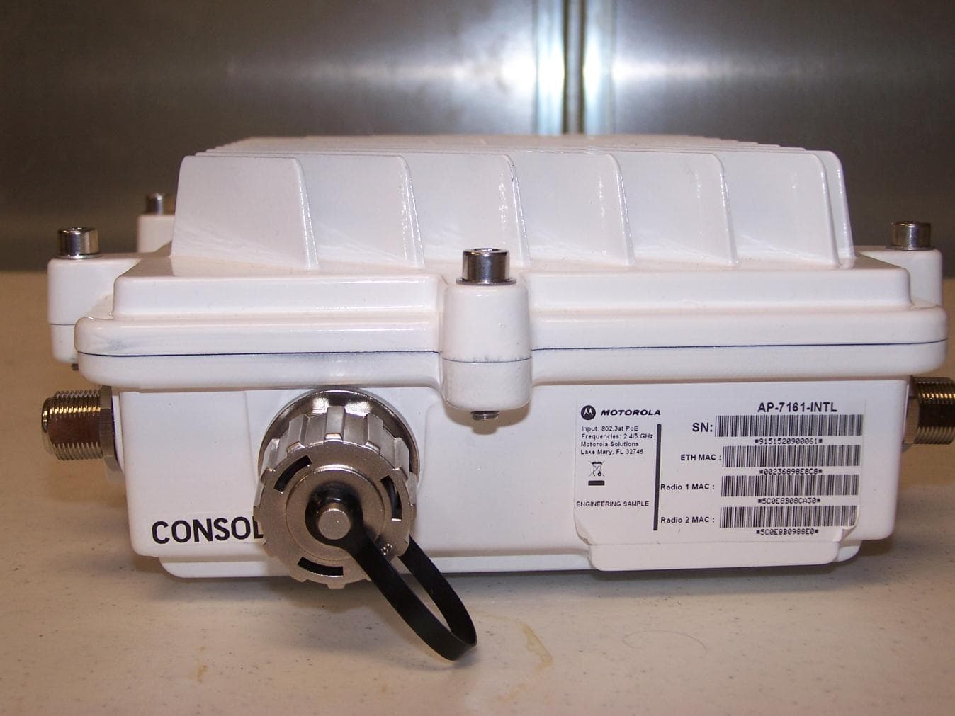
Aug 08, 2011Mesh AP-7161 Outdoor Wireless Access Point
Equipment Class
TNB - Licensed Non-Broadcast Station Transmitter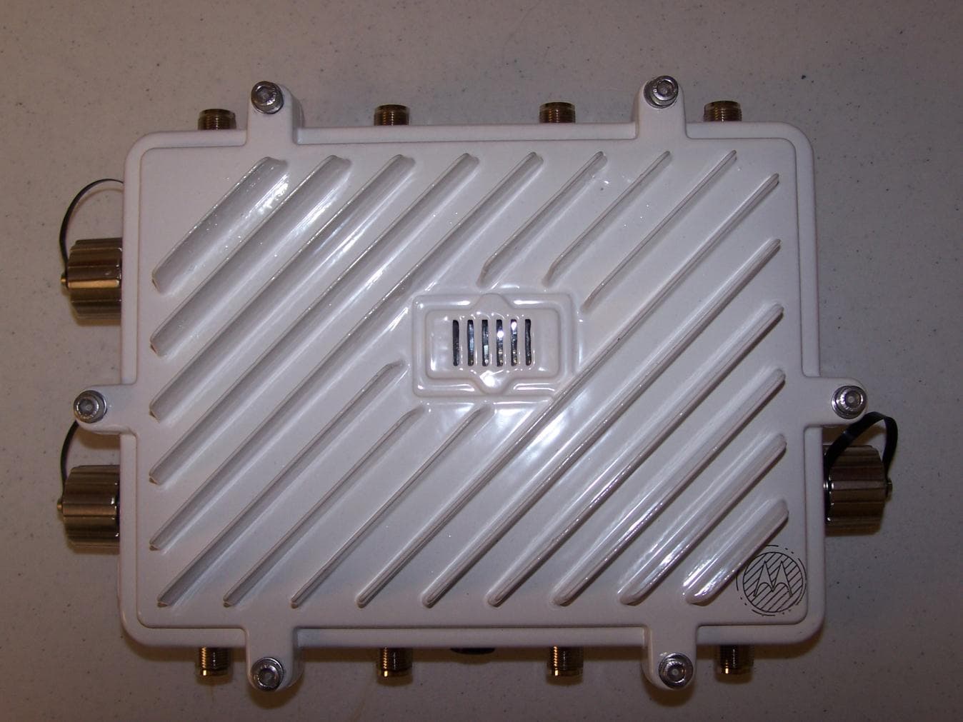
QJEAP716102
Aug 02, 2011Mesh AP-7161 Outdoor Wireless Access Point
Equipment Class
NII - Unlicensed National Information Infrastructure TX
QJEMM718101
Mar 29, 2010Mesh AP-7181 Outdoor Wireless Access Point
Equipment Class
DTS - Digital Transmission System
QJE-MM4300-5800
Nov 13, 2007MM Duo 4300-5800 is an infrastructure device
Equipment Class
DTS - Digital Transmission System
QJE-MM-4300-49
May 29, 2007Dual 802.11a/b/g 2.4GHz 4.9GHz Meshing Radio
Equipment Class
TNB - Licensed Non-Broadcast Station Transmitter