QJSMV140LCD Monitor
Megavision co., Ltd.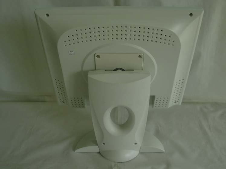
Click to zoom
Application Details
- Equipment Class
- JBP - Part 15 Class B Computing Device Peripheral
- Date of Grant
- Jun 08, 2003
- Application Purpose
- Original Equipment
- Date of Application
- Jun 08, 2003
- Equipment Note
- LCD Monitor
- Company
- Megavision co., Ltd.
- Country
- South Korea
Documents & Files
Document Text
Text extracted from the exhibit documents filed with the FCC. Open a document above to read the original.
Users Manual
1 MEGAVISION SYSTEM. Inc 3003 MOTH FIRST STREET SUIT #331 SAN JOSE, CA 95134 TEL : 408-432-5052 FAX : 408-232-5440 TOLL FREE : 080-854-5447 e-mail : [email protected] www.megavisionsys.com 2 TABLE OF CONTENTS FCC COMPLIANCE STATEMENT NOTE 3 ADJUSTING YOUR LCD MONITOR -------------- • General safety precautions ..................................... 4 • Unpacking your monitor ....................................... 7 • Viewing angle ...................................................... 8 • Connecting your monitor ....................................... 9 • User controls ...................................................... 10 • OSD Functions and adjustments ................................. 11 • Menu adjustments ................................................ 12 • Refining the picture ............................................. 14 APPENDIX ----------------------------------- - • Power management function ................................... 15 • Video input terminal .............................................. 16 • Display modes .................................................... 17 • Troubleshooting ................................................... 18 • Option (Pivot function) .......................................... 20 • Specifications ................................................... 21 3 FCC COMPLIANCE STATEMENT * NOTE : This equipment has been tested and found to comply with the limits for a Class B digital device, pursuant to part 15 of the FCC Rules. These limits are designed to provide reasonable protection against harmful interference in a residential installation. This equipment generates, uses and can radiate radio frequency energy and, if not installed and used in accordance with the instructions, may cause harmful interference to radio communications. However, there is no guarantee that interference will not occur in a particular installation. If this equipment does cause harmful interference to radio or television reception, which can be determined by turning the equipment off and on, the user is encouraged to try to correct the interference by one or more of the following measures: • Reorient or relocate the receiving antenna. • Increase the separation between the equipment and receiver. • Connect the equipment into an outlet on a circuit different from that to which the receiver is connected. • Consult the dealer or an experienced radio/TV technician for help. Modifications not expressly approved by the manufacturer could void the user's authority to operated the equipment under FCC rules. 4 General safety precautions This Monitor has been engineered and manufactured to assure your safety. Please read this manual and comply with the warnings and the procedures to avoid any serious electrical shock and other serious damage . 1. 2. 3. 4. Do not place anything heavy, wet or magnetic on the monitor or power cord. Do not cover the ventilation openings nor touch them with metallic or flammable material. High temperature can cause troubles. Avoid operating the monitor in extreme heat, humidity or dusty areas. Extreme temperature may cause discoloration or dama ges. Ambient Temperature : 0°C ~ 40°C Do not use a solvent, such as benzene, to clean the monitor to prevent any damages to the LCD surface. Do not use fine tools such as a pin or a pencil near the monitor to prevent any scratch to the LCD surface. 5 5. 6. 7. 8. Place the monitor on a flat surface to prevent it from falling. Do not apply any mechanical shocks to the machine. Install it in a well-ventilated area or secure enough space for ventilation. Turn the monitor off before connecting it to the power outlet. 6 CAUTION : RISK OF ELECTRIC SHOCK, DO NOT OPEN 9. 10. 11. Make sure that the power cord and the other cords are properly connected. Overloaded AC outlets and extension cords are dangerous. Also, the frayed power cords and the broken plugs may cause electric shock or fire. Do not open the monitor. There are no user-serviceable components inside. There is a risk of exposure to high-voltage electricity inside, even when power is turned off. If the display monitor does not operate properly, unplug the power cord and contact your dealer. Handling the electrical equipment carelessly will cause a serious electrical shock and other hazards. 7 Unpacking your monitor Please make sure the following items are included with your monitor. If you find that any of these items are missing or appear damaged, contact your dealer immediately. The power cord can be different depending upon different voltage areas. 8 Viewing angle Your monitor was designed to allow you to adjust it to a comfortable viewing angle. The viewing angle can be adjusted 5° to 30° forward and backward respectively as indicated by the arrow marks below. 5° 30° 9 Connecting your monitor Be sure to turn the computer off before connecting the monitor g Connect the video signal cable (15Pin connector) to the system’s 15 pin D-sub connector which is located on the back panel of the computer. g Connect the power adaptor cord to the monitor and then to the power supply. g After powering on the computer, adjust the display using the various controls provided. For further information on the installation procedure, please refer to the operating guide of the computer being used. 10 User controls Front control buttons LED MENU ADJUST DOWN UP SELECT POWER No. Key name Description 1 MENU Opens the OSD menu. 2 ADJUST Activates the auto adjustment function. 3 SELECT Selects the main menu items and sub- menu items. 4 ▲ Moves to the upper menu item or sub- menu item. Increases the value of the parameter. 5 ▼ Moves to the lower menu item or sub- menu item. Decreases the value of the parameter. 6 POWER Turns on/off the monitor. 7 LED Indicates the status of the monitor. • Green : Normal operation. • Blinking : Power saving mode or disconnected signal cable. 11 OSD Function and adjustment Main menu and control selection Press the MENU key to access the main m…
Text truncated - open the document above for the full version.
Block Diagram
MV140 BLOCK DIAGRAM 14.318MHz L CD P A N E L D-SUB Myson DIGITAL R.G.B SCALER R.G.B LVDS (ANALOG PC INPUT) (MTL005F) TRANSMITTER H.VSYNC DDC BUFFER MCU ON/OFF CONTROL I N V E R T E R SDA.SCL ( MTV230MS ) OSD/POWER/LCDCONTROL 12MHz O S D & POWER DC- DC / DC 12V 80ARD JACK CONVERTER 5V 3.3V
External Photos
E E M M C C T T E E S S T T R R E E P P O O R R T T Report reference No: KST-EMC030025 KOSTEC Co.,Ltd. 180-254,Annyung-Ri, Taean-Yup, Hwasung-shi, Kyunggi-do, Korea Tel : +82-31-222-4251 Fax: +82-31-222-4252 http://www.kosteclab.com Page : 15 of 15 MAY 21, 2003 EUT Front Rear
ID Label/Location Info
TFT LCD MONITOR Made in Korea Model No: MV140 Power : AC110-240V 12V DC / 3.3A (Adapter) FCC ID: QJSMV140 Manufactured by Megavision Co., Ltd. CAUTION II Read User’s Manual before using. Do not attempt to service the monitor by yourself. Contact the authorized service center. THIS DEVICE COMPLIES WITH PART 15 OF THE FCC RULES. OPERATION IS SUBJECT TO THE FOLLOWING TWO CONDITIONS: (1) THIS DEVICE MAY NOT CAUSE HARMFUL INTERFERENCE, AND (2) THIS DEVICE MUST ACCEPT ANY INTERFERENCE RECEIVED, INCLUDING INTERFERENCE THAT MAY CAUSE UNDESIRED OPERATION.
ID Label/Location Info
E E M M C C T T E E S S T T R R E E P P O O R R T T Report reference No: KST-EMC030025 KOSTEC Co.,Ltd. 180-254,Annyung-Ri, Taean-Yup, Hwasung-shi, Kyunggi-do, Korea Tel : +82-31-222-4251 Fax: +82-31-222-4252 http://www.kosteclab.com Page : 21 of 21 MAY 21, 2003 Appendix – Sample Label Location TFT LCD MONITOR Made in Korea Model No: MV140 Power : AC110-240V 12V DC / 3.3A (Adapter) FCC ID: QJSMV140 Manufactured by Megavision Co., Ltd. CAUTION II Read User’s Manual before using. Do not attempt to service the monitor by yourself. Contact the authorized service center . THIS DEVICE COMPLIES WITH PART 15 OF THE FCC RULES. OPERATION IS SUBJECT TO THE FOLLOWING TWO CONDITIONS: (1) THIS DEVICE MAY NOT CAUSE HARMFUL INTERFERENCE, AND (2) THIS DEVICE MUST ACCEPT ANY INTERFERENCE RECEIVED, INCLUDING INTERFERENCE THAT MAY CAUSE UNDESIRED OPERATION.
Internal Photos
E E M M C C T T E E S S T T R R E E P P O O R R T T Report reference No: KST-EMC030025 KOSTEC Co.,Ltd. 180-254,Annyung-Ri, Taean-Yup, Hwasung-shi, Kyunggi-do, Korea Tel : +82-31-222-4251 Fax: +82-31-222-4252 http://www.kosteclab.com Page : 16 of 16 MAY 21, 2003 Inside AC/DC adapter E E M M C C T T E E S S T T R R E E P P O O R R T T Report reference No: KST-EMC030025 KOSTEC Co.,Ltd. 180-254,Annyung-Ri, Taean-Yup, Hwasung-shi, Kyunggi-do, Korea Tel : +82-31-222-4251 Fax: +82-31-222-4252 http://www.kosteclab.com Page : 17 of 17 MAY 21, 2003 Inverter board (Front) Inverter board (Rear) E E M M C C T T E E S S T T R R E E P P O O R R T T Report reference No: KST-EMC030025 KOSTEC Co.,Ltd. 180-254,Annyung-Ri, Taean-Yup, Hwasung-shi, Kyunggi-do, Korea Tel : +82-31-222-4251 Fax: +82-31-222-4252 http://www.kosteclab.com Page : 18 of 18 MAY 21, 2003 AD Board ( Front ) AD Board ( Rear ) E E M M C C T T E E S S T T R R E E P P O O R R T T Report reference No: KST-EMC030025 KOSTEC Co.,Ltd. 180-254,Annyung-Ri, Taean-Yup, Hwasung-shi, Kyunggi-do, Korea Tel : +82-31-222-4251 Fax: +82-31-222-4252 http://www.kosteclab.com Page : 19 of 19 MAY 21, 2003 OSD Board ( Front ) OSD Board ( Rear ) E E M M C C T T E E S S T T R R E E P P O O R R T T Report reference No: KST-EMC030025 KOSTEC Co.,Ltd. 180-254,Annyung-Ri, Taean-Yup, Hwasung-shi, Kyunggi-do, Korea Tel : +82-31-222-4251 Fax: +82-31-222-4252 http://www.kosteclab.com Page : 20 of 20 MAY 21, 2003 LCD Panel none
Test Report
E E M M C C T T E E S S T T R R E E P P O O R R T T FCC EVALUATION REPORT FOR CERTIFICATION EMC TEST REPORT KOREA Standard Technology Test report No.: KST-EMC030025 Manufacturer’s Name : Megavision Co., Ltd. Manufacturer’s Address: 799 Anyang Megavalley,Room 504 Kwangyang-Dong , Dongan-Gu, Anyang-Shi, Kyunggi-Do , KOREA EUT’s: FCC ID : QJSMV140 Product Name : LCD Monitor Model Number(s) : MV140 Product Options : N/A Category : FCC Part 15 sub. part B Class B Digital Device Supplementary Information The device bearing the brand name and FCC ID specified above has been shown to comply with the applicable technical standards as indicated in the measurement report and was tested in accordance with measurement procedures specified in ANSI C63.4-1992 . I attest to the accuracy of data and all measurements reported herein were performed by or were made under my supervision and are correct to the best of my knowledge and belief. I assume full responsibility for the completeness of these measurements and vouch for the qualifications of all persons taking them. Date: May 21, 2003 Te s t e d b y : Approved by: Kim, Ha-HyoungLee, Woen-Woo E E M M C C T T E E S S T T R R E E P P O O R R T T Contents 1. Description of Device 2. Test Facility 3. MAP 4. Test system configuration 5. Description of E.U.T. 6. Summary of test results. 7. Test results. 8. Photographs. Appendix. Sample Label E E M M C C T T E E S S T T R R E E P P O O R R T T Report reference No: KST-EMC030025 KOSTEC Co.,Ltd. 180-254,Annyung-Ri, Taean-Yup, Hwasung-shi, Kyunggi-do, Korea Tel : +82-31-222-4251 Fax: +82-31-222-4252 http://www.kosteclab.com Page : 3 of 21 MAY 21, 2003 1. Description of Device 1) Kind of equipment: LCD Monitor 2) FCC ID: QJSMV140 3) Model Name: MV140 4) Serial No.: None 5) Type of Sample Tested: Pre-production 6) High Frequency Used: 14.318MHz 12.000MHz 7) Adapter Model name: LSE0107A1240 Manufacturer: LI SHIN INTERNATIONAL ENTERPRISE CORP. Serial no: A20312134913 8) Power Rating: 1phase AC100-240V, 0.8A, 50/60Hz Output: DC 12V, 3.3A 9) Tested Power supply: 1phase AC120V, 60Hz 10) Date of Manufacture: May 20, 2003 11) Manufacture: Megavision Co., Ltd 12) Description of Operating: Scroll All “H” Character Resolution 1024*768 Vertical Frequency: 75Hz 13) Dates of Test: May 20, 2003 14) Place of Tests: Korea Standard Technology EMC site 15) Test Report No: KST-EMC030025 E E M M C C T T E E S S T T R R E E P P O O R R T T Report reference No: KST-EMC030025 KOSTEC Co.,Ltd. 180-254,Annyung-Ri, Taean-Yup, Hwasung-shi, Kyunggi-do, Korea Tel : +82-31-222-4251 Fax: +82-31-222-4252 http://www.kosteclab.com Page : 4 of 21 MAY 21, 2003 2. Test Facility The open field test site and conducted measurement facility are used for these testing, where are located following address and drawing. This site was fully described in a report dated November 14, 2002, that was submitted to the FCC. Korea Standard Technology ( KOSTEC Co., Ltd) Head office: 302 City Bild, 1600-3 Kwanyang-dong, Dongan-gu, Anyang-shi, Kyunggi-do, Korea Telephone No : 82-31-388-2051 Facsimile No: 82-31-388-2052 Test Lab :180-254, Annyung-Ri, Taean-Yup, Hwasung-shi, Kyunggi-do, Korea Telephone No : 82-31-222-4251 Facsimile No: 82-31-222-4252 MIC(Ministry of Information and Communication) No: KR0042 FCC Filing No. : 525762 VCCI Membership Number : 2005 E E M M C C T T E E S S T T R R E E P P O O R R T T Report reference No: KST-EMC030025 KOSTEC Co.,Ltd. 180-254,Annyung-Ri, Taean-Yup, Hwasung-shi, Kyunggi-do, Korea Tel : +82-31-222-4251 Fax: +82-31-222-4252 http://www.kosteclab.com Page : 5 of 21 MAY 21, 2003 3. MAP Korea Hwasung-shi (open area test site) KOSTEC Co., Ltd E E M M C C T T E E S S T T R R E E P P O O R R T T Report reference No: KST-EMC030025 KOSTEC Co.,Ltd. 180-254,Annyung-Ri, Taean-Yup, Hwasung-shi, Kyunggi-do, Korea Tel : +82-31-222-4251 Fax: +82-31-222-4252 http://www.kosteclab.com Page : 6 of 21 MAY 21, 2003 4. TEST SYSTEM CONFIGURATION Operation Environment Ambient Temperature ( °C ) Humidity ( % ) Pressure ( hPa ) 10m Open Area site 22.1 51 1008 Shielded room: 20 50 1007 Test site These testing were performed following locations ; Shielded room : Conducted Emission, 10m Open Area Site: Radiated Emission Measurement Uncertainty All measurements involve certain levels of uncertainties, especially in field of EMC. The factors contributing to uncertainties are test receiver, Cable loss, antenna factor calibration, Antenna directivity, antenna factor variation with height, antenna phase center variation, antenna frequency interpolation, measurement distance variation, ite imperfection, mismatch, and system repeatability. Based on NIS 80,81, The measurement uncertainty level with a 95% confidence level were applied. sample calculation Conducted emission The field strength is calculated by adding the LISN factor, cable loss from the measured reading. The sample calculation is as follows: FS = MR + LF + CL MR = Meter Reading LF = LISN Factor CL = Cable Loss If MR is 30dB, LISN Factor 1dB, CL 1dB The result (MR) is 30 + 1 + 1 = 32dBuV E E M M C C T T E E S S T T R R E E P P O O R R T T Report reference No: KST-EMC030025 KOSTEC Co.,Ltd. 180-254,Annyung-Ri, Taean-Yup, Hwasung-shi, Kyunggi-do, Korea Tel : +82-31-222-4251 Fax: +82-31-222-4252 http://www.kosteclab.com Page : 7 of 21 MAY 21, 2003 5. Description of E.U.T. Product Description Manufactured By: Megavision Co.,Ltd. Address: 799 Anyang Megavalley,Room 504 Kwangyang-Dong , Dongan-Gu, Anyang-Shi, Kyunggi-Do , KOREA Model: MV140 Serial Number: None ConfigUration of EUT Description Manufacturer Model/Part #Serial Number LCD Panel Hyundai HT14X14-201 40T013201SL200044 AD Board None NLX05M S030301401 Inverter Board None AT0104HD(BF) None Ac/dc adapter LI SHIN INTERNATIONAL ENTERPRISE CORP. LSE0107A1240 A20312134913 EUT Used cables Cable Type Shield Length (m) FerriteConnector Connection Point 1 Connection Point 2 POWER Line No 1.0 - DC INLET Ac/dc adapter Main power source VGA In Yes 1.5 yes D-sub EUT Pers…
Text truncated - open the document above for the full version.
Test Setup Photos
E E M M C C T T E E S S T T R R E E P P O O R R T T Report reference No: KST-EMC030025 KOSTEC Co.,Ltd. 180-254,Annyung-Ri, Taean-Yup, Hwasung-shi, Kyunggi-do, Korea Tel : +82-31-222-4251 Fax: +82-31-222-4252 http://www.kosteclab.com Page : 13 of 21 MAY 21, 2003 8.PHOTOGRAPHS Conducted emission ( Front ) Conducted emission ( Rear ) E E M M C C T T E E S S T T R R E E P P O O R R T T Report reference No: KST-EMC030025 KOSTEC Co.,Ltd. 180-254,Annyung-Ri, Taean-Yup, Hwasung-shi, Kyunggi-do, Korea Tel : +82-31-222-4251 Fax: +82-31-222-4252 http://www.kosteclab.com Page : 14 of 21 MAY 21, 2003 Radiated Emission ( Front ) Radiated Emission ( Rear )
Contact Information
Applicant
Kim Tai Hyun(Lab Member)
Test Firm
KOSTEC Co., Ltd.Cho Jae-Beom
Technical Specifications
| # | Rule Parts | Frequency Range | Power Output |
|---|---|---|---|
| 1 | 15B | - | - |
Other Applications from Megavision co., Ltd.

QJSMV220HB
Jul 22, 2007TFT LCD MONITOR
Equipment Class
JBP - Part 15 Class B Computing Device Peripheral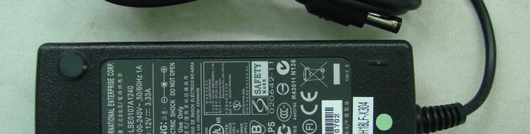
QJSMV192SN
May 03, 2007TFT LCD MONITOR
Equipment Class
JBP - Part 15 Class B Computing Device Peripheral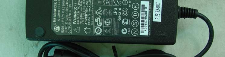
QJSMV191SN
May 03, 2007TFT LCD MONITOR
Equipment Class
JBP - Part 15 Class B Computing Device Peripheral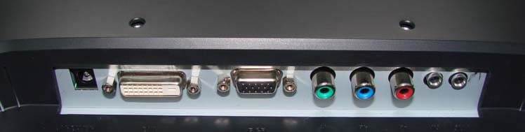
QJSMV220FB
Jan 22, 2007TFT LCD Monitor
Equipment Class
JBP - Part 15 Class B Computing Device Peripheral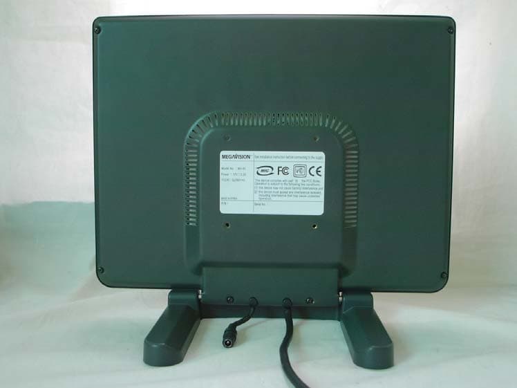
QJSMV141
May 19, 2004lcd monitor
Equipment Class
JBP - Part 15 Class B Computing Device Peripheral