QKK-C02Radar Detector
Rocky Mountain Radar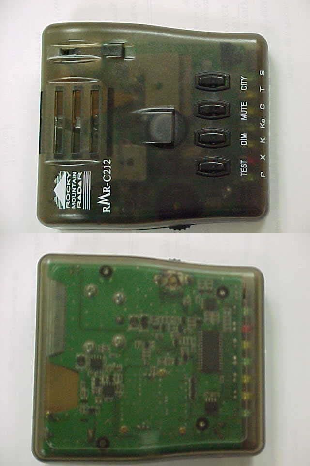
Click to zoom
Application Details
- Equipment Class
- CRD - Part 15 Radar Detector
- Date of Grant
- Oct 20, 2002
- Application Purpose
- Original Equipment
- Date of Application
- Oct 20, 2002
- Equipment Note
- Radar Detector
- Frequency Range
- 33400.00000000 - 36000.00000000
- Company
- Rocky Mountain Radar
- Country
- United States
Documents & Files
Document Text
Text extracted from the exhibit documents filed with the FCC. Open a document above to read the original.
Users Manual
Photographs for Radiated Emissions
Users Manual
RMR-C410 Radar and Laser Detector Owners Manual SPECIFICATIONS: Radar & Laser Detector: Frequencies: 10.525 GHz 24.125 GHz 33-36 GHz 904 Nano-meter Sensitivity: X-112 Dbm K-110 Dbm Ka-wide-102 Dbm Laser < .5 microwatt Alarm: Separate for each Band Variable alarm for Range Controls: Volume, On/Off, Dim, Mute, City/Highway, Test VG-2: Automatic Frequency Shift Size: 1.4” x 3.0” x 4.4” The RMR-C410 detector is a full-featured radar and laser detector. The radar detector is a dual conversion scanning superheterodyne receiver with separate alarms for each of the radar bands, dim function, city/highway and mute select. It detects front and rear laser and radar. Other: One-Year Ticket Rebate Program Three-Year Warranty FCCID: QKK-C02 This product has been designed and certified to comply with Part 15 of the FCC Rules. Any changes or modifications not expressly approved by Rocky Mountain Radar may void your authority to use this product. Operation is subject to the following two conditions: (1) this device may not cause harmful interference, and (2) this device must accept any interference received, including interference that may cause undesired operation. 2 Installation: 1) Attach the windshield bracket to the C410 detector. Align the edge on the bracket with the slot opening on the front of the case. Slide the bracket into the case until it locks into place. 2) Place the windshield bracket in the upper center portion of the windshield. The ideal position will be right below the rear view mirror. Press firmly to seat the suction cups. Note: Tinted glass may degrade the laser performance. 3) Bend the windshield bracket mount to a level position. 4) The RMR-C410 will hang from the bottom of the bracket and must have an unobstructed view of the road ahead. 5) Insert the small end of the power cord gently into the power jack on the right side of the unit and the large end into the cigarette lighter receptacle. Remote mounting is not recommended. Hard wire: Remove cigarette lighter plug. Connect the black with white stripe wire to +12 Volts, and then connect the solid black wire to ground. 3 CONTROLS: There are 4 buttons on top of the C410, Test, Dim, Mute and City. Dim: Press the Dim button for one second to dim the alarm lights. There are 3 levels of brightness. To brighten the alarm lights press the dim button again. Mute: Press the Mute button for one second to disable the alarm speaker for quiet operation. To reactivate the alarm speaker press the Mute button again for one second. City: Press the City button for one second to reduce false alarms in high RF noise areas. The yellow City light will illuminate to show activation. Test: Press and hold the test button for any length of time to perform a manual test. When pressed you will hear a soft chirping sound and the yellow light will come on. Reminder! The C410 will memorize the settings of the features above when the unit is powered off. Be sure to readjust the settings to your normal preferences. Power and Volume: Power is provided through the thumb wheel switch on the left side of the unit. Rotate the wheel forward to turn on and increase the volume for the alarm. 4 Alarms: A separate alert tone will sound for each band of Radar encountered with a different colored light, (Ka-Green), (K-Yellow), (X-Red) illuminated. Tone frequency will increase as signal strength becomes stronger. (Fig. A) All alarm lights will flash when Laser is detected. (Fig. B) VG-2: VG-2 detection is indicated with a separate alarm along with the green power light blinking. VG- 2 will make you undetectable to radar. (Fig. C) Diagnostics: The RMR-C410 has a full internal automatic diagnostic system. If the power light goes off and remains off, check the 2-amp fuse in the power cord by unscrewing the silver tip and removing the fuse. If the fuse is good (wire inside the fuse unbroken), return the unit for service. Rocky Mountain Radar does not condone the use of excessive speed on the highways, nor does it endorse breaking the speed limit laws of the United States of America. Please drive safely when using this or any other electronic product in your car. 5 Selectable VG-2: To activate VG-2 detection turn the unit on. After the self-test has completed, press and hold the Mute button down for 3~5 seconds until the unit beeps three times. VG-2 detection is now activated. To deactivate press and hold the Mute button for 3~5 seconds until the unit buzzes once. VG-2 is now off . Auto Memory: The RMR-C410 has an automatic memory. Any settings enabled when the unit is turned off will still be enabled when the unit is turned back on. If you have set the unit on Mute or have dimmed the alarm lights be sure to readjust the settings to your normal preference. Fig. A 6 Warranty The RMR-C410 is guaranteed against defects in workmanship and materials for 36 months from the date of purchase. Should any malfunction occur, the unit would be repaired or replaced by the factory at no charge. You may have your unit checked free of charge at the factory during this warranty period. Returns should be sent freight prepaid with an explanation of the problem, your physical address (no PO Boxes) and telephone number. Send to: ROCKY MOUNTAIN RADAR 6469 Doniphan Drive El Paso TX 79932 Phone: 915-587-0307 Fax: 915-587-6408 We do not accept COD shipments We do not accept freight collect shipments Accessories The following accessories and parts are available: Windshield mount $ 5.00 Suction Cups (set of 3) $ 2.00 2 amp fuses (two each) $ 2.00 Power Cord $ 5.00 Replacement Owners Manual $ 3.50 Set of Colored Bezel Panels (6) $10.00 Set of Da-Glo Bezel Panels (3) $10.00 A $10.00 shipping and handling fee will be added to the total of each order. VISA/MC and Discover Accepted Tamper Fee Tampering with, disassembly, or modification of this product voids the warranty and a tamper fee of $150.00 will be charged to repair it. 7 Manufactured Exclusively by Rocky Mountain Radar in the USA
ID Label/Location Info
FCC ID. QKK-C02 410-222222 This device complies with Part 15 of the FCC Rules. Operation is subject to the following two conditions: (1) this device may not cause harmful interference, and (2) this device must accept any interference received, including interference that may cause undesired operation. Rocky Mountain Radar
Operational Description
Operating Description The RMR-C410 radar detector is a dual conversion scanning super-heterodyne receiver with separate alarms for each of the radar bands, dim function, city/highway and mute select. It detects front and rear laser and radar. The RMR-C410 has selectable VG-2, allowing the driver to select whether he wishes to scan for the presence of detector-detectors or not. The RMR-C410 is completely VG-2 undetectable. The RMR-C410 is built with high reliability surface mount construction and VCO technology for improved performance over a wide operating temperature. The RMR- C410 detects all radar and laser bands used by law enforcement: 10,475 – to – 10,575 MHz, 24,050 – to – 24,250 MHz, and 33,400 – to – 36,000 MHz, as well as 904 nanometer infrared signals. The RMR-C410 is compact, designed exclusively for automotive use and is powered by the 12-Volt electrical system in a car or truck.
RF Exposure Info
RF EXPOSURE The RMR-C410 radar detector is a dual conversion scanning super-heterodyne receiver. The RMR-C410 detects all radar bands used by law enforcement: 10,475 – to – 10,575 MHz, 24,050 – to – 24,250 MHz, and 33,400 – to – 36,000 MHz. The RMR-C410 is designed exclusively for automotive use and is powered by the 12- Volt electrical system in a car or truck.
Schematics
5 5 4 4 3 3 2 2 1 1 DD CC BB AA A 1 / 5 RMR-C212 2002. 1. 22 Front_End DESCRIPTION REVISIONS APPDATA ATTOWAVE MODEL : TITLE : DATE :REV. APPR. CHECK DRAW SHEET C7 1u R4 10k Q1 FET C9 100P Q3 FET C8 100P R1 100 ANT_horn ANT1 R2 100 R6 180 Q2 HBFP420 C3 100P D1 V.D. C2 100n R5 30 C5 0.3P L1 1.8nH R11 4.7K J2 3P pin R3 270 C4 2P C6 100P R7 180 R9 4.7KR10 4.7K R8 0 J1 3P pin C1 100P IF_OUT +8V V_TUNE V_TUNE IF_OUT +8V RMR-C410 NOTES: = PRINTED CIRCUIT ELEMENTS 5 5 4 4 3 3 2 2 1 1 DD CC BB AA APP IF Circuit DATA REVISIONS 2 / 5 2002 . 01 .22A DESCRIPTION P (47) P (8) Euroonly (1.5P) Air Coil 600MHz(350MHz)1350MHz(1450MHz)2100MHz(2200MHz) **( )¥¬ EURO RMR-C212 P (5) (0.3-0.9-4TL) ATTOWAVE MODEL : TITLE : DATE :REV. APPR. CHECK DRAW SHEET TP1 or TP4 TP2 +8V +8V +5V_RF +8V +8V J4 3P pin R26 180 C37 7P R38 220 C35 100n C46 1P C24 12p L2 1.8uH R36 680 C12 100P Q10 KRC107S R34 7.5K FB2 FB1608 J3 3P pin R28 5.1K Q7 2SC4228 C18 470p FB1 FB1608 C30 10n R20 47 R19 3.3K R31 5.1K C32 NC C34 10P R30 7.5K R25 100 C29 NC C26 100p R33 7.5K C55 1P U1 TK 14584 123654 121110 987 C11 100n R29 5.1K C56 8P Q5 2SC4228 C41 100P C45 5P L5 4.1nH C20 220P Q6 2SC4228 C17 1P C47 5P R24 180 L4 1.8uH C50 1P Q4 HBFP420 C54 2P C52 100n C19 100n R35 7.5K R23 4.7K C27 12P R15 51K R21 180 C13 10P C40 100n C42 100P (L9)1 (8.2nH) C51 100P U2 uPC8112 1 2 3 5 6 4 RF IN GND LOCAL VCC IF OUT PS C22 1n Q9 KRC107S L3 8.2nH C23 100p R22 0 C53 2P R32 7.5K R16 620 R39 270 C44 1P C16 10n C14 10n C38 100P C57 2P L6 22nH C49 6P R12 3.3K C21 1n R18 0 C25 100P C48 2P R37 7.5K C31 10n R13 22K C15 100n C33 NC C10 NC C43 100P C28 100P R27 180 R17 39K C58 2P L7 10.5nH C39 100P Q8 KRC107S R14 680 C36 100n IF_IN -Vgs DEMOD LO_SEL_1LO_SEL_3 V_TUNE LO_SEL_2 IF_IN +8V RSSI RMR-C410 5 5 4 4 3 3 2 2 1 1 DD CC BB AA REVISIONS APPDATADESCRIPTION 2002. 01. 22 RMR-C212 A Jammer & Buzzer Circuit 3 / 5 ATTOWAVE MODEL : TITLE : DATE :REV. APPR. CHECK DRAW SHEET TP9 TP10 +5V +12V +12V R71 330 C100 100p VR1 5KB Q19 2N2907 R69 330 R66 4.7K R68 10 D4 S1G 12 D5 JAMMER PWR Q11 2N2222 Q18 2N2222 C63 NC R63 4.7K R150 220 R49 2K Q13 2N2222 Q16 2N2907 Q15 2N2222 NC 10K R62 4.7K R44 470 R57 2K C105 33p BAV70 12 R40 51 (1/2W) Q20 KTC3876Y R58 2K R53 330 R65 1k C64 1u BZ1 Buzzer + R146 2K R47 300 D6 JAMMER TEST Q14 2N2222 R59 2K C106 33p D7 12 D2 LD R73 18 U4 74HC02 1 2 3 4 5 6 7 9 10 11 12 13 14 8 1 2 3 4 5 6 7 9 10 11 12 13 14 8 SW1 SLIDE-1C3P R46 1.5M R52 4.7K C61 10n Q17 2N2222 C59 10n R72 680 C60 10UF R70 18 R45 30 R145 30 Q12 2N2222 R50 4.7K X1 8MHz R43 470 D7 12 D8 BAV70 12 R67 4.7K R42 220 R48 4.7K R55 1K R60 150 R56 2K R61 4.7K D3 LD R51 4.7K R64 10k U3 csc-002 1 2 3 4 5 6 7 89 10 11 12 13 14 15 16 1 2 3 4 5 6 7 89 10 11 12 13 14 15 16 C62 220P SOUND JAMMER JAMMER ANTDARK DIM DARKDIM CLK_OUT JAMMER_ON Clock & Buzzer Circuit Clock & Buzzer Circuit RMR-C410 IN SOUND ANT OUT ANT 5 5 4 4 3 3 2 2 1 1 DD CC BB AA SHIELDED A 4 / 5 RMR-C212 2002. 01. 22 Laser / V_Tune REVISIONS 2012/X7R/16V DATAAPPDESCRIPTION ATTOWAVE MODEL : TITLE : DATE :REV. APPR. CHECK DRAW SHEET TP6 TP3 TP8 TP7 TP5 +5V +5V +5V +5V +5V +8V +5V +8V +5V +8V +5V+5V R91 150k R97 330K Q25 KTC3880Y R118 27K R103 18K C87 1n C80 100n R78 220K R100 220K R94 220K R116 330K C77 18n R99 100K R89 18K Q26 KTC3880Y C68 18n C84 5p R98 4.7k C71 100n - + U6A 5 6 7 8 4 R115 47K R80 470K R96 10K C81 1n - + U5A LM358 3 2 1 Q21 2N2222 C72 0.15uF R109 27K R79 47K R75 220K R86 10K R113 2.2M C69 1u R106 10K C74 470p R105 4.7K R77 47K Q24 2N2222 FB3 FB1608 D9 BAT54WS - + U10A LM393 3 2 1 8 4 VR2 100KB R102 10K + C76 10u16V(T) - + U9A LM358 5 6 7 8 4 FB5 FB2012 C75 100n R108 470K C88 100p R88 47K R93 10K R110 2.2M R101 100K R74 27K R95 4.7K D10 BAT54WS R117 2.2M R112 2.2M R81 2.2M R85 100K NC C66 R92 100K D12 BPW34FS R83 330K C82 100n R111 10K R82 470K C67 470p FB4 FB1608 R84 10K R107 47K C79 100n Q23 2N2222 Q22 2N2907 - + U8A LM358 3 2 1 R90 22K 100n C65 - + U7A 5 6 7 R114 100K C85 100p LTR546AD D11 C73 1n C78 100n C83 47p R87 10M C86 100p R104 47K LASER_SIG DEMOD VG2 RD_SIG SWP_PULSE V_TUNE RMR-C410 5 5 4 4 3 3 2 2 1 1 DD CC BB AA PWR X K C Mute Dim City GRN ORG AMB GRN REVISIONS DATAAPPDESCRIPTION 5 / 5 RMR-C212 2002. 01. 22 MCU Circuit A Test Ka ATTOWAVE MODEL : TITLE : DATE :REV. APPR. CHECK DRAW SHEET +5V +5V_LED +5V +5V+5V +5V_LED +5V_RF +5V +5V +5V +B +8V JAMMER_ON +5V R131 10k R138 4.7K R119 2.2K R140 680 C101 1n R133 4.7K FB6 FB2012 J5 DC_JACK 1 2 U14 78L05 1 23 VIN GNDVOUT R120 4.7K C96 39N C102 1n U15 24C02/SO8 1 2 3 5 6 7 8 4 A0 A1 A2 SDA SCL WP VCC GND SW2 1109S R127 330 SW3 1109S U16A 7S00 2 4 1 5 3 C93 100n SW5 1109S D17LED C90 100n FB7 FB2012 R143 2.2K C105 10n D15LED U12 78L08 1 2 3 VIN GND VOUT Q28 2N2907 FB9 FB2012 D18LED SW4 1109S D13 S1G D14LED + C98 10u16V(T) R122 330 C97 100n C106 100n R139 4.7K C99 100n D19 KDS226 C89 100n R128 470K D16LED C100 10n R126 330 C103 1n C91 100n R135 47K R136 47K R121 330 R130 18 R142 39K R132 100K Q27 2N2222 + C95 10u16V(T) R123 3.3KR124 330 R125 4.7K FB8 FB2012 C104 1n - + U13A LM358 3 2 1 8 4 R134 47K R141 220K R129 100K R137 47K U11 16C72 20 19 9 10 28 23 22 21 8 1 18 17 15 16 14 26 11 13 24 2 25 3 12 7 27 4 5 6 VDD VSS1 OSC1 OSC2 RB7 RB2 RB1 RB0/INT VSS2 MCLR RC7 RC6 RC4 RC5 RC3 RB5 RC0 RC2 RB3 RA0 RB4 RA1 RC1 RA5 RB6 RA2 RA3(AN3) RA4 C94 100n + C92 10u16V(T) RD_SIG SWP_PULSE LASER_SIG CLK_OUT -Vgs LO_SEL_1LO_SEL_2 LO_SEL_3 RSSI VG2 SDA SCL SCL JAMMER DIM DARK SOUND SDA CLK_OUT RMR-C410 ON OFF
Test Report
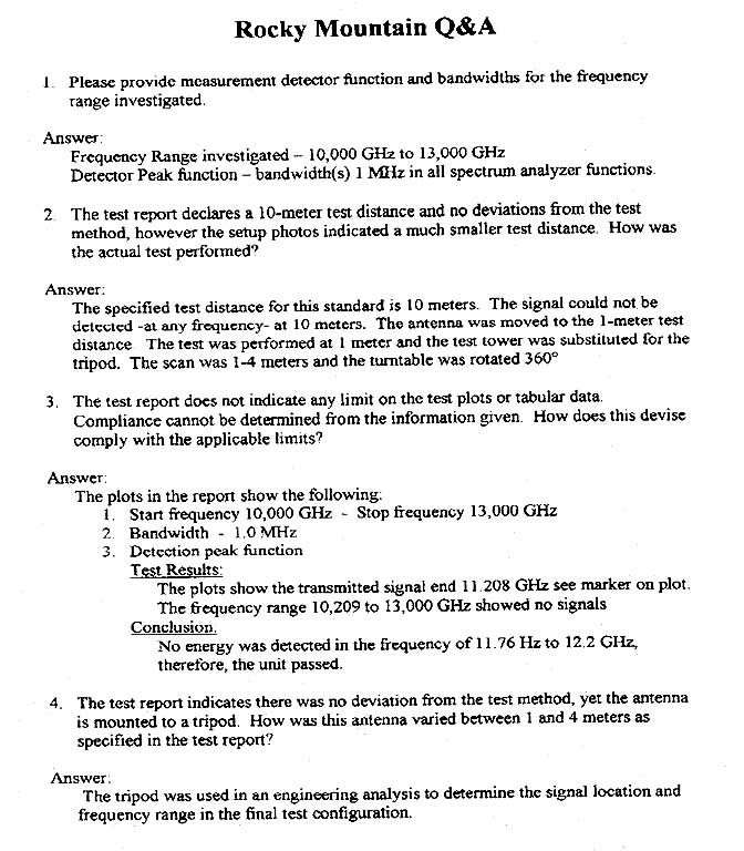
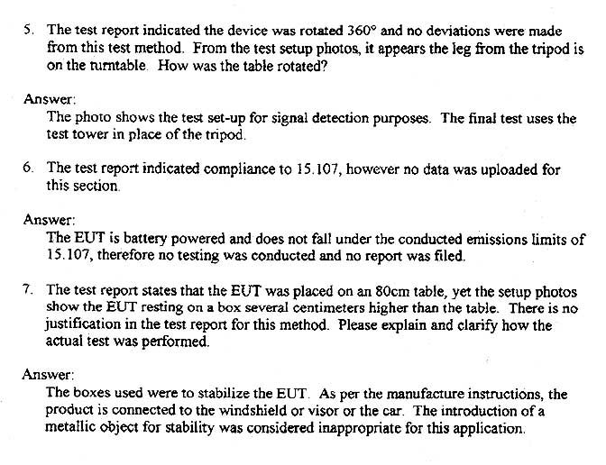
October 25, 2002 Mr. Mike Churchman Rocky Mountain Radar 6469 Doniphan Drive El Paso, TX 79932 Dear Mr. Churchman: Enclosed is the test report for the Rocky Mountain Radar Radar Detector RMR C410 tested at our facility, 556 Route 222 in Groton, New York. This facility is on file with the FCC per CFR 47 2.948 (Site File Number 31040/SIT) and is NVLAP accredited. As narrated in the report, the product configuration meets the requirements of the FCC per CFR 47 Part 15 Class B for Unintentional Radiators. Thank you for selecting Diversified T.E.S.T. Technologies, Inc. for your testing needs. We look forward to working with you on future projects. Should you have any questions, or concerns regarding this report please contact me at (800) 724-6452 or (607) 898-4218. Sincerely, Shaun Hotaling Technical Associate DIVERSIFIED T.E.S.T. TECHNOLOGIES, INC. FCC Part 15 Class B TEST REPORT Rocky Mountain Radar Radar Detector, RMR C410 Project Number: 5487 This report shall not be reproduced, except in full, without the written approval of DTT, Inc. And must not be used to claim product endorsement by NVLAP or any agency of the U.S. Government. 0 T T E E S S T T R R E E P P O O R R T T FCC per CFR 47 Part 15 Class B September 25, 2002 Prepared for: Rocky Mountain Radar by: Diversified TEST Technologies, Inc. DIVERSIFIED T.E.S.T. TECHNOLOGIES, INC. FCC Part 15 Class B TEST REPORT Rocky Mountain Radar Radar Detector, RMR C410 Project Number: 5487 This report shall not be reproduced, except in full, without the written approval of DTT, Inc. And must not be used to claim product endorsement by NVLAP or any agency of the U.S. Government. 1 Table of Contents PRODUCT DESCRIPTION Page 2 TEST SITE INFORMATION Page 3 RADIATED EMISSIONS CALCULATIONS Page 4 RADIATED EMISSIONS TEST PROCEDURE Page 5 DEVIATIONS FROM TEST METHOD Page 5 DIAGRAMS Page 6 PHOTOGRAPHS Page 7 DATA CHARTS Page 8 Sections omitted from your report were not required as per the agreed test plan DIVERSIFIED T.E.S.T. TECHNOLOGIES, INC. FCC Part 15 Class B TEST REPORT Rocky Mountain Radar Radar Detector, RMR C410 Project Number: 5487 This report shall not be reproduced, except in full, without the written approval of DTT, Inc. And must not be used to claim product endorsement by NVLAP or any agency of the U.S. Government. 2 Standard Information & Product Description STANDARD: FCC Part 15 Class B CLIENT: Rocky Mountain Radar 6469 Doniphan Drive El Paso, TX 79932 PRODUCT: Radar Detector Model #: RMR C410 Condition: New PRODUCT RECEIVED: September 23, 2002 TEST DATES: September 23, 2002 PREPARED BY: Diversified TEST Technologies, Inc. 556 Route 222 • PO Box 8 Groton, New York 13073 (607) 898-4218 (607) 898-4830/fax COMPILED BY: Shaun Hotaling Technical Associate REVIEWED BY: Thomas P. Sims President DIVERSIFIED T.E.S.T. TECHNOLOGIES, INC. FCC Part 15 Class B TEST REPORT Rocky Mountain Radar Radar Detector, RMR C410 Project Number: 5487 This report shall not be reproduced, except in full, without the written approval of DTT, Inc. And must not be used to claim product endorsement by NVLAP or any agency of the U.S. Government. 3 Test Site Information Location and Registration: • Open field test site, Diversified T.E.S.T. Technologies, Inc., 556 Rte 222 in Groton NY Radiated Emissions: • 30-meter open field • The equipment under test (EUT) was placed at a 10-meter range in an RF transparent shelter. Calibration: • Calibrated to ANSI Procedure C 63.4-1992 • Copy of calibration on file with FCC per Title CFR 47 Section 2.948. Equipment Calibration: • The test equipment used is calibrated by the manufacturer or independent calibration laboratory. • These test results are traceable to NIST, because all calibrations are traceable to NIST standards. Test Performance: • Federal Communication Commissions (FCC) regulations as outlined in Title CFR 47, Part 15, for Class A Unintentional Radiators. • Test procedures used were to CFR 47 15.31, ANSI C 63.4- 1992. • Radiated Emissions per limits 15.109 • Conducted Emissions per limits 15.107 DIVERSIFIED T.E.S.T. TECHNOLOGIES, INC. FCC Part 15 Class B TEST REPORT Rocky Mountain Radar Radar Detector, RMR C410 Project Number: 5487 This report shall not be reproduced, except in full, without the written approval of DTT, Inc. And must not be used to claim product endorsement by NVLAP or any agency of the U.S. Government. 4 Radiated Emissions Calculations Diversified T.E.S.T. Technologies, Inc. uses automated data reductions to determine product compliance to radiated emissions regulations. The program is fully automated and plots the signal amplitude against the frequency grid to which it was tested. The plotted charts will print out, in tabular form, the maximized frequencies that were near or over the specification limit. The automatic computation takes into account the programmed parameters required by the FCC specifications; i.e., bandwidth, scan speed and the antenna/cable loss and amplifier gain factors. The product's signal data is compared to a current ambient scan. The frequencies that are of significant amplitude are automatically sorted out by the computer and are brought out to be further analyzed and maximized. These same frequencies are also profiled by rotating the product 360 degrees on the EMCO 12-foot turntable. Test Instruments Used 1. 9 Ridge Horn ANT: Electro-Metrics, Model #: RGA 60, Serial # 2981 2. 9 HP Spectrum Analyzer, Model # 8593EM 3. 9 COAX: PIN Style R/G 142-B/V 4. 9 Power Supply: SORENSEN & Co., Inc., Model #: T50-1.5 5. 9 Printer: EPSON LX-810 DIVERSIFIED T.E.S.T. TECHNOLOGIES, INC. FCC Part 15 Class B TEST REPORT Rocky Mountain Radar Radar Detector, RMR C410 Project Number: 5487 This report shall not be reproduced, except in full, without the written approval of DTT, Inc. And must not be used to claim product endorsement by NVLAP or any agency of the U.S. Government. 5 Radiated Emissions Test Procedure The product was tested on our open field range, according to Title CFR 47 15.31, ANSI C 6…
Text truncated - open the document above for the full version.
Test Setup Photos
Photographs for Radiated Emissions
Contact Information
Applicant
Michael B Churchman(President)
Technical Contact
CKC Laboratories, Inc.Mary Ellen Clayton
[email protected]209-966-5240
5473-A Clouds Rest · Mariposa, California · United States
Non-Technical Contact
CKC Laboratories, Inc.Mary Ellen Clayton
[email protected]209-966-5240
Test Firm
Diversified T.E.S.T. TechnologiesThomas Sims
Technical Specifications
| # | Rule Parts | Frequency Range | Power Output |
|---|---|---|---|
| 3 | 15B | 33.40 GHz - 36.00 GHz | - |
Other Applications from Rocky Mountain Radar

QKK-MC1
Apr 18, 2011RADAR DETECTOR
Equipment Class
DSC - Part 15 Security/Remote Control Transmitter
QKK-TRK
Apr 18, 2011RADAR DETECTOR
Equipment Class
CRD - Part 15 Radar Detector
QKK-RD1
Nov 29, 2005Radar Detector
Equipment Class
CRD - Part 15 Radar Detector
QKK-D10
Nov 29, 2005Radar Detector
Equipment Class
CRD - Part 15 Radar Detector
QKK-D04
Mar 29, 2004Radar Laser Detector
Equipment Class
CRD - Part 15 Radar Detector