QKK-D03Radar Detector
Rocky Mountain Radar
Click to zoom
Application Details
- Equipment Class
- CRD - Part 15 Radar Detector
- Date of Grant
- Dec 15, 2002
- Application Purpose
- Original Equipment
- Date of Application
- Dec 15, 2002
- Equipment Note
- Radar Detector
- Frequency Range
- 33400.00000000 - 36000.00000000
- Company
- Rocky Mountain Radar
- Country
- United States
Documents & Files
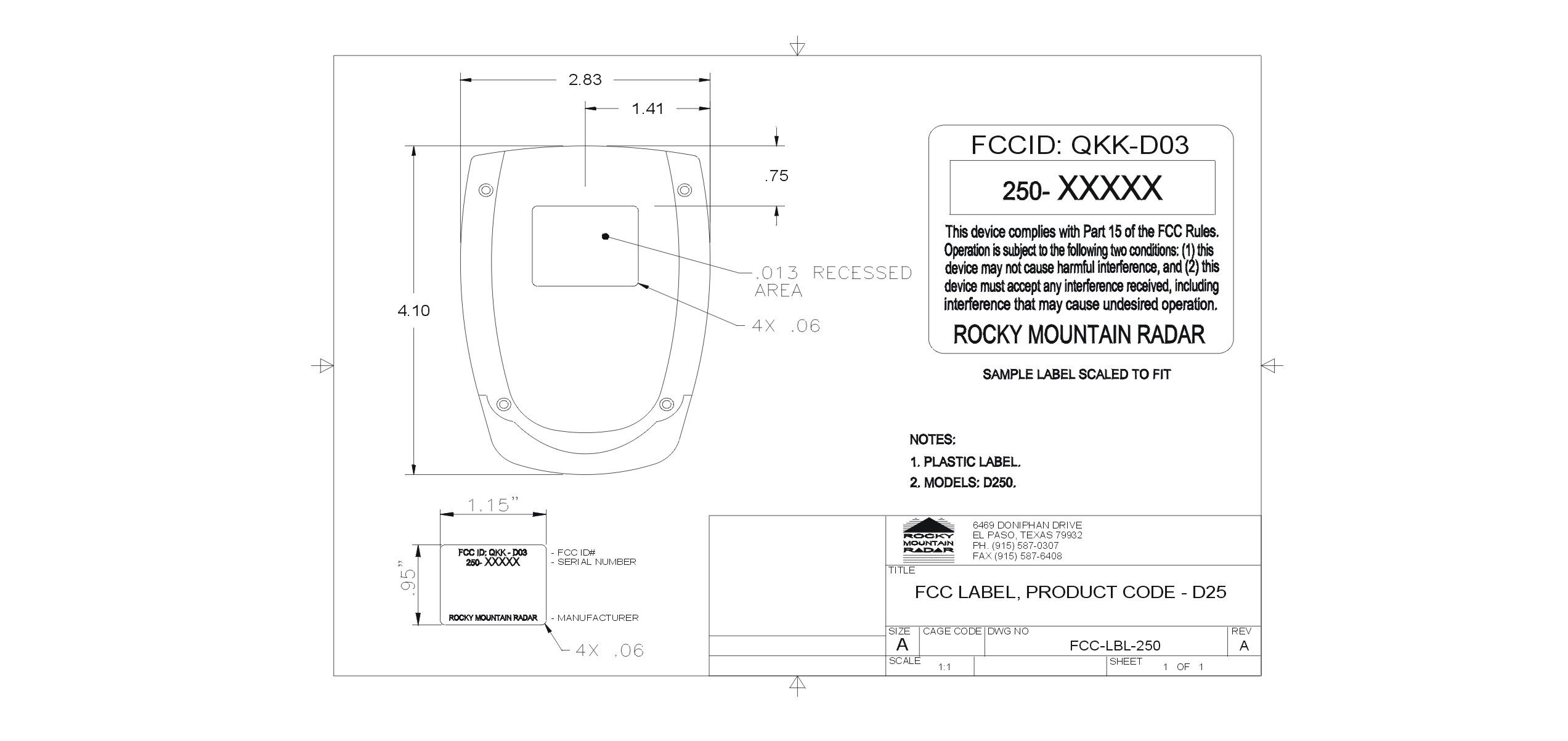
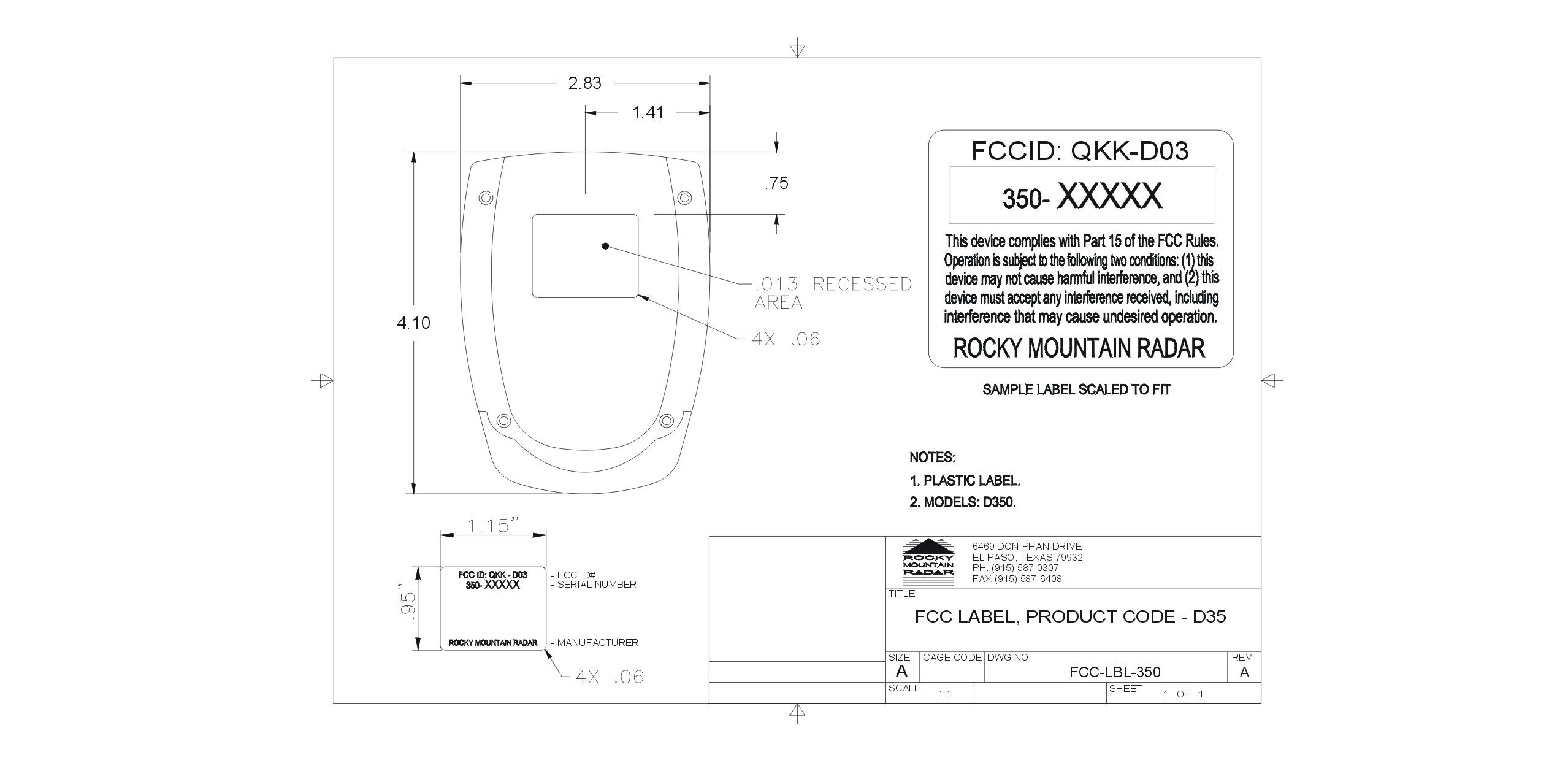
Document Text
Text extracted from the exhibit documents filed with the FCC. Open a document above to read the original.
Users Manual
1.Introduction Dear Rocky Mountain Radar Owner, Congratulations on your purchase of one of the world’s most sophisticated radar/laser detectors. The RMR-D250 is a completely integrated radar/laser detector which responds not only to all the radar guns in use today, including “Stalker”, but also to the other latest development in speed monitoring devices- the laser gun. This model provides distinct visual and voice alerts to warn you of the presence of X, K, and all kinds of Ka Band radar guns in the front and rear of you. This model also provides the benefit of ‘undetectability’ by alerting you to the presence of VG-2(‘The Radar Detector detector’) It also incorporates a new safety feature – Safety Alert(SA) and Safety Warning System(SWS). This safety feature warns you of the presence of potential road hazards by detecting signals from safety radar transmitting devices. Note: Important : The RMR-D250 is not designed to help you disobey the law. A defensive driver always obeys the posted speed limit and legal driving methods. Federal and Local Regulation The FCC passed the Communications Act in 1934 to give all citizens the right to receive all types of radio transmissions. The same radio frequencies used by police radar are also used by other devices, such as automatic door openers, burgler alarms, and some amateur radio equipment. Since the RMR-D250 is just a radio receiver tuned to a specific portion of the public radio spectrum, it is protected under this act. Some local, state, and federal regulations may prohibit the use of this detection device. Please check with authorities regarding the use of this device before operating it. 2. Control and Features 1) Controls and Functions a. Power On/Off and Volume Control b. Dim Button c. Mute Button d. City Button e. DC 12V Power Input Jack f. Radar Antenna g. Front Laser Detection Lens h. Rear Laser Detection Lens : Receives incoming laser signals from rear i. Speaker j. Power-On Indicator k. X-Band Indicator l. K/Ka Band Indicator m. City Indicator n. Signal Strenth Meter Indicator o. VG-2 Indicator C I T Y D I M K/Ka X P k j l V 4 32 C n m o MUTE b c d g VOL a e DC12V - + i h f RMR-D250 SUPER WIDE BAND O V C I E 3. Installation 1) Mounting Guidelines For the best performance, select the proper location for the unit where it has a direct view of the road. The radar antenna is located behind the rear panel of the unit and the laser detection lenses are located behind the rear panel of the unit and the front window. The antenna and sensors should not be obstructed by metal or metallic surfaces and should be pointed at the horizen for accurate long range detection - Choose a location that does not block the driver’s vision. - Mount the detector in a level position. - Do not mount the detector behind metal surfaces, windshield antenna, wiper blades, ornaments, or mirrored glass. - Heated windshields, currently available as an option on some Ford(Instaclear) or GM(electriclear) vehicles act as an impenetrable barrier to radar signals. - Do not mount the detector where the driver or passenger might collied in the case of an abrupt halt. Note : Whichever mounting method you choose, remember to place the radar detector out of view when you leave your vehicle. This keeps the detector out of sight from thieves and prevents exposure to extremely high temperatures. Note : If necessary, you may adjust the bracket to the proper angle by bending it. To remove your detector pull up the detector from the front pulling it towards you. Caution : On some newer model cars, a plastic safety coating has been applied to the windshield. The suction cups may leave permanent marks on the windshield once they are removed. Check your vehicle owner’s manual to see if your car has the plastic safety coating. 2) Mounting Types A.On Windshield a. Attatch bracket to windshield. b. Bend bracket for correct detection angle. c. Plug Power cord into detector. d. Attatch bracket to detector. e. Plug power cord into cigarette lighter. B. On Dashboard a. Peel protective paper off one side of hook-loop. b.Tape on detector’s bottom. c. Peel top paper off. d. Place detector on dashboard. e. Plug power cord into detector and cigarette lighter. 3) Power Connection The coiled power cord provided with the unit has a cigarette lighter socket plug at one end a small connector on the other. 1. Insert the small connector into the jack on the side of the unit. 2. Insert the other end into the cigarette lighter socket of your vehicle. If the detector does not operate when you turn it on, remove the adapter from the cigarette lighter socket and carefully check the socket for debris. Also, check the fuse in the adapter and your vehicle fuse box. 4) Replacing Fuse a. To replace the fuse, unscrew the top of the plug. b. Remove and check the fuse to see if it has blown, if it has, replace it. 4. Operation 1) Power and Volume Control Turn on and adjust volume. Note : Turning on the detector will trigger the Self-Test mode. 2) Dim Mode Press Dim Button. → A voice sound will alert you that Dim mode has been activated. Each time you press Dim button, display intensity will change Dim, Dimmer, Dark, Bright. (Note : The RMR-D250 cannot activate Mute and Dark at same time. If the MUTE is engaged, the DARK cannot activate.) → Hold down Dim Button for three(3) seconds to select “Voice On” or “Voice Off”. 3) City / Highway Mode Press City Button. →”City” LED turns on for “City” Mode. 4) Mute Mode Press Mute Button. →Silences the tone sound. Note : Press button again to restore tone sound. 5) Select Tone Hold down the Mute button for three seconds. The RMR-D250 will change tone sound. 6) Indicator and Visual a. Power On “P” LED turns on. K/Ka P X 2 C 3 4 V b. X Band Detection “X” LED turns on with voice sound. K/Ka P X 2 C 4 3 V c. K/Ka Band Detection “K/Ka” LED turns on with voice sound. K/Ka P X 2 C 3 4 V d. Laser Alarm “P,X,K/Ka, 2,3,4,V” LEDs flash with voice sound. If the unit detects the laser …
Text truncated - open the document above for the full version.
Users Manual
1.Introduction Dear Rocky Mountain Radar Owner, Congratulations on your purchase of one of the world’s most sophisticated radar/laser detectors. The RMR-DLS350 is a completely integrated radar/laser detector which responds not only to all the radar guns in use today, including “Stalker”, but also to the other latest development in speed monitoring devices- the laser gun. This model provides distinct visual and voice alerts to warn you of the presence of X, K, and all kinds of Ka Band radar guns in the front and rear of you. This model also provides the benefit of ‘undetectability’ by alerting you to the presence of VG-2(‘The Radar Detector-detector’) It also incorporates a new safety feature – Safety Alert(SA) and Safety Warning System(SWS). This safety feature warns you of the presence of potential road hazards by detecting signals from safety radar transmitting devices. Note: Important: The RMR-DLS350 is not designed to help you disobey the law. A defensive driver always obeys the posted speed limit and legal driving methods. Federal and Local Regulations The FCC passed the Communications Act in 1934 to give all citizens the right to receive all types of radio transmissions. The same radio frequencies used by police radar are also used by other devices, such as automatic door openers, burgler alarms, and some amateur radio equipment. Since the RMR-DLS350 is just a radio receiver tuned to a specific portion of the public radio spectrum, it is protected under this act. Some local, state, and federal regulations may prohibit the use of this detection device. Please check with authorities regarding the use of this device before operating it. 2. Control and Features 1) Controls and Functions a. Power On/Off and Volume Control b. Dim Button c. Mute Button d. City Button e. DC 12V Power Input Jack f. Radar Antenna g. Front Laser Detection Lens h. Rear Laser Detection Lens : Receives incoming laser signals from rear i. Speaker j. Power-On Indicator k. X-Band Indicator l. K/Ka Band Indicator m. City Indicator n. Signal Strenth Meter Indicator o. Laser Indicator RMR-DLS350 SUPER WIDE BAND L A S E R D I M MUTE C I TY DC12V + - VOL P X K/Ka C 2 3 4 L h i f g b c d e a j k lm no 3. Installation 1) Mounting Guidelines For the best performance, select the proper location for the unit where it has a direct view of the road. The radar antenna is located behind the rear panel of the unit and the laser detection lenses are located behind the rear panel of the unit and the front window. The antenna and sensors should not be obstructed by metal or metallic surfaces and should be pointed at the horizen for accurate long range detection. - Choose a location that does not block the driver’s vision. - Mount the detector in a level position. - Do not mount the detector behind metal surfaces, windshield antenna, wiper blades, ornaments, or mirrored glass. - Heated windshields, currently available as an option on some Ford(Instaclear) or GM(electriclear) vehicles act as an impenetrable barrier to radar signals. - Do not mount the detector where the driver or passenger might collied in the case of an abrupt halt. Note : Whichever mounting method you choose, remember to place the radar detector out of view when you leave your vehicle. This keeps the detector out of sight from thieves and prevents exposure to extremely high temperatures. Note : If necessary, you may adjust the bracket to the proper angle by bending it. To remove your detector, pull up the detector from the front pulling it towards you. Caution : On some newer model cars, a plastic safety coating has been applied to the windshield. The suction cups may leave permanent marks on the windshield once they are removed. Check your vehicle owner’s manual to see if your car has the plastic safety coating. 2) Mounting Types A.On Windshield a. Attatch bracket to windshield. b. Bend bracket for correct detection angle. c. Plug Power cord into detector. d. Attatch bracket to detector. e. Plug power cord into cigarette lighter. B. On Dashboard a. Peel protective paper off one side of hook-loop. b.Tape on detector’s bottom. c. Peel top paper off. d. Place detector on dashboard. e. Plug power cord into detector and cigarette lighter. 3) Power Connection The coiled power cord provided with the unit has a cigarette lighter socket plug at one end a small connector on the other. 1. Insert the small connector into the jack on the side of the unit. 2. Insert the other end into the cigarette lighter socket of your vehicle. If the detector does not operate when you turn it on, remove the adapter from the cigarette lighter socket and carefully check the socket for debris. Also, check the fuse in the adapter and your vehicle fuse box. 4) Replacing Fuse a. To replace the fuse, unscrew the top of the plug. b. Remove and check the fuse to see if it has blown, if it has, replace it. 4. Operation 1) Power and Volume Control Turn on and adjust volume. Note : Turning on the detector will trigger the Self-Test mode. 2) Dim Mode Press Dim Button. → A voice sound will alert you that Dim mode has been activated. Each time you press Dim button, display intensity will change Dim, Dimmer, Dark, Bright. (Note : The RMR-DLS350 cannot activate Mute and Dark at same time. If the MUTE is engaged, the DARK cannot activate.) → Hold down Dim Button for three(3) seconds to select “Voice On” or “Voice Off”. 3) City / Highway Mode Press City Button. →”City” LED turns on for “City” Mode. 4) Mute Mode Press Mute Button. →Silences the tone sound. Note : Press button again to restore tone sound. 5) Select Tone Hold down the Mute button for three seconds. The RMR-DLS350 will change tone sound. 6) Indicator and Visual a. Power On “P” LED turns on. K/Ka X P L 4 3 2 C b. X Band Detection “X” LED turns on with voice sound. K/Ka P X 2 C 3 4 L c. K/Ka Band Detection “K/Ka” LED turns on with voice sound. K/Ka P X2 C 4 3 L d. Laser Alarm “P,X,K/Ka,2,3,4,L” LEDs flash with voice sound. If the unit detect…
Text truncated - open the document above for the full version.
Cover Letter(s)
December 4, 2002 Federal Communications Commission 7435 Oakland Mills Road Columbia, MD 21046 Gentlemen: This letter is to comply with Section 0.457(d)(2)(i) pertaining to confidential material. Rocky Mountain Radar would like the following documents regarding this submission for FCC ID: QKK-D03 to be kept confidential. 1. Schematic for RMR-DLS350 (all pages) 2. Schematic for RMR-D250 (all pages) 3. Block diagram for RMR-DLS350 4. Block diagram for RMR-D250 The above material contains trade secrets or technical data, which would customarily be guarded from competitors. We do not want these documents to be accessible to the general public. Sincerely, Michael B. Churchman, President
Internal Photos
Internal Assembly Internal Internal Bottom
Internal Photos
Internal Assembly Internal PWBs Internal Bottom
Operational Description
Operating Description The RMR-D250 radar detector is a dual conversion scanning super-heterodyne receiver with separate alarms for each of the radar bands, dim function, city/highway and mute select. It detects front and rear laser and radar. It contains VOICE alerts as well as selectable tones and a digital display of all functions. The RMR-D250 has selectable VG-2, allowing the driver to select whether he wishes to scan for the presence of detector-detectors or not. The RMR-D250 is completely VG- 2/VG-3 undetectable. The RMR-D250 is built with high reliability surface mount construction and VCO technology for improved performance over a wide operating temperature. The RMR- D250 detects all radar and laser bands used by law enforcement: 10,475 – to – 10,575 MHz, 24,050 – to – 24,250 MHz, and 33,400 – to – 36,000 MHz, as well as 904 nanometer infrared signals. The RMR-D250 is compact, designed exclusively for automotive use and is powered by the 12-Volt electrical system in a car or truck.
Operational Description
Operating Description The RMR-DLS350 radar detector is a dual conversion scanning super-heterodyne receiver with separate alarms for each of the radar bands, dim function, city/highway and mute select. It detects front and rear laser and radar. It contains VOICE alerts as well as selectable tones and a digital display of all functions. The RMR-DLS350 has selectable VG-2, allowing the driver to select whether he wishes to scan for the presence of detector-detectors or not. The RMR-DLS350 is completely VG-2/VG-3 undetectable. The RMR-DLS350 is built with high reliability surface mount construction and VCO technology for improved performance over a wide operating temperature. The RMR- DLS350 detects all radar and laser bands used by law enforcement: 10,475 – to – 10,575 MHz, 24,050 – to – 24,250 MHz, and 33,400 – to – 36,000 MHz, as well as 904 nanometer infrared signals. The RMR-DLS350 is compact, designed exclusively for automotive use and is powered by the 12-Volt electrical system in a car or truck.
Test Report
December 16, 2002 Mr. Mike Churchman Rocky Mountain Radar 6469 Doniphan Drive El Paso, TX 79932 Dear Mr. Churchman: Enclosed is the test report for the Rocky Mountain Radar Radar Detector D250/DLS350 tested at our facility, 556 Route 222 in Groton, New York. This facility is on file with the FCC per CFR 47 2.948 (Site File Number 31040/SIT) and is NVLAP accredited. As narrated in the report, the product configuration meets the requirements of the FCC per CFR 47 Part 15 Class B for Unintentional Radiators. Thank you for selecting Diversified T.E.S.T. Technologies, Inc. for your testing needs. We look forward to working with you on future projects. Should you have any questions, or concerns regarding this report please contact me at (800) 724-6452 or (607) 898-4218. Sincerely, Shaun Hotaling Technical Associate DIVERSIFIED T.E.S.T. TECHNOLOGIES, INC. FCC Part 15 Class B TEST REPORT Rocky Mountain Radar Radar Detector, D250/DLS350 Project Number: 5512 This report shall not be reproduced, except in full, without the written approval of DTT, Inc. And must not be used to claim product endorsement by NVLAP or any agency of the U.S. Government. 0 T T E E S S T T R R E E P P O O R R T T FCC per CFR 47 Part 15 Class B December 9, 2002 Prepared for: Rocky Mountain Radar by: Diversified TEST Technologies, Inc. DIVERSIFIED T.E.S.T. TECHNOLOGIES, INC. FCC Part 15 Class B TEST REPORT Rocky Mountain Radar Radar Detector, D250/DLS350 Project Number: 5512 This report shall not be reproduced, except in full, without the written approval of DTT, Inc. And must not be used to claim product endorsement by NVLAP or any agency of the U.S. Government. 1 Table of Contents PRODUCT DESCRIPTION Page 2 TEST SITE INFORMATION Page 3 RADIATED EMISSIONS CALCULATIONS Page 4 RADIATED EMISSIONS TEST PROCEDURE Page 5 DEVIATIONS FROM TEST METHOD Page 5 DIAGRAMS Page 6 PHOTOGRAPHS Page 7 DATA CHARTS Page 8-11 Sections omitted from your report were not required as per the agreed test plan DIVERSIFIED T.E.S.T. TECHNOLOGIES, INC. FCC Part 15 Class B TEST REPORT Rocky Mountain Radar Radar Detector, D250/DLS350 Project Number: 5512 This report shall not be reproduced, except in full, without the written approval of DTT, Inc. And must not be used to claim product endorsement by NVLAP or any agency of the U.S. Government. 2 Standard Information & Product Description STANDARD: FCC Part 15 Class B CLIENT: Rocky Mountain Radar 6469 Doniphan Drive El Paso, TX 79932 PRODUCT: Radar Detector Model #: D250/DLS350 Condition: New PRODUCT RECEIVED: December 6, 2002 TEST DATES: December 9, 2002 PREPARED BY: Diversified TEST Technologies, Inc. 556 Route 222 • PO Box 8 Groton, New York 13073 (607) 898-4218 (607) 898-4830/fax COMPILED BY: Shaun Hotaling Technical Associate REVIEWED BY: Thomas P. Sims President DIVERSIFIED T.E.S.T. TECHNOLOGIES, INC. FCC Part 15 Class B TEST REPORT Rocky Mountain Radar Radar Detector, D250/DLS350 Project Number: 5512 This report shall not be reproduced, except in full, without the written approval of DTT, Inc. And must not be used to claim product endorsement by NVLAP or any agency of the U.S. Government. 3 Test Site Information Location and Registration: • Open field test site, Diversified T.E.S.T. Technologies, Inc., 556 Rte 222 in Groton NY Radiated Emissions: • 30-meter open field • The equipment under test (EUT) was placed at a 1-meter range in an RF transparent shelter. Calibration: • Calibrated to ANSI Procedure C 63.4-1992 • Copy of calibration on file with FCC per Title CFR 47 Section 2.948. Equipment Calibration: • The test equipment used is calibrated by the manufacturer or independent calibration laboratory. • These test results are traceable to NIST, because all calibrations are traceable to NIST standards. Test Performance: • Federal Communication Commissions (FCC) regulations as outlined in Title CFR 47, Part 15, for Class B Unintentional Radiators. • Test procedures used were to CFR 47 15.31, ANSI C 63.4- 1992. • Radiated Emissions per limits 15.109 • Conducted Emissions per limits 15.107 DIVERSIFIED T.E.S.T. TECHNOLOGIES, INC. FCC Part 15 Class B TEST REPORT Rocky Mountain Radar Radar Detector, D250/DLS350 Project Number: 5512 This report shall not be reproduced, except in full, without the written approval of DTT, Inc. And must not be used to claim product endorsement by NVLAP or any agency of the U.S. Government. 4 Radiated Emissions Calculations Diversified T.E.S.T. Technologies, Inc. uses automated data reductions to determine product compliance to radiated emissions regulations. The program is fully automated and plots the signal amplitude against the frequency grid to which it was tested. The plotted charts will print out, in tabular form, the maximized frequencies that were near or over the specification limit. The automatic computation takes into account the programmed parameters required by the FCC specifications; i.e., bandwidth, scan speed and the antenna/cable loss and amplifier gain factors. The product's signal data is compared to a current ambient scan. The frequencies that are of significant amplitude are automatically sorted out by the computer and are brought out to be further analyzed and maximized. These same frequencies are also profiled by rotating the product 360 degrees on the EMCO 12-foot turntable. Test Instruments Used 1. 9 Ridge Horn ANT: Electro-Metrics, Model #: RGA 60, Serial # 2981 2. 9 HP Spectrum Analyzer, Model # 8593EM 3. 9 COAX: PIN Style R/G 142-B/V 4. 9 Power Supply: SORENSEN & Co., Inc., Model #: T50-1.5 5. 9 Printer: EPSON LX-810 DIVERSIFIED T.E.S.T. TECHNOLOGIES, INC. FCC Part 15 Class B TEST REPORT Rocky Mountain Radar Radar Detector, D250/DLS350 Project Number: 5512 This report shall not be reproduced, except in full, without the written approval of DTT, Inc. And must not be used to claim product endorsement by NVLAP or any agency of the U.S. Government. 5 Radiated Emissions Test Procedure The product was tested on our open field range, according to Title C…
Text truncated - open the document above for the full version.
Test Setup Photos
Photographs for Radiated Emissions Photograph #1: Radiated Emissions Photograph #2: Radiated Emissions
Contact Information
Applicant
Michael B Churchman(President)
Technical Contact
CKC Laboratories, IncMary Ellen Clayton
[email protected]209-966-5240
5473A Clouds Rest · Mariposa, California · United States
Non-Technical Contact
CKC Laboratories, IncMary Ellen Clayton
[email protected]209-966-5240
Test Firm
Diversified T.E.S.T. TechnologiesThomas Sims
Technical Specifications
| # | Rule Parts | Frequency Range | Power Output |
|---|---|---|---|
| 3 | 15B | 33.40 GHz - 36.00 GHz | - |
Other Applications from Rocky Mountain Radar

QKK-MC1
Apr 18, 2011RADAR DETECTOR
Equipment Class
DSC - Part 15 Security/Remote Control Transmitter
QKK-TRK
Apr 18, 2011RADAR DETECTOR
Equipment Class
CRD - Part 15 Radar Detector
QKK-RD1
Nov 29, 2005Radar Detector
Equipment Class
CRD - Part 15 Radar Detector
QKK-D10
Nov 29, 2005Radar Detector
Equipment Class
CRD - Part 15 Radar Detector
QKK-D04
Mar 29, 2004Radar Laser Detector
Equipment Class
CRD - Part 15 Radar Detector