QKWPILOT1Control and steering unit for solar inverters
FRONIUS International gmbh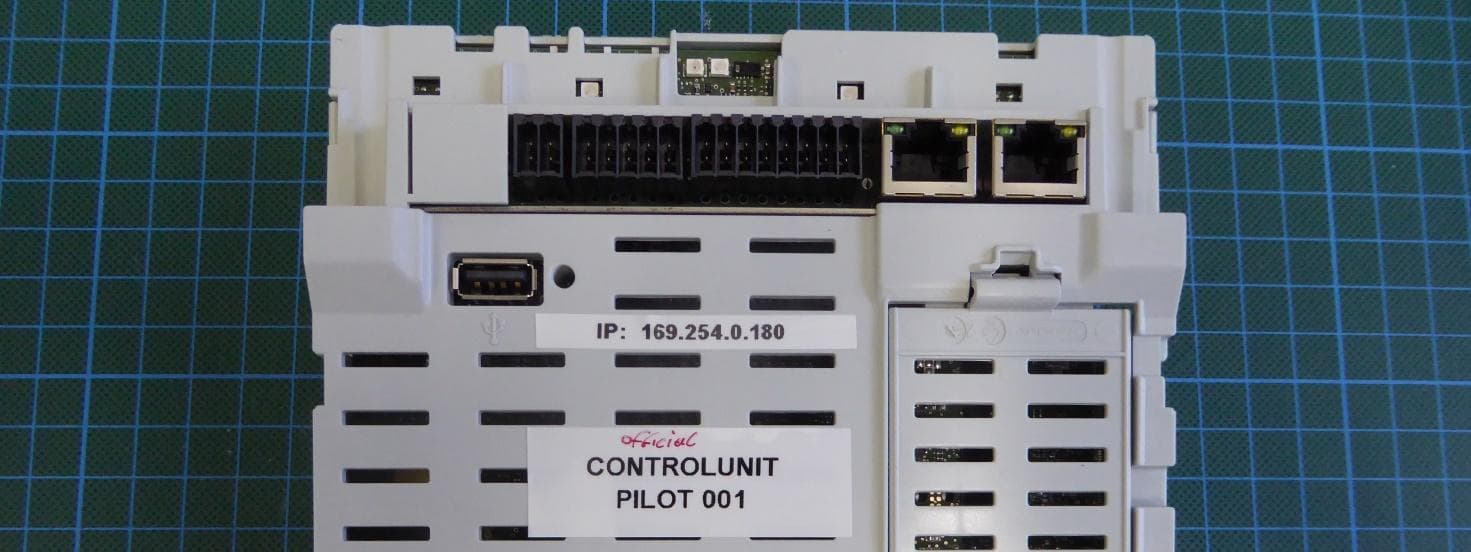
Click to zoom
Application Details
- Equipment Class
- JAB - Part 15 Class B Digital Device
- Date of Grant
- Sep 29, 2024
- Application Purpose
- Original Equipment
- Date of Application
- Sep 29, 2024
- Equipment Note
- Control and steering unit for solar inverters
- Company
- FRONIUS International gmbh
- Country
- Austria
Documents & Files
Document Text
Text extracted from the exhibit documents filed with the FCC. Open a document above to read the original.
Users Manual
Operating In structions Fronius Primo GEN24 3.0 / 3.0 Pl us / 3.6 / 3.6 Plus 4.0 / 4.0 Plus / 4.6 / 4.6 Plus 5.0 / 5.0 Plus / 6.0 / 6.0 Plus 42,0426,0302,EN024-02062024 EN Operating Instructions Contents Safety rules9 Explanation of safety notices9 Safety9 General9 Environmental conditions10 Qualified personnel10 Noise emission values10 EMC measures11 Backup power11 Data protection12 Copyright12 Protective earthing (PE)12 General information13 Fronius Primo GEN2415 Device concept15 Function overview15 Fronius UP16 Scope of supply16 Intended use16 Thermal concept17 Fronius Solar.web17 Local communication18 The various operating modes19 Operating modes – Explanation of symbols19 Operating mode – Inverter with battery20 Operating mode – Inverter with battery and several Smart Meters20 Operating mode - inverter with battery, AC-coupled to another inverter20 Operating mode – Inverter with battery and backup power function21 Operating mode – Inverter with battery, Ohmpilot and backup power function21 Operating mode – Inverter with battery, further inverter and backup power function21 Energy flow dir ection of the inverter 22 Operating states (only for systems with a battery)22 Energy saving mode24 General24 Switch-off conditions24 Switch-on conditions24 Special case24 Indication of energy saving mode25 Suitable batteries26 General26 Limitations in operation 26 BYD Battery-Box Premium26 LG FLEX27 Manual system start29 Requirements29 Notification of system shutdown29 Manual battery start after system shutdown29 Starting backup power operation after a system shutdown29 Protection of people and equipment30 Central grid and system protection30 WSD (wired shutdown)30 RCMU 30 Insulation monitoring30 AFCI - Arc Fault Circuit Interrupter (Arc Guard)30 Safe state31 Surge protective device31 Control elements and connections32 3 Connection area32 Connection area divider33 Ground electrode terminal33 DC disconnector34 Data communication area34 Button functions and LED status indicator35 Internal schematic connection diagram of the IOs37 Backup power variant - PV Point (OP)39 General41 Explanatory note - PV Point/PV Point Comfort41 PV Point (OP)41 PV Point Comfort42 Backup power variant - Full Backup43 General45 Prerequisites for backup power mode45 Transitioning from feeding energy into the grid to backup power mode45 Transitioning from backup power mode to feeding energy into the grid45 Backup power and energy saving mode46 Automatic switch to backup power including backup power circuits and 1-pin separation, e.g. Austria or Austr alia 47 Functions47 Transitioning from feeding energy into the grid to backup power mode47 Transitioning from backup power mode to feeding energy into the grid47 Automatic switch to backup power all-pin separation, e.g. Germany, France, UK, Spain48 Functions48 Transitioning from feeding energy into the grid to backup power mode48 Transitioning from backup power mode to feeding energy into the grid49 Automatic switch to backup power all-pin separation, Italy50 Functions50 Transitioning from feeding energy into the grid to backup power mode50 Transitioning from backup power mode to feeding energy into the grid51 Manual switch to backup power 1-pin separation, e.g. Australia / 2-pin separation, e.g. Ger- man y 52 Functions52 Transitioning from feeding energy into the grid to backup power mode52 Transitioning from backup power mode to feeding energy into the grid53 Installation55 General57 Quick-lock system57 Warning notices on the device57 System component compatibility59 Installation location and position 60 Choosing the location of the inverter60 Choosing the location of third-party batteries61 Installation position of inverter62 Install the mounting bracket and hang up the inverter64 Selecting the fixing material64 Properties of the mounting bracket64 Do not deform the mounting bracket64 Fitting the mounting bracket to a wall64 Installing the mounting bracket on a mast or beam65 Attaching the mounting bracket to mounting rails 66 Attaching the inverter to the mounting bracket66 Prerequisites for connecting the inverter67 Different cable types67 Permissible cables for the electrical connection67 Permissible cables for the data communication connection68 Cable diameter of the AC cable69 4 Cable diameter of the DC cable69 Maximum alternating current fuse protection69 Connecting the inverter to the public grid (AC side)71 Safety71 Connecting the inverter to the public grid (AC side)71 Connecting solar module strings to the inverter74 General comments regarding PV modules74 Safety74 Module array - general information75 Module array configuration 3 ‑ 6 kW75 Connecting the solar module strings to the inverter76 Connecting the battery to the inverter80 Safety80 Connecting the battery on the DC side80 Connecting the LG FLEX ground conductor84 Connecting backup power - PV Point (OP)85 Safety85 Installation85 Testing backup power mode89 Connecting backup power - Full Backup90 Safety90 Automatic switch to backup power 1-pin separation, e.g. Austria or Australia90 Automatic switch to backup power 2-pin separation, e.g. Germany, France, UK, Spain91 Automatic switch to backup power 2-pin double separation with ext. grid and system pro- t ection - e.g. Italy 92 Manual switch to backup power 1-pin separation, e.g. Australia / 2-pin separation, e.g. Ger- man y 92 Testing backup power mode94 Connecting the data communication cable95 Modbus participants95 Routing data communication cables96 Connecting the battery communication cable98 Terminating resistors98 Installing the WSD (wired shutdown)100 Closing and commissioning the inverter101 Closing the inverter's connection area/housing cover, and commissioning101 Starting the inverter for the first time101 Installation with the app102 Installation using the web browser102 Switching off current supply and restarting the inverter104 De-energising the inverter and switching it on again104 Settings - user interface of the inverter105 User settings107 Use…
Text truncated - open the document above for the full version.
Users Manual
Install the mounting bracket and hang up the in- v erter Selecting the fix- ing material Use the corresponding fixing materials depending on the subsurface and observe the screw dimension recommendations for the mounting bracket. The installer is responsible for selecting the correct type of fixing. Properties of the moun ting brack- et The mounting bracket (illustration) can also be used as a guide . The pre-drilled holes on the mounting bracket are intended for screws with a thread diameter of 6-8 mm (0.24-0.32 inches). The distance from the left to the right pre-drilled hole is 406 mm (16 inches). Unevenness on the mounting surface (such as coarse-textured plaster) is largely compensated by the mounting bracket. Do not deform the moun ting bracket NOTE! When fitting the mounting bracket to the wall or column, ensure that the moun ting bracket does not become deformed. A deformed mounting bracket may make it difficult to clip/swivel the inverter in- to position. Fitting the moun ting brack- et to a wall IMPORTANT! When installing the mounting bracket, make sure that it is installed with the ar- row pointing upwards. 64 12 3 Installing the moun ting brack- et on a mast or beam When installing the inverter on a mast or beam, Fr onius recommends using the "Pole clamp" (order no. SZ 2584.000) mounting kit from Rittal GmbH. The "Pole clamp" kit covers the follow- ing dimensions: - Rectangular mast or beam with a side length of 50-150 mm (1.97-5.91 inches) - Round mast or beam with a dia- meter of 40-190 mm (1.57-7.48 inches) 65 Attaching the moun ting brack- et to mounting rails IMPORTANT! The moun ting bracket must be affixed at a minimum of four points. Attaching the in- v erter to the mounting brack- et There are integrated grips on the side of the in verter which facilitate lifting/ attaching. 1 Clip the inverter into the mounting br acket from above. The connections must point downwards. Push the lower part of the inverter into the snap-in tabs until the inverter aud- ibly clicks into place on both sides. Check that the inverter is correctly po- sitioned on both sides. 66 Prerequisites for connecting the inverter Different cable t ypes Solid Multi-stran- ded Fine-stran- ded Fine-stran- ded with f er- rule and col- lar Fine-stran- ded with fer- rule without collar Permissible cabl es for the electrical con- nection Round copper conductors can be connected to the terminals of the inverter as described below. Grid connections with push-in terminal* Sel ect a sufficiently large cable cross section based on the actual device output. Number of pins 3 2.5 – 10 mm 2 AW G 14–8 2.5 – 10 mm 2 AWG 14–8 2.5 – 10 mm 2 AWG 14–8 2.5 – 6 mm 2 AWG 14–10 2.5 – 6 mm 2 AWG 14–10 Grid connections, backup power with push-in terminal* Sel ect a sufficiently large cable cross section based on the actual device output! Number of pins 3 1.5 – 10 mm 2 AW G 16–8 1.5 – 10 mm 2 AWG 16–8 1.5 – 10 mm 2 AWG 16–8 1.5 – 6 mm 2 AWG 16–10 1.5 – 6 mm 2 AWG 16–10 PV/BAT connections with push-in terminal** Sel ect a sufficiently large cable cross section based on the actual device output. Number of pins 2 x 5 4 – 10 mm 2 AW G 12–8 4 – 10 mm 2 AWG 12–8 4 – 10 mm 2 AWG 12–8 4 – 6 mm 2 AWG 12–10 4 – 6 mm 2 AWG 12–10 Ground electrode terminal (6-pin) Sel ect a sufficiently large cable cross section based on the actual device output. Number of pins 67 Ground electrode terminal (6-pin) Sel ect a sufficiently large cable cross section based on the actual device output. 2 2.5 – 16 mm 2 AW G 14–6 2.5 – 16 mm 2 AWG 14–6 2.5 – 16 mm 2 AWG 14–6 2.5 – 16 mm 2 AWG 14–6 2.5 – 16 mm 2 AWG 14–6 4 2.5 – 10 mm 2 AW G 14–8 2.5 – 10 mm 2 AWG 14–8 2.5 – 10 mm 2 AWG 14–8 2.5 – 10 mm 2 AWG 14–8 2.5 – 10 mm 2 AWG 14–8 *According to product standard IEC 62109, the ground conductor must corr espond to the phase cross-section for phase cross-sections ≤16 mm², while for phase cross-sections >16 mm², it must be at least 16 mm². For a conductor cross-section of 1.5 mm 2 , the maximum permissible cable length is 100 m. **The cable cross-section must be dimensioned in accordance with the in- stallation situation and the specifications of the battery manufacturer. Permissible cabl es for the data communic- ation connection Cables with the following design can be connected to the terminals of the invert- er: - Copper: round, solid - Copper: round, fine-stranded IMPORTANT! Connect the individual conductors to an appropriate ferrule if several individual conductors are connected to one input of the push-in terminals. WSD connections with push-in terminal Dis- tance max. Strip- ping l ength Cable re- commenda- tion 100 m 109 y d 10 mm 0.39 inch 0.14-1.5 mm 2 AW G 26 - 16 0.14-1.5 mm 2 AWG 26 - 16 0.14-1 mm 2 AWG 26 - 18 0.14-1.5 mm 2 AWG 26 - 16 min. CAT 5 UTP (un- shiel ded twisted pair) Modbus connections with push-in terminal Dis- tance max. Strip- ping l ength Cable re- commenda- tion 300 m 328 y d 10 mm 0.39 inch 0.14-1.5 mm 2 AW G 26 - 16 0.14-1.5 mm 2 AWG 26 - 16 0.14-1 mm 2 AWG 26 - 18 0.14-1.5 mm 2 AWG 26 - 16 min. CAT 5 S TP (shiel- ded twisted pair) IO connections with push-in terminal Dis- tance max. Strip- ping l ength Cable re- commenda- tion 30 m 32 y d 10 mm 0.39 inch 0.14-1.5 mm 2 AW G 26 - 16 0.14-1.5 mm 2 AWG 26 - 16 0.14-1 mm 2 AWG 26 - 18 0.14-1.5 mm 2 AWG 26 - 16 Single con- duc tor pos- sible 68 LAN connections Fronius recommends at least CAT 5 STP (shielded twisted pair) cables and a maximum distance of 100 m (109 y d). Cable diameter of the AC cabl e For a standard M32 cable gland with a reducer: 7-15 mm For a standard M32 cable gland without a reducer: 11-21 mm (with a cable diameter of less than 11 mm, the strain-relief force is reduced from 100 N to a maximum of 80 N) With cable diameters greater than 21 mm, the M32 cable gland must be replaced by an M32 cable gland with a larger clamping area – item number: 42,0407,0780 – strain-relief device M32 x 1.5 KB 18-25. Cable diameter of the DC cabl e Cable diameter for the strain-relief devi…
Text truncated - open the document above for the full version.
Users Manual
00 1 6 7 + - Manufacturer manualManufacturer manual OPTION 1 01 Modbus 1 01 Modbus 0 Modbus 0 / 1 (mi n. CAT 5) Modbus 0 / 1 (mi n. CAT 5) 00 1 6 7 Manufacturer manual OPTION 2 M0 / M1 01 + - Manufacturer manual Modbus 0 / 1 (mi n. CAT 5) Modbus 0 / 1 (mi n. CAT 5) + - Manufacturer manual OPTION 3 M0 / M1 01 00 1 6 7 Manufacturer manual Modbus 0 / 1 (mi n. CAT 5) Modbus 0 / 1 (mi n. CAT 5) 99 Installing the WSD (wir ed shutdown) IMPORTANT! The push-in WSD t erminal in the in- verter's connection area is delivered with a bypass ex works as standard. The bypass must be removed when in- stalling a trigger device or a WSD chain. The WSD switch of the first inverter with connected trigger device in the WSD chain must be in position 1 (primar y device). The WSD switch of all other invert- ers should be in the 0 (secondary device) position. Max. distance between 2 devices: 100 m Max. number of devices: 28 IN (+) IN (-) OUT (+) OUT (-) IN (+) IN (-) OUT (+) OUT (-) IN (+) IN (-) OUT (+) OUT (-) CAT 5/6/7 * * Floating contact of the trigger device (e.g. central grid and system protection). If se veral floating contacts are used in a WSD chain, they must be connected in series. 100 Closing and commissioning the inverter Closing the in- v erter's connec- tion area/hous- ing cover, and commissioning NOTE! The housing cover is fitted with a lock for safety reasons, which allows the hous- ing co ver on the inverter to be pivoted only when the DC disconnector is switched off. ▶ Only clip and pivot the housing cover onto the inverter when the DC discon- nector is switched off. ▶ Do not use excessive force to clip in and pivot the housing cover. 1 Place the cover on the connection ar ea. Tighten the five screws by rotat- ing them 180° to the right in the indic- ated order using a screwdriver (TX20). 2 Clip the housing cover in at the top of the in verter. Press on the lower part of the housing cover and tighten the two screws 180° to the right using a Torx screwdriver (TX20). Turn the DC disconnector to the "On" switch position. Switch on the auto- matic circuit breaker. For systems with a battery, observe the switch-on se- quence as per chapter Suitable batter- ies on page 26. IMPORTANT! Open WLAN Access Point with the optical sensor, see chapter Button functions and LED status indicator on page 35 Starting the in- v erter for the first time When starting the inverter for the first time, various setup settings must be con- figured. If the setup process is cancelled before the process is complete, any data that has been input up to this point is lost and the start screen with the installation wizard is shown again. If the process is interrupted, such as in the event of a power outage, the data is saved. Commissioning may be continued from the point at which the process was interrupted once the power supply has been restored. If the setup was interrupted, the inverter feeds energy into the grid at maximum 500 W and the operating status LED flashes yellow. 101 The country setup can only be set when starting the inverter for the first time. If the coun try setup needs to be changed at a later date, please contact your in- staller / Technical Support team. Installation with the app The "Fronius Solar.start" app is required for this installation method. Depending on the end device with which the installation will be carried out, download the app for the respective platform. 12 open access point Fronius Solar.start 1 Download and install the Fronius Solar.start app. 2 Open the access point by touching the sensor ü Communication LED flashes bl ue. 3 Open the Solar.start app and follow the installation wizard. Scan the QR code on the r ating plate with a smartphone or tablet to connect to the inverter. 4 Add system components in Solar.web and start up the PV system. The network wizard and the product setup can be carried out independently of each o ther. A network connection is required for the Solar.web installation wiz- ard. Installation us- ing the w eb browser WLAN: open access point 192.168.250.181 2 1 Secured Password: FRONIUS_Serialnumber XXXXXXXX Rating plate Access point password: XXXXXXXX 1 Open the access point by touching the sensor ü Communication LED flashes bl ue. 2 Establish the connection to the inverter in the network settings (the inverter is displayed with the name "FRONIUS_" and the serial number of the device). 3 Enter the password from the rating plate and confirm. IMPORTANT! To enter the password on a Windows 10 operating system, the link "Connect using a security key instead" must first be activated to establish a connection with the password. 102 4 In the browser address bar, enter and confirm the IP address 192.168.250.181. The installa tion wizard is opened. 5 Follow the installation wizard in the individual sections and complete the in- stalla tion. 6 Add system components in Solar.web and start up the PV system. The network wizard and the product setup can be carried out independently of each o ther. A network connection is required for the Solar.web installation wiz- ard. Ethernet: 1 open access point 192.168.250.180 2 1 Establish a connection to the inverter (LAN1) with a network cable (CAT5 S TP or higher). 2 Open the access point by touching the sensor once ü Communication LED flashes bl ue. 3 In the browser address bar, enter and confirm IP address 169.254.0.180. The installa tion wizard is opened. 4 Follow the installation wizard in the individual sections and complete the in- stalla tion. 5 Add system components in Solar.web and start up the PV system. The network wizard and the product setup can be carried out independently of each o ther. A network connection is required for the Solar.web installation wiz- ard. 103 Switching off current supply and restarting the in verter De-energising the inverter and switching it on again 1 1. T urn off the automatic circuit breaker. 2. Turn the DC disconnector to the "Off" switch position. To start up the inverter again, follow the steps…
Text truncated - open the document above for the full version.
Users Manual
DC Voltage 1 PUSH 1 PV+ / PV- 2 3 4 Remove the DC push-in terminals from the sl ots and disconnect them from the cables (only necessary if the in- stallation already exists). PV1+ PV2+ P V2- PV1- PV1 + PV1 + PV2 + PV2 + BAT + PV1 - PV 1 - PV2 - PV2 - BAT - PV+ 1 2 PV- 5 Connect the supplied PV+/PV- cables t o the respective connections. IMPORTANT! Note the labelling of the cables when connecting. 6 Connect the supplied cables to the re- spec tive connections on the PC board. IMPORTANT! The plugs must be connected onto the PC board as far as they will go. 148 7 Insert the PC board into the inverter and secur e with the four screws (TX20) supplied at a torque of 1.0 ‑ 1.2 Nm. § Na tional Standards 2 1 0 m m min. 6mm² - max. 16mm² CU-Wire min . 75°C / 167°F 1,5 Nm TX 20 Ø10mm max. Ø4 m m 8 IMPORTANT! Depending on na tional standards and guidelines, a larger cross section of the ground conductor may be required. Dimension the cable cross section of the ground conductor according to the national standards and guidelines and fit a ring cable lug (inner diameter: 4 mm, outer diameter: max. 10 mm) as well as a corresponding ferrule. Fasten the ground conductor to the PC board with a torque of 1.5 Nm. 9 Fasten the ground conductor to the fir st input from the bottom of the ground electrode terminal using a screwdriver (TX20) and a torque of 1.8 - 2 Nm. IMPORTANT! The use of other inputs can make it difficult to insert the connection area divider or damage the ground conduct- or. 149 10 Strip the insulation on the single con- duc tors by 12 mm and secure to the corresponding slot of the terminal on the PC board with a torque of 1.2 - 1.5 Nm. IMPORTANT! The cable cross-section must be selec- ted according to the specifications for the respective inverter power category (see chapter Permissible cables for the electrical connection on page 67). 2 1 "click" 11 Push the DC push-in terminals into the corr esponding slot until there is an audible click. 1 12 Re-insert the connection area divider. * La y the ground conductor in the in- tegrated cable duct. IMPORTANT! Make sure when inserting the connec- tion area divider that the ground con- ductor is not damaged (kinked, pinched, crushed, etc.). 150 1 WSD 13 Remove the factory installed bypass on the push-in WSD t erminal. 1 2 IN- & IN+ 14 Connect the signal cable to the push- in WSD t erminal on the IN- and IN+ slots, observing the labelling. 15 Check whether the WSD switch is in position 1, adjust if necessar y (factory setting: position 1). 151 16 Place the cover on the connection ar ea. Tighten the five screws by rotat- ing them 180° to the right in the indic- ated order using a screwdriver (TX20). 17 Clip the housing cover onto the invert- er fr om above. Press on the lower part of the housing cover and tighten the two screws by rotating them 180° to the right using a screwdriver (TX20). Commissioning the inverter 1 Connect the solar module strings (+/-). Swit ch on the battery connected to the inverter. 152 2 Set the DC disconnector to the "On" s witch position. Switch on the auto- matic circuit breaker. 153 DC Connector Kit GEN24 GeneralThe DC Connector Kit GEN24 (item no.: 4,240,046) enables the connection of PV connec tion strings with a total current above 25 A. General com- men ts regarding PV modules To enable suitable PV modules to be chosen and to use the inverter as efficiently as possible, it is important to bear the following points in mind: - If insolation is constant and the temperature is falling, the open-circuit voltage of the PV modules will increase. The open-circuit voltage must not exceed the maximum permissible system voltage. If the open-circuit voltage exceeds the specified values, the inverter will be destroyed and all warranty claims will be forfeited. - The temperature coefficients on the data sheet of the PV modules must be observed. - Exact values for sizing the PV modules can be obtained using suitable calcu- lation tools, such as the Fronius Solar.creator. IMPORTANT! Before connecting up the PV modules, check that the voltage for the PV mod- ules specified by the manufacturer corresponds to the actual measured voltage. IMPORTANT! The PV modul es connected to the in- verter must comply with the IEC 61730 Class A standard. IMPORTANT! Solar module strings must not be earthed. Safety WARNING! Danger due to incorrect operation and incorrectly performed work. This can r esult in serious injury and damage to property. ▶ Commissioning as well as maintenance and service work in the power module of the inverter must only be carried out by service personnel trained by Fronius and only within the scope of the respective technical regulations. ▶ Read the Installation and Operating Instructions before installing and com- missioning the equipment. 154 WARNING! Danger due to grid voltage and DC voltage from solar modules that are exposed t o light. This can result in serious injury and damage to property. ▶ Ensure that the AC and DC side of the inverter are de-energised before car- rying out any connection, maintenance or service tasks. ▶ Only an authorised electrical engineer is permitted to connect this equip- ment to the public grid. WARNING! Danger due to damaged and/or contaminated terminals. This can result in serious injury and damage to property. ▶ Before making any connections, check the terminals for damage and con- tamination. ▶ Remove contamination in the de-energized state. ▶ Have defective terminals repaired by an authorised specialist. Scope of supplyThe DC Connector Kit GEN24 is an optional extra and can be retrofitted to the in verter. 1. User Inf ormation 2. 2 TX20 screws 3. DC Connector Kit GEN24 De-energising the in verter AC~ OFF 1 ON OFF 2 1 Turn off the automatic circuit breaker. Se t the DC disconnector to the "Off" switch position. 155 2 Disconnect connections from the solar modul e strings (+/-). Switch off the battery connected to the inverter. Wait for the capacitors of the inverter to discharge (2 minutes)…
Text truncated - open the document above for the full version.
Users Manual
4 Disconnect the individual conductors fr om the AC terminal (only necessary if the installation already exists). 5 Remove the mains cable from the in- v erter. 6 Drill out the optional cable guide with a st ep drill. 164 7 Insert the cable gland into the hole and tigh ten to a torque of 6 Nm. 8 Insert the insulating film on the right side of the gr ound electrode terminal. 9 Insert the PC board into the inverter. 165 10 Fasten the PC board with the 4 screws (TX20) supplied and tigh ten to a torque of 1.2 Nm. Strip the insulation of the single conductors by 12 mm. Lift to open the AC ter- minal 's operating lever and insert the stripped single conductor into the slot provided, all the way up to the stop. Then close the operating lever until it en- gages. IMPORTANT! The PEN conductor must be produced with ends that are permanently marked blue, according to the national provisions, and have a cross section of 10 mm². 11 12 Fasten the PEN conductor to the third input of the gr ound electrode terminal from below using a screwdriver (TX20) and a torque of 1.8 – 2 Nm. 166 13 Strip the single conductors according t o the specifications based on the power category of the inverter. The cable cross-section must be selec- ted according to the specifications for the respective power category of the inverter (see chapter Permissible cables for the electrical connection on page 67). IMPORTANT! If necessar y, an automatic circuit breaker with max. 16 A can also be used for protection. In backup power operation, a maximum of 13 A can be provided. The residual current circuit breaker and automatic circuit breaker must be de- signed according to the national provisions 14 Connect the phase/neutral conductors t o the terminals provided. Fasten the ground conductor at the first input to the ground electrode terminal using a screwdriver (TX20) and a torque of 1.8 – 2 Nm. IMPORTANT! The ground conductor must be con- nected with a movement loop so that if the cable gland fails, the ground con- ductor is disconnected last. 15 Connect the stripped phase/neutral conduc tors to the terminals provided. 167 16 Insert the terminals into the respect- iv e slot until they engage. Fasten the union nut of the cable gland to a torque of 4 Nm. 17 Place the cover on the connection ar ea. Tighten the 5 screws by rotating them 180° to the right in the indicated order using a screwdriver (TX20). 18 Clip the housing cover onto the invert- er fr om above. Press on the lower part of the housing cover and tighten the 2 screws by ro- tating them 180° to the right using a screwdriver (TX20). 168 Commissioning the in verter 1 Connect the solar module strings (+/-). Swit ch on the battery connected to the inverter. 2 Set the DC disconnector to the "On" s witch position. Switch on the auto- matic circuit breaker. Configuring PV P oint Comfort Firmware version 1.25.2 or higher is required to commission the PV Point Com- fort. Outdated firmware versions could lead to incompatibilities between the in- verter and PV Point Comfort. In this case, the inverter firmware should be up- dated in accordance with the instructions in Update on page 120. 1 Access the user interface of the inverter. - Open y our web browser. - In the address bar of the browser, enter the IP address (IP address for WLAN: 192.168.250.181, IP address for LAN: 169.254.0.180) or the host and domain name of the inverter and confirm. - The user interface of the inverter is displayed. 2 Click the "De vice configuration" button. 3 Log in to the login area with the "T echnician" user and the technician pass- word. 4 Open the "F unctions and I/Os" menu. 5 Enable "Back up power" mode. 6 Select "PV P oint" in the "Backup power mode" drop-down list. 7 Click the "Sa ve" button to save the settings. "PV Point" backup power mode has been configured. 169 Testing backup po wer mode After the initial installation and configuration of the backup power operation, it is recommended to test the backup power operation. For test mode, a battery charge of min. 30 % is recommended. A description on how to run test mode can be found in the backup power check- list (https://www.fronius.com/en/search-page, item number: 42,0426,0365). 170 Appendix 171 172 Care, maintenance and disposal GeneralThe inverter is designed in such a way that no additional maintenance work builds up . Nevertheless, a few points must be considered during operation to ensure that the inverter works perfectly. CleaningClean the inverter as required with a damp cloth. Do no t use cleaning agents, abrasives solvents or similar to clean the inverter. MaintenanceMaintenance and servicing may only be carried out by Fronius-trained service t echnicians. SafetyThe DC disconnector is used only to switch off power to the power stage set. When the DC disconnec tor is turned off, the connection area is still energized. WARNING! Danger from grid voltage and DC voltage from PV modules. This can r esult in serious injury and damage to property. ▶ The connection area must only be opened by an authorised electrician. ▶ The separate power stage set area must only be opened by Fronius-trained service technicians. ▶ Prior to any connection work, disconnect the inverter on the AC side and the DC side. WARNING! Danger of residual voltage from capacitors. This can result in serious injury and damage to property. ▶ Allow the capacitors of the inverter to discharge (2 minutes). Operation in dust y environ- ments NOTE! If the inverter is operated in dusty environments, dirt may build up on the heat sink and f an. This may result in a loss of power due to insufficient cooling of the inverter. ▶ Make sure that the ambient air can always flow through the inverter's ventila- tion slots unimpeded. ▶ Remove any build-up of dirt on the heat sink and the fan. 173 1 Switch off power to the inverter and w ait for the specified time until the ca- pacitors have discharged and the fan has shut down. Turn the DC disconnector to the "Off" switch position. 2 Loosen …
Text truncated - open the document above for the full version.
Contact Information
Applicant
Peter Boxleitner(Mr.)
Test Firm
PHOENIX TESTLAB GmbHHolger Bentje
Technical Specifications
| # | Rule Parts | Frequency Range | Power Output |
|---|---|---|---|
| 1 | 15B | - | - |
Other Applications from FRONIUS International gmbh
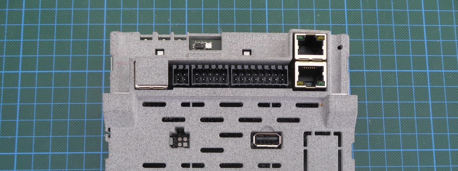
QKWPILOT3
Jun 30, 2026Control and steering unit for solar inverters
Equipment Class
DTS - Digital Transmission System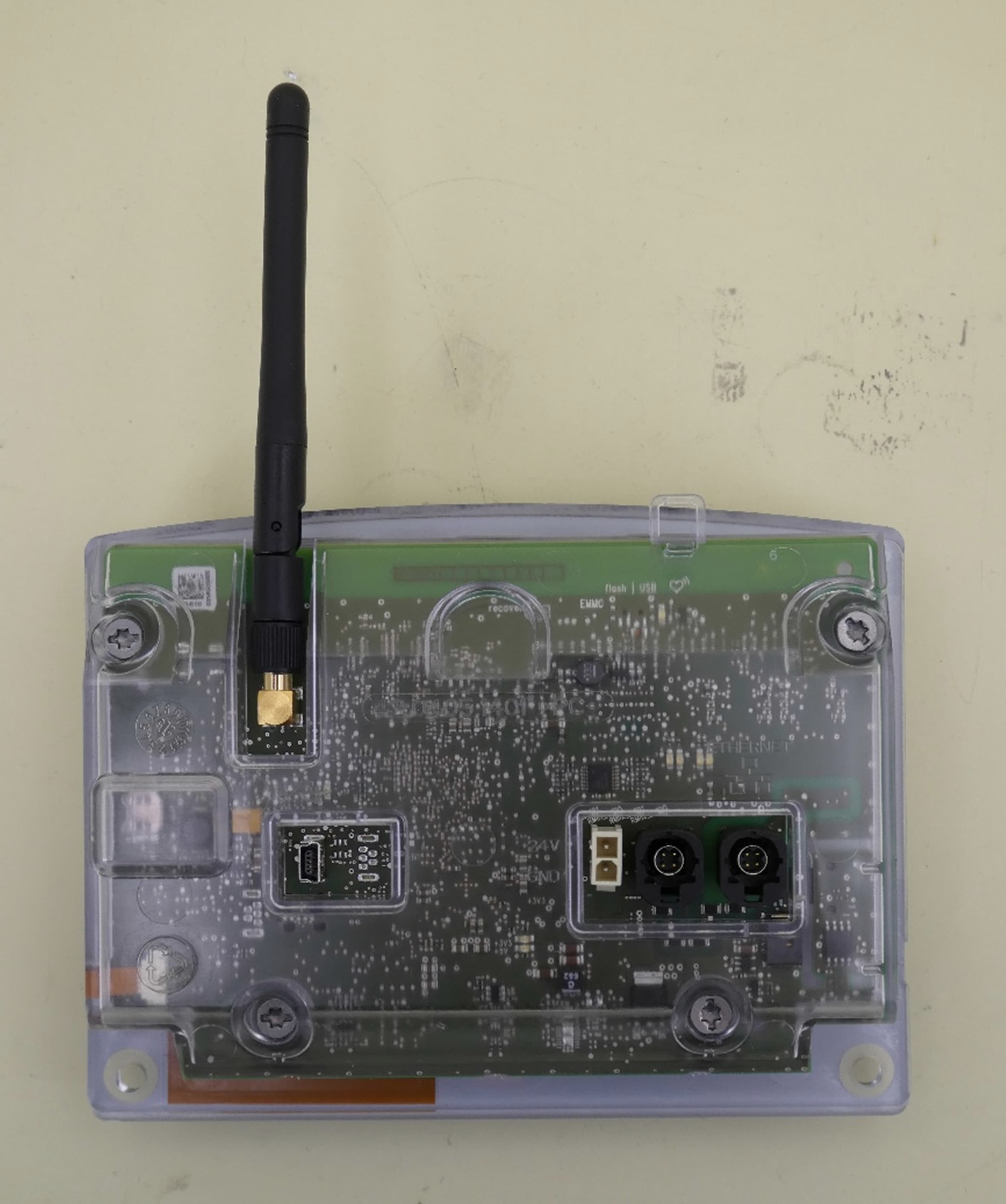
QKWBCU2
Jan 29, 2026Control unit for welding inverters
Equipment Class
JAB - Part 15 Class B Digital Device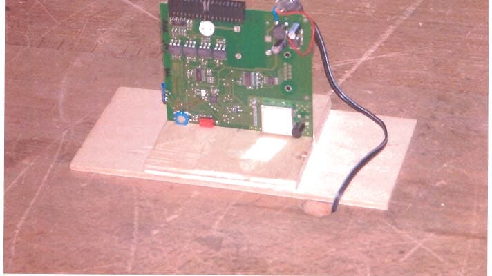
QKWFRF905
Sep 11, 2005Transceiver module
Equipment Class
DSS - Part 15 Spread Spectrum Transmitter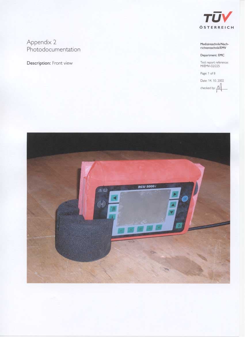
QKWRF5000I
Feb 11, 2003Radio frequency identification system
Equipment Class
DCD - Part 15 Low Power Transmitter Below 1705 kHz