QKWPILOT3Control and steering unit for solar inverters
FRONIUS International gmbh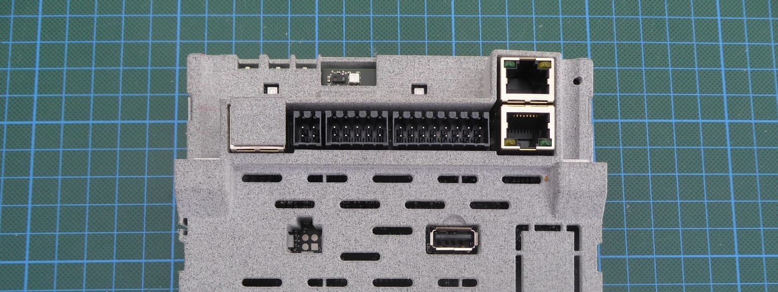
Click to zoom
Application Details
- Equipment Class
- DTS - Digital Transmission System
- Date of Grant
- Jun 30, 2026
- Application Purpose
- Original Equipment
- Equipment Note
- Control and steering unit for solar inverters
- Frequency Range
- 2412.00000000 - 2462.00000000
- Company
- FRONIUS International gmbh
- Country
- Austria
Documents & Files
Document Text
Text extracted from the exhibit documents filed with the FCC. Open a document above to read the original.
Users Manual
Operating In structions Fronius Primo GEN24 3.0 / 3.0 Pl us / 3.6 / 3.6 Plus 4.0 / 4.0 Plus / 4.6 / 4.6 Plus 5.0 / 5.0 Plus / 6.0 / 6.0 Plus 42,0426,0302,EN024-02062024 EN Operating Instructions Contents Safety rules9 Explanation of safety notices9 Safety9 General9 Environmental conditions10 Qualified personnel10 Noise emission values10 EMC measures11 Backup power11 Data protection12 Copyright12 Protective earthing (PE)12 General information13 Fronius Primo GEN2415 Device concept15 Function overview15 Fronius UP16 Scope of supply16 Intended use16 Thermal concept17 Fronius Solar.web17 Local communication18 The various operating modes19 Operating modes – Explanation of symbols19 Operating mode – Inverter with battery20 Operating mode – Inverter with battery and several Smart Meters20 Operating mode - inverter with battery, AC-coupled to another inverter20 Operating mode – Inverter with battery and backup power function21 Operating mode – Inverter with battery, Ohmpilot and backup power function21 Operating mode – Inverter with battery, further inverter and backup power function21 Energy flow dir ection of the inverter 22 Operating states (only for systems with a battery)22 Energy saving mode24 General24 Switch-off conditions24 Switch-on conditions24 Special case24 Indication of energy saving mode25 Suitable batteries26 General26 Limitations in operation 26 BYD Battery-Box Premium26 LG FLEX27 Manual system start29 Requirements29 Notification of system shutdown29 Manual battery start after system shutdown29 Starting backup power operation after a system shutdown29 Protection of people and equipment30 Central grid and system protection30 WSD (wired shutdown)30 RCMU 30 Insulation monitoring30 AFCI - Arc Fault Circuit Interrupter (Arc Guard)30 Safe state31 Surge protective device31 Control elements and connections32 3 Connection area32 Connection area divider33 Ground electrode terminal33 DC disconnector34 Data communication area34 Button functions and LED status indicator35 Internal schematic connection diagram of the IOs37 Backup power variant - PV Point (OP)39 General41 Explanatory note - PV Point/PV Point Comfort41 PV Point (OP)41 PV Point Comfort42 Backup power variant - Full Backup43 General45 Prerequisites for backup power mode45 Transitioning from feeding energy into the grid to backup power mode45 Transitioning from backup power mode to feeding energy into the grid45 Backup power and energy saving mode46 Automatic switch to backup power including backup power circuits and 1-pin separation, e.g. Austria or Austr alia 47 Functions47 Transitioning from feeding energy into the grid to backup power mode47 Transitioning from backup power mode to feeding energy into the grid47 Automatic switch to backup power all-pin separation, e.g. Germany, France, UK, Spain48 Functions48 Transitioning from feeding energy into the grid to backup power mode48 Transitioning from backup power mode to feeding energy into the grid49 Automatic switch to backup power all-pin separation, Italy50 Functions50 Transitioning from feeding energy into the grid to backup power mode50 Transitioning from backup power mode to feeding energy into the grid51 Manual switch to backup power 1-pin separation, e.g. Australia / 2-pin separation, e.g. Ger- man y 52 Functions52 Transitioning from feeding energy into the grid to backup power mode52 Transitioning from backup power mode to feeding energy into the grid53 Installation55 General57 Quick-lock system57 Warning notices on the device57 System component compatibility59 Installation location and position 60 Choosing the location of the inverter60 Choosing the location of third-party batteries61 Installation position of inverter62 Install the mounting bracket and hang up the inverter64 Selecting the fixing material64 Properties of the mounting bracket64 Do not deform the mounting bracket64 Fitting the mounting bracket to a wall64 Installing the mounting bracket on a mast or beam65 Attaching the mounting bracket to mounting rails 66 Attaching the inverter to the mounting bracket66 Prerequisites for connecting the inverter67 Different cable types67 Permissible cables for the electrical connection67 Permissible cables for the data communication connection68 Cable diameter of the AC cable69 4 Cable diameter of the DC cable69 Maximum alternating current fuse protection69 Connecting the inverter to the public grid (AC side)71 Safety71 Connecting the inverter to the public grid (AC side)71 Connecting solar module strings to the inverter74 General comments regarding PV modules74 Safety74 Module array - general information75 Module array configuration 3 ‑ 6 kW75 Connecting the solar module strings to the inverter76 Connecting the battery to the inverter80 Safety80 Connecting the battery on the DC side80 Connecting the LG FLEX ground conductor84 Connecting backup power - PV Point (OP)85 Safety85 Installation85 Testing backup power mode89 Connecting backup power - Full Backup90 Safety90 Automatic switch to backup power 1-pin separation, e.g. Austria or Australia90 Automatic switch to backup power 2-pin separation, e.g. Germany, France, UK, Spain91 Automatic switch to backup power 2-pin double separation with ext. grid and system pro- t ection - e.g. Italy 92 Manual switch to backup power 1-pin separation, e.g. Australia / 2-pin separation, e.g. Ger- man y 92 Testing backup power mode94 Connecting the data communication cable95 Modbus participants95 Routing data communication cables96 Connecting the battery communication cable98 Terminating resistors98 Installing the WSD (wired shutdown)100 Closing and commissioning the inverter101 Closing the inverter's connection area/housing cover, and commissioning101 Starting the inverter for the first time101 Installation with the app102 Installation using the web browser102 Switching off current supply and restarting the inverter104 De-energising the inverter and switching it on again104 Settings - user interface of the inverter105 User settings107 Use…
Text truncated - open the document above for the full version.
Users Manual
Information Class: Confidential Annex to Operating Instructions Fronius Primo GEN24 3.0 / 3.0 Plus / 3.6 / 3.6 Plus 4.0 / 4.0 Plus / 4.6 / 4.6 Plus 5.0 / 5.0 Plus / 6.0 / 6.0 Plus Regulatory Compliance Info FCC ID: QKWPILOT3 This device complies with part 15 of the FCC Rules. Operation is subject to the following two conditions: (1) This device may not cause harmful interference, and (2) this device must accept any interference received, including interference that may cause undesired operation. Changes or modifications not expressly approved by the party responsible for compliance could void the user's authority to operate the equipment. Note: This equipment has been tested and found to comply with the limits for a Class B digital device, pursuant to part 15 of the FCC Rules. These limits are designed to provide reasonable protection against harmful interference in a residential installation. This equipment generates, uses and can radiate radio frequency energy and, if not installed and used in accordance with the instructions, may cause harmful interference to radio communications. However, there is no guarantee that interference will not occur in a particular installation. If this equipment does cause harmful interference to radio or television reception, which can be determined by turning the equipment off and on, the user is encouraged to try to correct the interference by one or more of the following measures: —Reorient or relocate the receiving antenna. —Increase the separation between the equipment and receiver. —Connect the equipment into an outlet on a circuit different from that to which the receiver is connected. —Consult the dealer or an experienced radio/TV technician for help. This equipment complies with FCC radiation exposure limits set forth for an uncontrolled environment. This equipment should be installed and operated with minimum distance 20 cm between the radiator & your body. IC: 12270A-PILOT3 This device contains licence-exempt transmitter(s)/receiver(s) that comply with Innovation, Science and Economic Development Canada’s licence-exempt RSS(s). Operation is subject to the following two conditions: 1.This device may not cause interference. 2.This device must accept any interference, including interference that may cause undesired operation of the device. This equipment complies with IC RSS-102 radiation exposure limits set forth for an uncontrolled environment. This equipment should be installed and operated with minimum distance 20 cm between the radiator & your body. L’émetteur/récepteur exempt de licence contenu dans le présent appareil est conforme aux CNR d’Innovation, Sciences et Développement économique Canada applicables aux appareils radio exempts de licence. L’exploitation est autorisée aux deux conditions suivantes: 1.L’appareil ne doit pas produire de brouillage; 2.L’appareil doit accepter tout brouillage radioélectrique subi, même si le brouillage est susceptible d’en compromettre le fonctionnement. Cet équipement est conforme à l'exposition aux rayonnements IC RSS‐102 des limites définies pour un environnement non contrôlé. Cet équipement doit être installé et utilize avec un minimum de 20 cm de distance entre le radiateur et votre corps.
Attestation Statements
SPE-19-8-069-A GW.40.2153 Dipole Terminal Mount Part No: GW.40.2153 Description: 2.4~2.5GHz/4.9~5.85GHz Terminal Dipole Antenna Features: RP-SMA(M) Straight Connector Hinge Rotatable TPU Housing Total Length: 109mm Diameter: 10mm RoHS & REACH Compliant 2 SPE-19-8-069-A www.taoglas.com Taoglas makes no warranties based on the accuracy or completeness of the contents of this document and reserves the right to make changes to specifications and product descriptions at any time without notice. Taoglas reserves all rights to this document and the information contained herein. Reproduction, use or disclosure to third parties without express permission is strictly prohibited. 1. Introduction 3 2. Specifications 4 3. Antenna Characteristics 5 4. 2D Radiation Patterns 7 5. Mechanical Drawing 11 6. Packaging 12 Changelog 13 3 SPE-19-8-069-A www.taoglas.com The Taoglas GW.40 is a dual-band Wi-Fi ® terminal mount antenna with a RP-SMA(M) connector. The dipole design makes it ideal for 2.4-2.5GHz/4.9-5.85GHz wireless applications such as Bluetooth® and Wireless LAN. At just 109mm in length, it has an omnidirectional radiation pattern. It has a gain value of 3.74dBi at 2.4GHz and 2.5dBi for 5GHz and ensures constant reception and transmission when integrated correctly. Typical applications include: • Routers/Gateways • Industrial IoT • Connected Enterprise The antenna structure is designed with a robust TPU enclosure with a high quality finish. The antenna can be rotated 90 degrees on the base hinge for ease of placement. The GW.40 can be installed in MIMO configurations and orientated away from each other to improve isolation if necessary. Contact your regional Taoglas Customer Support Team if you require installation instructions or any further support. 1. Introduction 4 SPE-19-8-069-A www.taoglas.com Electrical Frequency 2.4 ~ 2.5GHz, 4.9 ~ 5.85GHz Peak Gain Straight -0.32 3.01 Bent 3.15 4.39 Average Gain Straight -2.86 -2.06 Bent -1.40 -1.32 Efficiency Straight 51.72 62.30 Bent 72.41 73.75 Radiation Omnidirectional Polarization Linear Vertical Power Handling 2W Impedance 50Ω Mechanical Antenna Cover TPU Antenna Base Nylon Color Black Connector RP-SMA(M) Weight 10g Environmental Operation Temperature -40°C ~ +85°C Storage Temperature -40°C ~ +85°C 2. Specifications 5 SPE-19-8-069-A www.taoglas.com 3.1 Return Loss 3.2 Efficiency -30 -25 -20 -15 -10 -5 0 200025003000350040004500500055006000(MHz) Bent Straight (dB) 0 10 20 30 40 50 60 70 80 90 100 200025003000350040004500500055006000 (%) (MHz) Bent Straight 3. Antenna Characteristics 6 SPE-19-8-069-A www.taoglas.com 3.3 Average Gain 3.4 Peak Gain -10 -9 -8 -7 -6 -5 -4 -3 -2 -1 0 200025003000350040004500500055006000 (dB) (MHz) Straight Bent -5 -4 -3 -2 -1 0 1 2 3 4 5 200025003000350040004500500055006000 (dBi) (MHz) Straight Bent 7 SPE-19-8-069-A www.taoglas.com 4. 4.1 Test Setup - Straight Free space 4. 2D Radiation Patterns X Y Z 8 SPE-19-8-069-A www.taoglas.com 4.2 Radiation Patterns - Straight XY Plane X X XZ Plane Z Z YZ Plane Z Z -40 -30 -20 -10 0 10 0 30 60 90 120 150 180 210 240 270 300 330 (dBi) 2400MHz 2450MHz 2500MHz -40 -30 -20 -10 0 10 0 30 60 90 120 150 180 210 240 270 300 330 (dBi) 4900MHz 5150MHz 5550MHz 5850MHz -40 -30 -20 -10 0 10 0 30 60 90 120 150 180 210 240 270 300 330 (dBi) 2400MHz 2450MHz 2500MHz -40 -30 -20 -10 0 10 0 30 60 90 120 150 180 210 240 270 300 330 (dBi) 4900MHz 5150MHz 5550MHz 5850MHz -40 -30 -20 -10 0 10 0 30 60 90 120 150 180 210 240 270 300 330 (dBi) 2400MHz 2450MHz 2500MHz -40 -30 -20 -10 0 10 0 30 60 90 120 150 180 210 240 270 300 330 (dBi) 4900MHz 5150MHz 5550MHz 5850MHz X Y Y X Y Y 9 SPE-19-8-069-A www.taoglas.com 4.3 Test Setup - Bent Free space X Y Z 10 SPE-19-8-069-A www.taoglas.com 4.4 Radiation Patterns - Bent XY Plane X X XZ Plane Z Z YZ Plane Z Z -40 -30 -20 -10 0 10 0 30 60 90 120 150 180 210 240 270 300 330 (dBi) 2400MHz 2450MHz 2500MHz -40 -30 -20 -10 0 10 0 30 60 90 120 150 180 210 240 270 300 330 (dBi) 4900MHz 5150MHz 5550MHz 5850MHz -40 -30 -20 -10 0 10 0 30 60 90 120 150 180 210 240 270 300 330 (dBi) 2400MHz 2450MHz 2500MHz -40 -30 -20 -10 0 10 0 30 60 90 120 150 180 210 240 270 300 330 (dBi) 4900MHz 5150MHz 5550MHz 5850MHz -40 -30 -20 -10 0 10 0 30 60 90 120 150 180 210 240 270 300 330 (dBi) 2400MHz 2450MHz 2500MHz -40 -30 -20 -10 0 10 0 30 60 90 120 150 180 210 240 270 300 330 (dBi) 4900MHz 5150MHz 5550MHz 5850MHz X Y Y X Y Y 11 SPE-19-8-069-A www.taoglas.com 5. Mechanical Drawing (Units: mm) 12 SPE-19-8-069-A www.taoglas.com 20pcs GW.40.2153 per Large PE Bag Dimensions - 180*120mm Weight – 200g 1pcs GW.40.2153 per Small PE Bag Dimensions - 100*45mm Weight - 10g 6. Packaging 13 SPE-19-8-069-A www.taoglas.com Changelog for the datasheet SPE-19-8-042 – GW.40.2153 Revision: A (Original First Release) Date: 2019-06-18 Notes: Author: Jack Conroy Previous Revisions 14 SPE-19-8-069-A www.taoglas.com www.taoglas.com © Taoglas
Attestation Statements
Information Class: Confidential To: Federal Communications Commission 7435 Oakland Mills Road Columbia, MD 21046 USA Attestation Certification designating a U.S. Agent for Service of Process Section 2.911(d)(7) (KDB 986446 D01 Covered Equipment) FRONIUS International GmbH (“the applicant”) as required by section 2.911(d)(7), designate below contact located in the United States for purposes of acting as the applicant’s agent for service of process. The applicant also accepts to maintain an agent for no less than one year after the grantee has terminated all marketing and importation or the conclusion of any Commission-related proceeding involving the equipment. The US Agent confirms by the signature, that he has accepted the responsibility to act as the Designated U.S. Agent for Service of Process as required by section 47 CFR 2.911(d)(7) on behalf of the Applicant as noted below. Type of Equipment subject to FCC Certification: Control and steering unit for solar inverters FCC ID: QKWPILOT3 Sincerely yours, Applicant/Grantee US Agent for Service of Process FRN: 0007536717 ☐ FRN: ☒ no FRN – no other business with FCC except US Agent for service of process _________________ _________________ Fronius Int. GmbH Fronius USA LLC Peter Boxleitner Klaus Strassmair Grantee Contact Person Managing Director [email protected] [email protected] Fronius USA LLC 6797 Fronius Drive Portage, IN 46368
Attestation Statements
Information Class: Confidential To: Federal Communications Commission 7435 Oakland Mills Road Columbia, MD 21046 USA Attestation Section 2.911(d)(5)(i) and Section 2.911(d)(5)(ii) (KDB 986446 D01 Covered Equipment) Section 2.911(d)(5)(i) FRONIUS International GmbH (“the applicant”) certifies that the equipment for which authorization is sought is not “covered” equipment prohibited from receiving an equipment authorization pursuant to section 2.903 of the FCC rules. Section 2.911(d)(5)(ii) FRONIUS International GmbH (“the applicant”) certifies that, as of the date of the filing of the application, the applicant is not identified on the Covered List (as a specifically named entity or any of its subsidiaries or affiliates) as an entity producing “covered” equipment. Type of Equipment subject to FCC Certification: Control and steering unit for solar inverters FCC ID: QKWPILOT3 If you have any questions, please feel free to contact me. Contact Person: Peter Boxleitner Position in the Company: Teamleader EMC/EMF Date of Signature: 15.03.2026 ___________________________ Signatory (signature of the applicant)
Cover Letter(s)
Phone: +49(0)5235-9500-0 NMi TESTLAB GmbH [email protected] Königswinkel 10 www.nmi-testlab.de 32825 Blomberg, Germany To: Federal Communications Commission 7435 Oakland Mills Road Columbia, MD 21046 USA Long/Short-term Confidentiality Request FCC ID: QKWPILOT3 To Whom It May Concerns, Pursuant to sections 0.457(d) and 0.459 of CFR 47 and to avoid premature release of sensitive information prior to marketing or release of the product to the public, we hereby request long-term confidential treatment of information accompanying this application as outlined below: ☒ Schematics ☐ Parts List ☒ Block Diagram ☐ Tune-Up Info ☒ Operational Description In addition, we also request the following exhibits contained in this application to be temporarily (short-term confidentiality) withheld from the public disclosure ☐ for an initial period of days ☐ until: ☒ not applicable ☐ External Photos ☐ Test Setup Photos ☐ Internal Photos ☐ Users Manual The above materials contain trade secrets and proprietary information not customarily released to the public. The public disclosure of these matters might be harmful to the applicant and provide unjustified benefits to its competitors. The applicant understands that pursuant to rule 0.457(d), disclosure of this application and all accompanying documentation will not be made before the date of the GRANT for this application. If you have any questions, please feel free to contact me. Contact Person: Sabrina Berghahn Position in the Company: Assistant Test Laboratory RADIO & Authorised Agent
External Photos
Examiner:Bernward ROHDERevision:00 Date of issue: 29.06.2026Order Number: 26-111885page 1 of 7 EUT – 3d top view Examiner:Bernward ROHDERevision:00 Date of issue: 29.06.2026Order Number: 26-111885page 2 of 7 EUT – bottom view Examiner:Bernward ROHDERevision:00 Date of issue: 29.06.2026Order Number: 26-111885page 3 of 7 EUT – top view Examiner:Bernward ROHDERevision:00 Date of issue: 29.06.2026Order Number: 26-111885page 4 of 7 Side view 1 Examiner:Bernward ROHDERevision:00 Date of issue: 29.06.2026Order Number: 26-111885page 5 of 7 Side view 2 Examiner:Bernward ROHDERevision:00 Date of issue: 29.06.2026Order Number: 26-111885page 6 of 7 Side view 3 Examiner:Bernward ROHDERevision:00 Date of issue: 29.06.2026Order Number: 26-111885page 7 of 7 Side view 4
ID Label/Location Info
02/2017 1/2 LABEL LOCATION INFORMATION Model Name: Controlunit PILOT3 Item Number: 43,0001,1844 Front: 02/2017 2/2 Back: Print template
Internal Photos
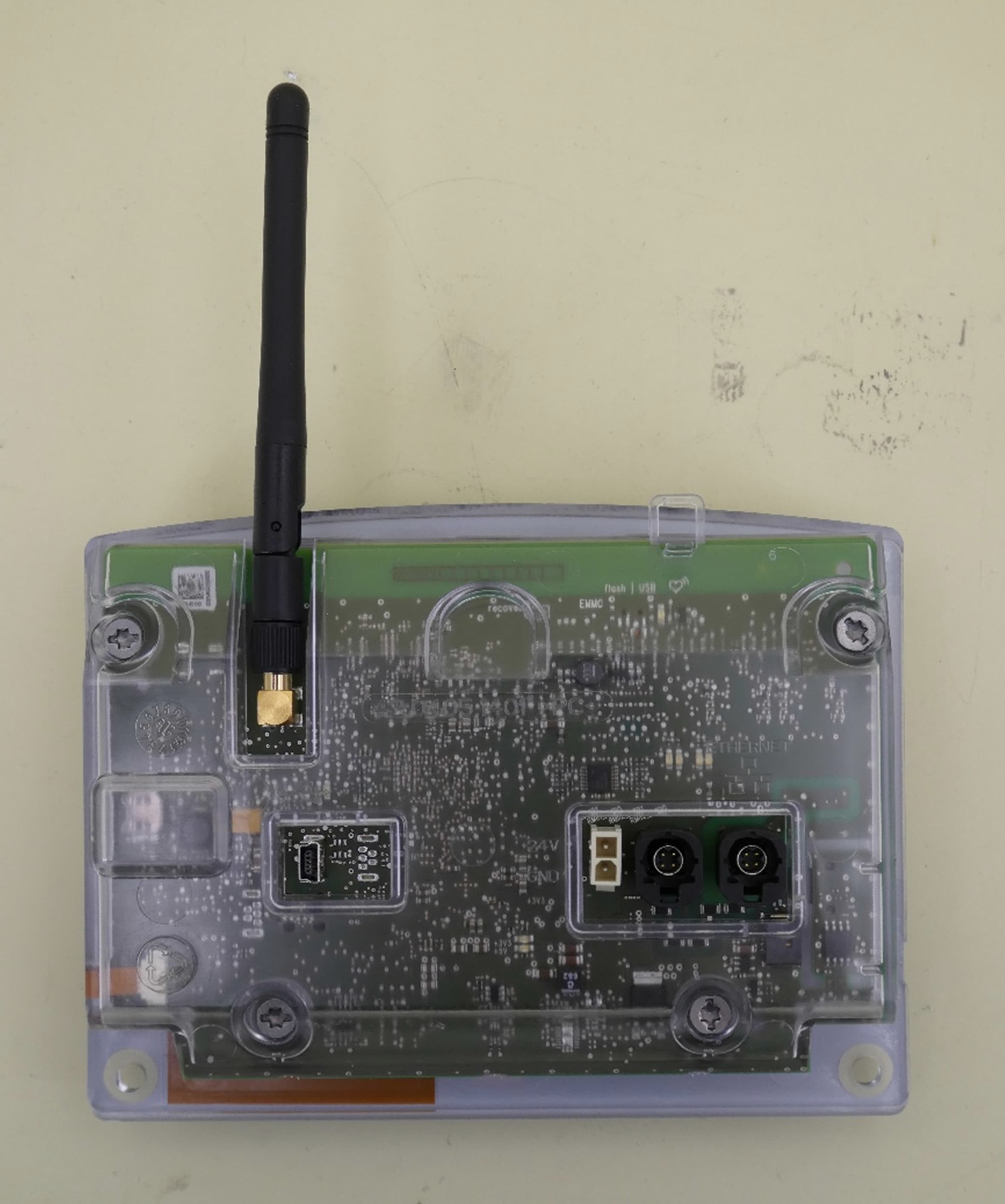
Examiner:Bernward ROHDERevision:00 Date of issue: 29.06.2026Order Number: 26-111885page 1 of 4 EUT – opened – top view Examiner:Bernward ROHDERevision:00 Date of issue: 29.06.2026Order Number: 26-111885page 2 of 4 EUT PCB – top view Examiner:Bernward ROHDERevision:00 Date of issue: 29.06.2026Order Number: 26-111885page 3 of 4 EUT PCB – top view Examiner:Bernward ROHDERevision:00 Date of issue: 29.06.2026Order Number: 26-111885page 4 of 4 Radio part – detail view Radio part and trace design
RF Exposure Info
RF Exposure Evaluation Report Report Number: F251885E8 Equipment under Test (EUT): Controlunit PILOT3 Applicant: Fronius International GmbH Manufacturer: Fronius International GmbH Königswinkel 10 32825 Blomberg, Germany +49 5235 / 9500-0 [email protected] www.nmi-testlab.de Examiner:Mohamed Yassine KHALEKReport Number: F251885E8 Date of Issue: 29.06.2026Order Number: 25-111885Page 2 of 14 References [1]CFR 47 Rule part 1Practice and Procedure [2] CFR 47 Rule part 2Frequency Allocations and Radio Treaty Matters; General Rules and Regulations [3] KDB 447498 D04 Interim General RF Exposure Guidance v01 Examiner:Mohamed Yassine KHALEKReport Number: F251885E8 Date of Issue: 29.06.2026Order Number: 25-111885Page 3 of 14 Test Result The requirements of the tests performed as shown in the overview (clause 4) were fulfilled by the equipment under test. The complete test results are presented in the following. “Passed” indicates that the equipment under test conforms with the relevant limits of the testing standard without taking any measurement uncertainty into account. However, the measurement uncertainty is calculated and shown in this test report. This test report is only valid in its original form. Any reproduction of its contents in extracts without written permission of the accredited test laboratory NMi TESTLAB GmbH is prohibited. The test results herein refer only to the tested sample. NMi TESTLAB GmbH is not responsible for any generalisations or conclusions drawn from these test results concerning further samples. Any modification of the tested samples is prohibited and leads to the invalidity of this test report. Each page necessarily contains the NMi TESTLAB Logo and the TEST REPORT NUMBER. Tested and written by: Signature Reviewed and approved by: Signature Examiner:Mohamed Yassine KHALEKReport Number: F251885E8 Date of Issue: 29.06.2026Order Number: 25-111885Page 4 of 14 Contents:Page Identification ........................................................................................................................... 5 1.1Applicant ............................................................................................................................................ 5 1.2Manufacturer ..................................................................................................................................... 5 1.3Test Laboratory ................................................................................................................................. 5 1.4EUT (Equipment under Test) ............................................................................................................. 6 1.5Technical Data of Equipment ............................................................................................................ 7 Evaluation Methods ................................................................................................................. 9 2.1RF exposure test exemptions for single sources ............................................................................. 9 2.1.1General Exemption CFR 47 §1.1307(b)(3)(i)(A) ........................................................................ 9 2.1.2SAR Based Exemption CFR 47 §1.1307(b)(3)(i)(B) ................................................................... 9 2.1.3MPE Based Exemption CFR 47 §1.1307(b)(3)(i)(C) .................................................................. 9 2.1.4Stand alone MPE evaluation limits .......................................................................................... 10 2.2RF exposure test exemptions for simultaneous transmission sources .......................................... 11 2.2.11 mW Test Exemption for simultaneous transmission sources .............................................. 11 2.2.2Simultaneous transmission SAR based and MPE based test exemptions ............................. 11 2.2.3Test exemption based on the SAR to Peak Location Separation Ratio ................................. 12 Results of evaluation ............................................................................................................. 13 3.1Used evaluation methods................................................................................................................ 13 3.2Evaluation Distance ......................................................................................................................... 13 3.3WLAN 2.4 GHz Emissions ............................................................................................................... 14 Conclusion ............................................................................................................................ 14 Report History ....................................................................................................................... 14 Examiner:Mohamed Yassine KHALEKReport Number: F251885E8 Date of Issue: 29.06.2026Order Number: 25-111885Page 5 of 14 Identification 1.1Applicant Name:Fronius International GmbH Address:Günter-Fronius-Straße 1, 4600 Wels-Thalheim Country:Austria Name for contact purposes:Mr. Jan HERNDLER Phone:+43 7242-241-0 eMail address:[email protected] 1.2Manufacturer Name:Fronius International GmbH Address:Fronius Straße 5, 4642 Sattledt Country:Austria Name for contact purposes:Mr. Jan HERNDLER Phone:+43 7242-241-0 eMail address:[email protected] 1.3Test Laboratory The tests were carried out by:NMi TESTLAB GmbH formerly PHOENIX TESTLAB GmbH Königswinkel 10 32825 Blomberg Germany accredited byDeutsche Akkreditierungsstelle GmbH (DAkkS) according to DIN EN ISO/IEC 17025:2018. The accreditation is only valid for the scope of accreditation listed in the annex of the certificate D-PL-17186-01-00. FCC Test Firm Designation Number DE0004, FCC Test Firm Registration Number 469623, CAB Identifier DE0003 and ISED# 3469A. Examiner:Mohamed Yassine KHALEKReport Number: F251885E8 Date of Issue: 29.06.2026Order Number: 25-111885Page 6 o…
Text truncated - open the document above for the full version.
Test Report
Test Report Report Number: F251885E6 Equipment under Test (EUT): Controlunit PILOT3 Applicant: Fronius International GmbH Manufacturer: Fronius International GmbH Königswinkel 10 32825 Blomberg, Germany +49 5235 / 9500-0 [email protected] www.nmi-testlab.de Examiner:Martin EPPINGERReport Number: F251885E6 Date of Issue: 29.06.2026Order Number: 25-111885Page 2 of 50 References [1] ANSI C63.10-2020 + Cor. 1-2023 + C63.10a-2024 + Errata to C63.10a-2024*, American National Standard of Procedures for Compliance Testing of Unlicensed Wireless Devices *Remark: The errata is not in the accreditation scope of the laboratory yet [2] FCC CFR 47 Part 15, Radio Frequency Devices [3] 558074 D01 15.247 Meas Guidance v05r02 (April 2019), GUIDANCE FOR COMPLIANCE MEASUREMENTS ON DIGITAL TRANSMISSION SYSTEM, FREQUENCY HOPPING SPREAD SPECTRUM SYSTEM, AND HYBRID SYSTEM DEVICES OPERATING UNDER SECTION 15.247 OF THE FCC RULES [4] RSS-247, Issue 4 (2025-07) Digital Transmission Systems, Frequency Hopping Systems and Licence-Exempt Local Area Network Devices in 902-928 MHz, 2400-2483.5 MHz, 5150-5350 MHz, and 5470-5895 MHz bands [5] RSS-Gen, Issue 5 Amendment 2 (2021-02) General Requirements for Compliance of Radio Apparatus Examiner:Martin EPPINGERReport Number: F251885E6 Date of Issue: 29.06.2026Order Number: 25-111885Page 3 of 50 Test Result The requirements of the tests performed as shown in the overview (clause 4) were fulfilled by the equipment under test. The complete test results are presented in the following. “Passed” indicates that the equipment under test conforms with the relevant limits of the testing standard without taking any measurement uncertainty into account as stated in [1]. However, the measurement uncertainty is calculated and shown in this test report. This test report is only valid in its original form. Any reproduction of its contents in extracts without written permission of the accredited test laboratory NMi TESTLAB GmbH is prohibited. The test results herein refer only to the tested sample. NMi TESTLAB GmbH is not responsible for any generalisations or conclusions drawn from these test results concerning further samples. Any modification of the tested samples is prohibited and leads to the invalidity of this test report. Each page necessarily contains the NMi TESTLAB Logo and the TEST REPORT NUMBER. Tested by: Signature Written by: Signature Reviewed and approved by: Signature Examiner:Martin EPPINGERReport Number: F251885E6 Date of Issue: 29.06.2026Order Number: 25-111885Page 4 of 50 Contents:Page Identification ........................................................................................................................... 5 1.1Applicant ............................................................................................................................................ 5 1.2Manufacturer ..................................................................................................................................... 5 1.3Test Laboratory ................................................................................................................................. 5 1.4EUT (Equipment under Test) ............................................................................................................. 6 1.5Technical Data of Equipment ............................................................................................................ 7 1.6Dates .................................................................................................................................................. 8 Operational States ................................................................................................................... 9 2.1Description of function of the EUT ................................................................................................... 9 Additional Information ............................................................................................................ 11 Overview ................................................................................................................................ 11 Results ................................................................................................................................... 12 5.1Test setups ........................................................................…
Text truncated - open the document above for the full version.
Contact Information
Applicant
Peter Boxleitner(Mr.)
[email protected]Fax: 00437242241905840
Technical Contact
Fronius USA LLCKlaus Strassmaier
6797 Fronius Drive, · Portage, Indiana, 46368 · United States
Test Firm
PHOENIX TESTLAB GmbHHolger Bentje
[email protected]Fax: 49-5235-9500-28
Technical Specifications
| # | Rule Parts | Frequency Range | Power Output |
|---|---|---|---|
| 1 | 15C | 2.41 GHz - 2.46 GHz | 229.00 mW |
Other Applications from FRONIUS International gmbh
QKWBCU2
Jan 29, 2026Control unit for welding inverters
Equipment Class
JAB - Part 15 Class B Digital Device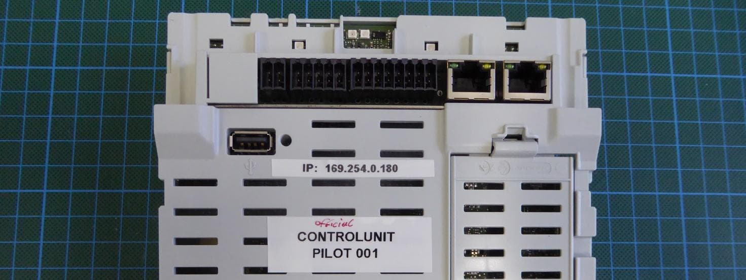
QKWPILOT1
Sep 29, 2024Control and steering unit for solar inverters
Equipment Class
JAB - Part 15 Class B Digital Device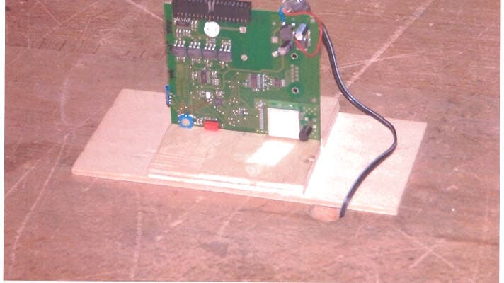
QKWFRF905
Sep 11, 2005Transceiver module
Equipment Class
DSS - Part 15 Spread Spectrum Transmitter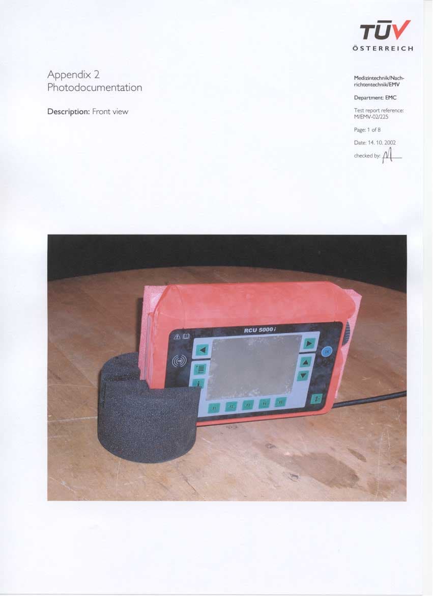
QKWRF5000I
Feb 11, 2003Radio frequency identification system
Equipment Class
DCD - Part 15 Low Power Transmitter Below 1705 kHz