QNT-PT108-00010012442MHz Wireless Modem
REnex Technology Limited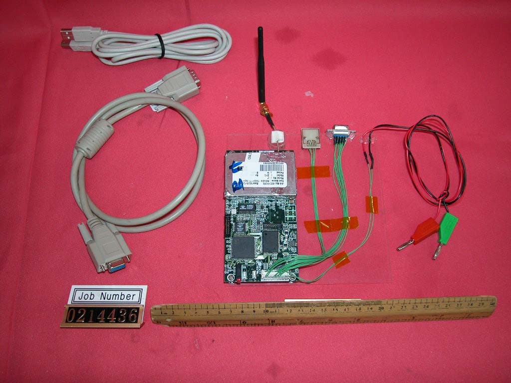
Click to zoom
Application Details
- Equipment Class
- JBP - Part 15 Class B Computing Device Peripheral
- Date of Grant
- Dec 03, 2002
- Application Purpose
- Original Equipment
- Date of Application
- Dec 03, 2002
- Equipment Note
- 2442MHz Wireless Modem
- Company
- REnex Technology Limited
- Country
- Hong Kong
Documents & Files
Document Text
Text extracted from the exhibit documents filed with the FCC. Open a document above to read the original.
Users Manual
- iii - FCC Declaration of Conformity This device complies with Part 15 of the FCC Rules. Operation is subject to the following two conditions: i) this device may not cause harmful interference, and ii) this device must accept any interference received including interference that may cause undesired operation. NOTE: This equipment has been tested and found to comply with the limits for a Class B digital device, pursuant to part 15 of the FCC Rules. These limits are designed to provide reasonable protection against harmful interference in a residential installation. This equipment generates, uses and can radiate radio frequency energy and, if not installed and used in accordance with the instructions, may cause harmful interference to radio communications. However, there is no guarantee that interference will not occur in a particular installation. If this equipment does cause harmful interference to radio or television reception, which can be determined by turning the equipment off and on, the user is encouraged to try to correct the interference by one or more of the following measures: • Reorient or relocate the receiving antenna. • Increase the separation between the equipment and receiver. • Connect the equipment into an outlet on a circuit different from that to which the receiver is needed. • Consult the dealer or an experienced radio/TV technician for help. RS-232 DB9 shielded cable with ferrite must be used with this unit to ensure compliance with the Class B FCC limits. CAUTION: The model number PT-108U has maximum transmitted output power of 0.5 Watt. It is recommended that the transmit antenna be kept at least 20 cm away from nearby persons to satisfy FCC RF exposure requirements. The antenna and transmitter must not be co-located or operating in conjunction with any other antenna or transmitter. 7 3.1 Setting up Connections PT-108U modems are supposed to work properly when they are delivered from REnex. Hence, the only thing users need to do is to make the appropriate application interface connections and power up. The master and slave(s) shall communicate properly. The pin definitions of the application interface are listed in Table 2. Users may connect the RS-232 pins to their equipment according to their practical situations. For any enquiry, please contact REnex for further information. 3.2 Checking the Link After finishing the physical connection setup mentioned above, PT-108U should be ready. If the performance of the communication links is not satisfied or any linking problem is found, the following steps may help you locate the problem. 1. Install DB-9 connectors to the PT-108U modems as described in Section 2.4. 2. Connect each modem to a serial port of a PC. 3. Start a terminal program such as Hyper Terminal (http://www.hilgraeve.com , it may be found in Microsoft Windows OS) for each serial port. Make sure the baud rate and data format settings agree with those of PT-108U. 4. Type characters to the master’s terminal should appear at that of the slave’s and vice versa. 5. The TX LED should flash during transmitting data to the RF link. 6. The RX LED should flash during receiving data from the RF link. 7. Adjust the modem separations and the antenna direction to locate positions with the best performance. 3. Setup PT-108U NOTE 2: PT-108U is highly sensitive to obstacles in its communication path. Make sure the communicating modems are in line-of-sight. Otherwise, the performance would drop significantly. NOTE 3: Antenna height is a critical factor. Try to put the antenna to a position as high as possible.
Cover Letter(s)
Sent: Wednesday, December 04, 2002 7:12 AM To: [email protected] Subject: RE: Renex Technology Limited, FCC ID:QNT-PT108-0001001, AN02T2423 and AN02T2421 Hi Mike, 9) The updated letter is attached. 10) The conducted emission test data is attached for your review. It is applicable for both 15.107 and 15.207 and tested with a typical AC to DC adaptor. 11) The MPE compliance estimation is attached for your review. Please let me if you need other information. Hope this application can be completed by this week as the client call me every day. Thank you. -----Original Message----- From: Mike Kuo [mailto:[email protected]] Sent: Thursday, November 28, 2002 9:14 AM Subject: RE: Renex Technology Limited, FCC ID:QNT-PT108-0001001, AN02T2423 and AN02T2421 Hi Tommy: Question #9: There is no request for confidentiality letter in the attachments. Please provide it. Question #10: Please provide AC line conducted emission test data per 15.107 / 15/207 requirement. Due to nature of the design of this device, please use a typical AC/DC power source to perform the tests. Question #11: MPE compliance can be addressed through estimation ( calculation ). Please provide it. Best Regards Mike Kuo -----Original Message----- Sent: Wednesday, November 27, 2002 2:00 AM To: [email protected] Subject: RE: Renex Technology Limited, FCC ID:QNT-PT108-0001001, AN02T2423 Dear Mike, The user manual has been revised and attached for your review. For the MPE evaluation, refer to Page 19 of Supplement C (Edition 01-01). Transmitters using indoor antennas that operate at 20 cm or more from nearby persons and operating at 4W EIRP (2.4 W ERP) or less at 2450MHz, generally are not expected to exceed MPE limits when nearby persons are 20 cm or more from most antennas. Please let me know what information that I need to provide to you or just an calculation of EIRP is sufficient. Looking forward to hearing from you. Thanks a lot!! Tommy. -----Original Message----- Sent: Wednesday, November 27, 2002 12:26 PM To: 'Mike Kuo' Subject: RE: Renex Technology Limited, FCC ID:QNT-PT108-0001001, AN02T2423 Dear Mike, 1) The spectrum plots are submitted separately and attached in the application of AN02T2421. 2) Two application fee is OK. 3) No, we will discuss with client and amend the user manual. In fact, this is a OEM product, it will be sold to other manufacturer and it needs to apply again after installation. 4) Sorry to missed in the file of "FCC information". Please refer to page ii of the user manual for 15.21. 5) Thanks for your advice, we will ask the client to add the statement. 6) Could you send me the sample or guideline to prepare the MPE evaluation?? 7) The letter is attached for your reference. If you need other information, please feel free to contact me. And have a nice "Thanks Giving Day". Thanks and best regards, Tommy. -----Original Message----- From: Mike Kuo [mailto:[email protected]] Sent: Wednesday, November 27, 2002 11:36 AM Subject: FW: Renex Technology Limited, FCC ID:QNT-PT108-0001001, AN02T2423 -----Original Message----- From: CERTADM Sent: Tuesday, November 26, 2002 7:35 PM To: '[email protected]' Subject: Renex Technology Limited, FCC ID:QNT-PT108-0001001, AN02T2423 Notice_content ------------- Question #1:Please provide 15.247 portion of test data. The test report file does not contain any spectrum plots. Question #2: You requested this application to be reviewed as composite device ( JBP: Personal Computer peripheral and DTS-Digital Transmission System ). There will be two TCB application fee to this composite device. Please confirm. Question #3: In the user manual, it mentioned that this device shall be installed by professional personnel. This grant will be limited to " Professional installation required ". Please confirm. Question #4: User Manual does not include information required under section 15.21 of FCC rules. Please provide revised user manual. Question #5: RF exposure information does not fully comply with FCC guideline. Please include the following wordings " The antenna and transmitter must not be co-located or operating in conjunction with any other antenna or transmitter. Question #6: Please provide MPE evaluation for mobile application. Question #7: Request for confidentiality box is checked on TCB application form. Please provide request for confidentiality letter. Question #8: Since there is not technical data , technical review has not yet completed. Best Regards Mike Kuo / TCB Certifier The items indicated above must be submitted before processing can continue on the above referenced application. Failure to provide the requested information within 60 days of the original e-mail date may result in application dismissal and forfeiture of the filing fee. Also, please note that partial responses increase processing time and should not be submitted. Any questions about the content of this correspondence should be directed to the e-mail address listed below the name of the sender.
External Photos
External photos FCC ID: QNT-PT108-0001001
Internal Photos
Internal photos FCC ID: QNT-PT108-0001001 Assembly (View 1) Assembly (View 2) Internal photos FCC ID: QNT-PT108-0001001 Main PCB comp side (view 1) Main PCB comp side (view 2) Internal photos FCC ID: QNT-PT108-0001001 Main PCB solder side Oscillator PCB comp side
Test Report
• The test results reported in this report shall refer only to the sample actually tested and shall not refer or be deemed to refer to bulk from which such a sample may be said to have been obtained. • This report shall not be reproduced except in full without prior authorization form Giant Electronics Limited Limited FCC ID: QNT-PT108-0001001 Intertek Testing Services Hong Kong Ltd. 2/F., Garment Centre, 576 Castle Peak Road, Kowloon, Hong Kong. Tel: (852) 2173 8888 Fax: (852) 2741 1693 Renex Technology Limited Application For Certification 2.4GHz Spread Spectrum Wireless Modem (FCC ID: QNT-PT108-0001001) WO# 0214436 TL/Ann Choy November 13, 2002 INTERTEK TESTING SERVICE FCC ID: QNT-PT108-0001001 i LIST OF EXHIBITS INTRODUCTION EXHIBIT 1: Summary of Tests EXHIBIT 2: General Description EXHIBIT 3: System Test Configuration EXHIBIT 4: Measurement Results EXHIBIT 5: Equipment Photographs EXHIBIT 6: Product Labelling EXHIBIT 7: Technical Specifications EXHIBIT 8: Instruction Manual INTERTEK TESTING SERVICE FCC ID: QNT-PT108-0001001 ii MEASUREMENT/TECHNICAL REPORT Renex Technology Limited - MODEL: PT-108U FCC ID: QNT-PT108-0001001 This report concerns (check one) Original Grant X Class II Change Equipment Type: DSS-Part 15 Spread Spectrum Transmitter and Class B Personal Computer Peripheral Deferred grant requested per 47 CFR 0.457(d)(1)(ii)? Yes No X If yes, defer until : date Company Name agrees to notify the Commission by: date of the intended date of announcement of the product so that the grant can be issued on that date. Transition Rules Request per 15.37? Yes No X If no, assumed Part 15, Subpart C for intentional radiator - the new 47 CFR [08-20-02 Edition] provision. Report prepared by: Tommy Leung Intertek Testing Service 2/F., Garment Centre, 576 Castle Peak Road, Kowloon, Hong Kong. Phone: 852-2173-8538 Fax: 852-2741-1693 INTERTEK TESTING SERVICE FCC ID: QNT-PT108-0001001 iii Table of Contents 1.0 Summary of test results ...................................................................................................... 1 2.0 General Description..................................................................................................................2 2.1 Product Description .................................................................................................................4 2.2 Related Submittal(s) Grants .....................................................................................................5 2.3 Test Methodology....................................................................................................................5 2.4 Test Facility.............................................................................................................................5 3.0 System Test Configuration .......................................................................................................7 3.1 Justification ..............................................................................................................................7 3.2 EUT Exercising Software.........................................................................................................7 3.3 Support Equipment List and Description ..................................................................................8 3.4 Equipment Modification...........................................................................................................9 4.0 Measurement Results..............................................................................................................11 4.1 Maximum Conducted Output Power at Antenna Terminals....................................................11 4.2 Minimum 6dB RF Bandwidth ................................................................................................12 4.3 Maximum Power Density............................................................................................................. 13 4.4 Out of Band Conducted Emissions .............................................................................................. 14 4.5 Out of Band Radiated Emissions ............................................................................................15 4.6 Transmitter Radiated Emissions in Restricted Bands..............................................................15 4.7 Field Strength Calculation......................................................................................................16 4.8 Radiated Emission Configuration Photograph ........................................................................... 17 4.9 Radiated Emission Data ........................................................................................................18 4.10 Radiated Emission from Digital Section of Transmitter and Class B Personal Computer Peripheral..................................................................................................................................... 20 4.11 Transmitter Duty Cycle Calculation and Measurements.......................................................22 5.0 Equipment Photographs .........................................................................................................24 6.0 Product Labelling....................................................................................................................26 7.0 Technical Specifications ..........................................................................................................28 8.0 Instruction Manual ....................................................................................................................... 30 INTERTEK TESTING SERVICE FCC ID: QNT-PT108-0001001 iv List of attached file Exhibit type File Description filename Test Report Test Report report.doc Operation Description Technical Description descri.pdf Test Setup Photo Radiated Emission config photos.doc Test Report 6 dB Bandwidth Plot 6dB.pdf Test Report Maximum Power Density Plot powden.pdf Test Report Out…
Text truncated - open the document above for the full version.
Test Setup Photos
The Worst Case Configuration Photographs FCC ID: QNT-PT108-0001001 Radiated Emission Front View Rear View
Contact Information
Applicant
Yiguang Ma(VP of Engineering)
Test Firm
Intertek Testing Services Hong KongBilly Chow
Technical Specifications
| # | Rule Parts | Frequency Range | Power Output |
|---|---|---|---|
| 1 | 15B | - | - |
Other Applications from REnex Technology Limited
QNT-PT2400GS00-A
May 29, 2007Spread Spectrum Transmitter
Equipment Class
DSS - Part 15 Spread Spectrum Transmitter
QNT-PT2400GS20-A
May 29, 2007Spread Spectrum Transmitter
Equipment Class
DSS - Part 15 Spread Spectrum Transmitter
QNT-PT209-0104003
Nov 29, 20042.4GHz DSSS Wireless Modem
Equipment Class
DTS - Digital Transmission System
QNT-PT209-0104001
Nov 29, 20042.4GHz DSSS Wireless Modem
Equipment Class
DTS - Digital Transmission System
QNT-PT209-0104002
Nov 29, 20042.4GHz DSSS Wireless Modem
Equipment Class
DTS - Digital Transmission System