QO86021RWall Unit (2.4GHz Transceiver)
Radio Thermostat Company of America, Inc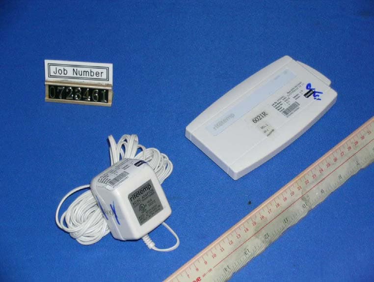
Click to zoom
Application Details
- Equipment Class
- DXT - Part 15 Low Power Transceiver, Rx Verified
- Date of Grant
- Dec 17, 2007
- Application Purpose
- Original Equipment
- Date of Application
- Dec 17, 2007
- Equipment Note
- Wall Unit (2.4GHz Transceiver)
- Frequency Range
- 2405.00000000 - 2480.00000000
- Country
- United States
Documents & Files
Document Text
Text extracted from the exhibit documents filed with the FCC. Open a document above to read the original.
Users Manual
• Your thermostat is a precise instrument, take care. • Turn off electricity to the appliance before installing or servicing thermostat or any part of the system. • Do not turn electricity back on until work is completed. • Do not short (jumper) across electric terminals at control on furnace or air conditioner to test the system. This will damage the thermostat or Wall Unit and void your warranty. • All wiring must conform to local codes and ordinances. • This Thermostat/Wall Unit is designed for use with 24 volt AC and millivolt systems. The Wall Unit should be limited to a maximum of 1.0 amps; higher amperage may cause damage to the Wall Unit. Caution Front Cover Back Cover 2nov07 draft 2 28oct07 initial rel 1711-002 Install guide 6021z Customer Support: 877-505-2353 or Visit our website www.ritetemp-thermostats.com Printed in China Installation 8082 RESET MENU PROGRAM Front cover pg 1 pg 2 Instruction Book Concept First page spread C A U T I O N Your thermostat is a precise instrument. Please handle it with care. Turn off electricity to the appliance before installing or servicing thermostat or any part of the system. Do not turn electricity back on until work is completed. Do not short (jumper) across electric terminals at control on furnace or air conditioner to test the system . This will damage the thermostat and void your warranty. All wiring must conform to local codes and ordinances. This thermostat is designed for use with 24 volt AC and millivolt systems. The thermostat should be lim ited to a maxim um of 1.0 amps; higher amperage may cause damage to the thermostat. On replacement installations, mount the new thermostat in place of the old one if possible. On new Installations, follow the guidelines listed below. Locate the thermostat on an inside wall, about 5 ft. (1.5m) above the floor, and in a room that is used often. Do not install it where there are unusual heating conditions, such as: in direct sunlight; near a lamp, radio, television, radiator register, or fireplace; near hot water pipes in a wall; near a stove on the other side of a wall. Good 5ft. (1.5m) PG 2 Installation 8082 1 Location Caution Tools To avoid electrical shock and to prevent damage to the furnace, air conditio ner, and therm ostat, disconnect the power supply before beginning work. This can be done at the circuit breaker, or at the appliance. On replacement installations, mount the new thermostat in place of the old one if possible. On new Installations, follow the guidelines listed below. Locate the thermostat on an inside wall, about 5 ft. (1.5m) above the floor, and in a room that is used often. Do not install it where there are unusual heating conditions, such as: in direct sunlight; near a lamp, radio, television, radiator register, or fireplace; near hot water pipes in a wall; near a stove on the other side You will need #1 Phillips screwdriver (small) and Drill with 3/16-in. (4.8mm) bit for this installation. ENGLISH HEAT COOL 2STG FAN BINDING LOW BATT HEAT HEAT COOL OFF FAN AUTO ON NORMAL SAVE ENERGY HEAT COOL 2STG FAN BINDING LOW BATT HEAT HEAT COOL OFF FAN AUTO ON NORMAL SAVE ENERGY Product Name: 6021z Document Title: Install Guide ENG Document Type Code: IBIE Part Number: 711-002 Install Wall Unit Caution Tools To avoid electrical shock and to prevent damage to the furnace, air conditioner, and thermostat wall unit, disconnect the power supply before beginning work. This can be done at the circuit breaker, or at the appliance. The 6021z Wireless Thermostat system is made of two parts - The Thermostat and the Wall Unit. You will first install the Wall Unit and then configure the Thermostat. Replacement installations - You can mount the Wall Unit in place of the old thermostat. Remember the "C" power wire is required for operation this supplies 24VAC to the transmitter in the Wall Unit and allows continuous communication with the Thermostat. Because the 6021z system is wireless it is easiest to mount the Wall Unit next to the HVAC unit in the basement attic or HVAC closet even in a replacement installation. New Installation or Change of location from Wall to HVAC We recommend the WALL UNIT unit be installed in the same area and close to the HVAC location so it can be wired directly to the HVAC's thermostat terminals. The WALL UNIT unit has no temperature sensing devices but still should not be mounted outside or where it would be exposed to weather conditions. It can be mounted at any angle on the wall. 24VAC Power - The Wall Unit REQUIRES the HVAC 24VAC power wire (C) to work. If the C wire is not available at a previous wall installation, the C wire must be added or the Wall Unit should be mounted at the HVAC location where the C wire power is always available. You will need a small Phillips screwdriver and possibly a drill with 3/16-in. (4.8mm) bit for mounting the Wall Unit. PG 1 fold and staple PG 2 Install guide 6021z HEAT COOL 2STG FAN BINDING LOW BATT Remove old unit Prepare wires IMPORTANT : LABEL ALL WIRES BEFORE DISCONNECTING THEM! If you are going to place the Wall Unit in the same location as the old thermostats... ï Switch electricity to the furnace and air conditioner OFF; then proceed with the following steps. ï Remove cover from old thermostat. Most are snap-on types and simply pull off. Some have locking screws on the side or front. These must be loosened. Note the letters printed near the terminals. Attach labels (enclosed) to each wire for identification. ï Label the wires one at a time. You must label all the wires before you proceed. With all wires labeled, remove them from the old unit. ï Make sure the wires do not fall back inside the wall. You can wind them around a pencil to keep them from falling. ï Loosen all screws on the old thermostat and remove it from the wall. ï Fill wall opening with non-combustible insulation to prevent drafts. If you are going to locate the Wall Unit at the HVAC... ï Switch electricity to the furnace and air conditioner OFF; then pr…
Text truncated - open the document above for the full version.
Block Diagram
not provide for 6021R
External Photos
External Photo FCC ID : QO86021R External Photo - front External Photo - rear
ID Label/Location Info
BINDING LOW BATT . HEAT COOL 2STG FAN 48.0 1 0 . 0 IC:4714A-6021R MADE IN CHINA Model : 6021Z FCC ID :QO86021R This device complies with Part 15 of the FCC Rules. Operation is subject to the following two conditions: (1) This device may not cause harmful interference, and (2) This device must accept any interference received, including interference that may cause undesired operation. IC:4714A-6021R MADE IN CHINA Model : 6021Z FCC ID :QO86021R This device complies with Part 15 of the FCC Rules. Operation is subject to the following two conditions: (1) This device may not cause harmful interference, and (2) This device must accept any interference received, including interference that may cause undesired operation. IC:4714A-6021R MADE IN CHINA Model : 6021Z FCC ID :QO86021R This device complies with Part 15 of the FCC Rules. Operation is subject to the following two conditions: (1) This device may not cause harmful interference, and (2) This device must accept any interference received, including interference that may cause undesired operation. IC:4714A-6021R MADE IN CHINA Model : 6021Z FCC ID :QO86021R This device complies with Part 15 of the FCC Rules. Operation is subject to the following two conditions: (1) This device may not cause harmful interference, and (2) This device must accept any interference received, including interference that may cause undesired operation. 2 : 1 Model : 6021Z Factory Issue Date: 30-10-07 FCC ladel & IC identification label artwork location. (Revise 1) The label is affixed on the side of the front cabinet and pcb cover .(Main Unit)
Internal Photos
Internal Photo FCC ID : QO86021R Internal Photo - 1 Internal Photo - 2 Internal Photo FCC ID : QO86021R Internal Photo - 3 Internal Photo - 4 Internal Photo FCC ID : QO86021R Internal Photo - 5
Operational Description
6021Z Technical description This product is a thermostat with wireless control. It is a transceiver operating at 2.4GHz ISM band. The Thermostat is powered by 2 × “AAA”, 2 × “C” and output 6VDC adaptor. The Wall Unit is powered by 2 × AAA and output 24VAC adaptor. The 2.4GHz RF transceiver function is provided by EM250 chips (MD1/ MM1). The RX architecture of the chip is based on a low-IF, superheterodyne receiver. It utilizes differential signal paths to minimize noise interference. The input RF signal is mixed down to the IF frequency of 4MHz by I and Q mixers. The output of the mixers is filtered and combined prior to being sampled by a 12Msps ADC. The EM250 transmitter utilizes both analog circuitry and digital logic to produce the O-QPSK modulated signal. The area-efficient TX architecture directly modulates the spread symbols prior to transmission. The differential signal paths increase noise immunity and provide a common interface for the external balun. For the Wall Unit, the received data will be processed by RF IC (MD1) and the sampled data will transfer the relay driver IC (U3) that will control the relays ON/ OFF. At the same time, the RC IC (MD1) will transmit a confirmation signal to the corresponding Thermostat. For the Thermostat, the thermo-sensor (TC1) will monitor the temperature. When the target temperature is reached, the MCU (U1) will send the command with RF IC (MM1) and get back confirmation that the command was received and implemented by the corresponding Wall Unit. The external components of the RF path consist of a Balun circuit (composed of L1, L2, L3, C1, C2, C3), which is a 50/200 Ohm conversion which stabilizes the load observed by the internal PA across the 2.4GHz ISM band, a harmonic filter circuit (composed of L4, C6, C7), and an antenna. GOLDEN POWER MANUFACTURING LTD. Model: 6021Z The Channel frequency of 802.15.4 (ZigBee) as below: Channel Frequency (MHz) 11 2405 12 2410 13 2415 14 2420 15 2425 16 2430 17 2435 18 2440 19 2445 20 2450 21 2455 22 2460 23 2465 24 2470 25 2475 26 2480 wireless semiconductor solutions EM250 Single-Chip ZigBee/802.15.4 Solution Integrated 2.4GHz, IEEE 802.15.4-compliant transceiver: Robust RX filtering allows co-existence with IEEE 802.11g and Bluetooth devices - 99dBm RX sensitivity (1% PER, 20byte packet) + 3dBm nominal output power Increased radio performance mode (boost mode) gives - 100dBm sensitivity and + 5dBm transmit power Integrated VCO and loop filter Integrated IEEE 802.15.4 PHY and lower MAC with DMA Integrated hardware support for Packet Trace Inter-face for InSight Development Environment Provides integrated RC oscillator for low power opera- tion Supports optional 32.768kHz crystal oscillator for higher accuracy needs 16-bit XAP2b microprocessor Integrated memory: 128kB of Flash 5kB of SRAM Configurable memory protection scheme Two sleep modes: Processor idle Deep sleep—1.0μA (1.5μA with optional 32.768kHz oscillator enabled) Seventeen GPIO pins with alternate functions Two Serial Controllers with DMA SC1: I 2 C master, SPI master + UART SC2: I 2 C master, SPI master/slave Two 16-bit general-purpose timers; one 16-bit sleep timer Watchdog timer and power-on-reset circuitry Non-intrusive debug interface (SIF) Integrated AES encryption accelerator Integrated ADC module first-order, sigma- delta converter with 12-bit resolution Integrated 1.8V voltage regulator PacketTrace ADC RF_P,N Program Flash 128kB Data SRAM 5kB SIF_MISO HF OSC LF OSC ADC SIF Internal RC-OSC GPIO multiplexor swtich Chip manager Regulator Bias Interrupt controller RF_TX_ALT_P,N OSCA OSCB OSC32A OSC32B GPIO[16:0] SIF_MOSI SIF_CLK nSIF_LOAD Encryption accelerator IF Always powered XAP2b CPU VREG_OUT Watchdog PA select LNA PA PA DAC MAC + Baseband TX_ACTIVE Sleep timer BIAS_R POR nRESET General purpose timers GPIO registers UART/ SPI/I2C SYNTH Ember Corporation 343 Congress Street Boston MA 02210 USA +1 617.951.0200 www.ember.com 120-0082-000M June 29 , 2007 EM250 120-0082-000M Page 2 General Description The EM250 is a single-chip solution that integrates a 2.4GHz, IEEE 802.15.4-compliant transceiver with a 16-bit XAP2b microprocessor. It contains integrated Flash and RAM memory and peripherals of use to designers of ZigBee-based applications. The transceiver utilizes an efficient architecture that exceeds the dynamic range requirements imposed by the IEEE 802.15.4-2003 standard by over 15dB. The integrated receive channel filtering allows for co-existence with other communication standards in the 2.4GHz spectrum such as IEEE 802.11g and Bluetooth. The inte- grated regulator, VCO, loop filter, and power amplifier keep the external component count low. An optional high performance radio mode (boost mode) is software selectable to boost dynamic range by a further 3dB. The XAP2b microprocessor is a power-optimized core integrated in the EM250. It supports two different modes of operation—System Mode and Application Mode. The EmberZNet stack runs in System Mode with full access to all areas of the chip. Application code runs in Application Mode with limited access to the EM250 resources; this allows for the scheduling of events by the application developer while preventing modification of re- stricted areas of memory and registers. This architecture results in increased stability and reliability of de- ployed solutions. The EM250 has 128kB of embedded Flash memory and 5kB of integrated RAM for data and program storage. The EM250 software stack employs an effective wear-leveling algorithm in order to optimize the lifetime of the embedded Flash. To maintain the strict timing requirements imposed by ZigBee and the IEEE 802.15.4-2003 standard, the EM250 integrates a number of MAC functions into the hardware. The MAC hardware handles automatic ACK transmis- sion and reception, automatic backoff delay, and clear channel assessment for transmission, as well as auto- matic filtering of received packets. In addition, the EM250 allows for true MAC level de…
Text truncated - open the document above for the full version.
Test Report
- The evaluation data of the report will be kept for 3 years from the date of issuance. - This report is for the exclusive use of Intertek's Client and is provided pursuant to the agreement between Intertek and its Client. Intertek's responsibility and liability are limited to the terms and conditions of the agreement. Intertek assumes no liability to any party, other than to the Client in accordance with the agreement, for any loss, expense or damage occasioned by the use of this report. Only the Client is authorized to permit copying or distribution of this report and then only in its entirety. Any use of the Intertek name or one of its marks for the sale or advertisement of the tested material, product or service must first be approved in writing by Intertek. The observations and test results in this report are relevant only to the sample tested. This report by itself does not imply that the material, product, or service is or has ever been under an Intertek certification program. Intertek Testing Services Hong Kong Ltd. 2/F., Garment Centre, 576 Castle Peak Road, Kowloon, Hong Kong. Tel: (852) 2173 8888 Fax: (852) 2785 5487 Website: www.hk.intertek-etlsemko.com Golden Power Manufacturing Ltd. Application For Certification (FCC ID: QO86021R) Transceiver (Wall Unit) 0723461 BH/ SL November 23, 2007 INTERTEK TESTING SERVICES FCC ID: QO86021R i LIST OF EXHIBITS INTRODUCTION EXHIBIT 1: General Description EXHIBIT 2: System Test Configuration EXHIBIT 3: Emission Results EXHIBIT 4: Equipment Photographs EXHIBIT 5: Product Labelling EXHIBIT 6: Technical Specifications EXHIBIT 7: Instruction Manual EXHIBIT 8: Miscellaneous Information INTERTEK TESTING SERVICES FCC ID: QO86021R ii MEASUREMENT/TECHNICAL REPORT Golden Power Manufacturing Ltd. - MODEL: 6021Z FCC ID: QO86021R November 23, 2007 This report concerns (check one:) Original Grant X Class II Change Equipment Type: DXT - Low Power Transceiver, Rx Verified (example: computer, printer, modem, etc.) Deferred grant requested per 47 CFR 0.457(d)(1)(ii)? Yes No X If yes, defer until: date Company Name agrees to notify the Commission by: date of the intended date of announcement of the product so that the grant can be issued on that date. Transition Rules Request per 15.37? Yes No X If no, assumed Part 15, Subpart C for intentional radiator - the new 47 CFR [05-04-07 Edition] provision. Report prepared by: Ho Wai Kin, Ben Intertek Testing Services Hong Kong Ltd. 2/F., Garment Center, 576, Castle Peak Road, Kowloon, Hong Kong. Phone: 852-2173-8505 Fax: 852-2371-0521 INTERTEK TESTING SERVICES FCC ID: QO86021R iii Table of Contents 1.0 General Description............................................................................................ 2 1.1 Product Description ............................................................................................ 2 1.2 Related Submittal(s) Grants ............................................................................... 2 1.3 Test Methodology............................................................................................... 3 1.4 Test Facility........................................................................................................ 3 2.0 System Test Configuration ................................................................................. 5 2.1 Justification ........................................................................................................ 5 2.2 EUT Exercising Software.................................................................................... 5 2.3 Special Accessories ........................................................................................... 5 2.4 Equipment Modification ...................................................................................... 6 2.5 Measurement Uncertainty .................................................................................. 6 2.6 Support Equipment List and Description ............................................................. 6 3.0 Emission Results ................................................................................................ 8 3.1 Field Strength Calculation................................................................................... 9 3.2 Radiated Emission Configuration Photograph................................................... 10 3.3 Radiated Emission Data ................................................................................... 11 3.4 Conducted Emission Configuration Photograph................................................ 13 3.5 Conducted Emission Data .....................................................................................14 4.0 Equipment Photographs ................................................................................... 16 5.0 Product Labelling.............................................................................................. 18 6.0 Technical Specifications ................................................................................... 20 7.0 Instruction Manual ............................................................................................ 22 8.0 Miscellaneous Information ............................................................................... 24 8.1 Bandedge Plot ................................................................................................. 25 8.2 Discussion of Pulse Desensitization.................................................................. 26 8.3 Emissions Test Procedures .............................................................................. 27 INTERTEK TESTING SERVICES FCC ID: QO86021R iv List of attached file Exhibit type File Description filename Test Report Test Report report.pdf Operation Description Technical Description descri.pdf Test Setup Photo Radiated Emission radiated photos.doc Test Setup Photo Conducted Emission conducted photos.doc Test Report Conducted Emission Test Result conducted.pdf Test Report Bandedge Plot be.…
Text truncated - open the document above for the full version.
Test Report
Report No.: 0723461 Tx & Rx Mode AC Mains “L” Ctrl No.: N/A PAGE 1 Report No.:0723461 Scan Settings (1 Range) |--------- Frequencies -----------||----------- Receiver Settings ------------| Start Stop Step IF BW Detector M-Time Atten Preamp OpRge 150k 30M 5k 10k PK+AV 10ms AUTO LN OFF 60dB Final Measurement: x QP / + AV Meas Time: 1 s Subranges: 16 Acc Margin: 20dB Transducer No. Start Stop Name 2 1 9k 30M EW0700 12 9k 30M EW0090 0 10 20 30 40 50 60 70 80 90 dBuV 100 0.15 MHz 30 110 F15Q F15A Report No.: 0723461 Tx & Rx Mode AC Mains “L” Ctrl No.: N/A Report No.:0723461 Scan Settings (1 Range) |--------- Frequencies -----------||----------- Receiver Settings ------------| Start Stop Step IF BW Detector M-Time Atten Preamp OpRge 150k 30M 5k 10k PK+AV 10ms AUTO LN OFF 60dB Final Measurement Results: Frequency QP Level QP Limit Delta MHz dBuV dBuV dB 0.15000 42.0 66.0 -24.0 Frequency AV Level AV Limit Delta MHz dBuV dBuV dB no Results * limit exceed Report No.: 0723461 Tx & Rx Mode AC Mains “N” Ctrl No.: N/A PAGE 1 Report No.:0723461 Scan Settings (1 Range) |--------- Frequencies -----------||----------- Receiver Settings ------------| Start Stop Step IF BW Detector M-Time Atten Preamp OpRge 150k 30M 5k 10k PK+AV 10ms AUTO LN OFF 60dB Final Measurement: x QP / + AV Meas Time: 1 s Subranges: 16 Acc Margin: 20dB Transducer No. Start Stop Name 2 1 9k 30M EW0700 12 9k 30M EW0090 0 10 20 30 40 50 60 70 80 90 dBuV 100 0.15 MHz 30 110 F15Q F15A Report No.: 0723461 Tx & Rx Mode AC Mains “N” Ctrl No.: N/A Report No.:0723461 Scan Settings (1 Range) |--------- Frequencies -----------||----------- Receiver Settings ------------| Start Stop Step IF BW Detector M-Time Atten Preamp OpRge 150k 30M 5k 10k PK+AV 10ms AUTO LN OFF 60dB Final Measurement Results: Frequency QP Level QP Limit Delta MHz dBuV dBuV dB 0.15500 42.8 65.7 -22.9 0.21000 36.3 63.2 -26.9 Frequency AV Level AV Limit Delta MHz dBuV dBuV dB no Results * limit exceed
Test Report
Job No.: 0723461 (Plot A) Delta Measurement = Radiated Emission – 42.8dB = 90.9dB μ V/m – 42.8dB = 48.1dB μ V/m Job No.: 0723461 (Plot B) Delta Measurement = Radiated Emission – 40.04dB = 88.6dB μ V/m – 40.04dB = 48.56dB μ V/m
Test Setup Photos
Test Setup FCC ID : QO86021R Radiated - front Radiated - rear
Test Setup Photos
Test Setup FCC ID : QO86021R Conduct Photo - 1 Conduct Photo - 2 Test Setup FCC ID : QO86021R Conduct Photo - 3
Contact Information
Applicant
Kathy Little
Technical Contact
Intertek Testing Services Hong Kong Ltd.Billy Chow
[email protected]852-2173-8528
2/F., Garment Centre, · Kowloon · Hong Kong
Non-Technical Contact
Intertek Testing Services Hong Kong Ltd.Billy Chow
[email protected]852-2173-8528
Test Firm
Intertek Testing Services Hong KongBilly Chow
Technical Specifications
| # | Rule Parts | Frequency Range | Power Output |
|---|---|---|---|
| 1 | 15C | 2.40 GHz - 2.48 GHz | - |
Other Applications from Radio Thermostat Company of America, Inc

QO8-CT102R1
Nov 03, 2015Thermostat
Equipment Class
DXX - Part 15 Low Power Communication Device Transmitter
QO8-CT110R1
Jun 09, 2015Thermostat
Equipment Class
DXX - Part 15 Low Power Communication Device Transmitter
QO8-USZW5202
Mar 18, 2014Z-Wave USNAP module
Equipment Class
DXX - Part 15 Low Power Communication Device Transmitter
QO8-CT101R1
Jul 26, 2012Low Power Communication Device Transmitter:908.4MHz transmitter
Equipment Class
DXX - Part 15 Low Power Communication Device Transmitter
QO8-CT100R1
Jan 12, 2012Z-WAVE COMMUNICATING THERMOSTAT
Equipment Class
DXX - Part 15 Low Power Communication Device Transmitter