QOS-RXNANODIV915 MHz Receiver Module (Transceiver)
TBS Avionics Limited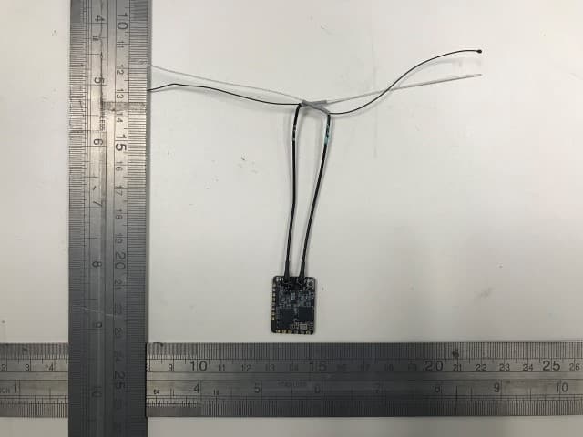
Click to zoom
Application Details
- Equipment Class
- DSS - Part 15 Spread Spectrum Transmitter
- Date of Grant
- May 12, 2020
- Application Purpose
- Original Equipment
- Date of Application
- May 12, 2020
- Equipment Note
- 915 MHz Receiver Module (Transceiver)
- Frequency Range
- 902.75000000 - 927.25000000
- Company
- TBS Avionics Limited
- Country
- China
Documents & Files
Document Text
Text extracted from the exhibit documents filed with the FCC. Open a document above to read the original.
Users Manual
TBS CROSSFIRE R/C SystemRevision 2020-02-21 Adaptive Long Range Remote Control System The TBS CROSSFIRE (XF) system is a R/C link system made for FPV enthusiasts. It features unheard of range without sacrificing basic functionality such as being immune to interference from onboard equipment, low latency control or two-way communications including telemetry functionality. Key features •Long range, adaptive and robust remote control system for your aircraft •Immune to on-board noise •Two-way communication link with real-time link vitals and telemetry •Self-healing frequency hopping link •Receiver beacon mode to recover your downed aircraft •Super easy binding and configuration via built-in OLED display, OpenTX LUA or TBS TANGO remote •Low latency control for perfect immersive feeling •Free output mappable 8 output diversity with integrated backup battery or super tiny receiver ( 4g weight only ) both with up to 12 channel PPM •Ability to fly with multiple friends at the same time (10 or more) •Dynamic self-selecting or selectable RF power from 10mW to 1W (local restrictions apply) •Dedicated head-tracking input option for full FPV immersion •Transmitter LED shows link health, OLED display for built in configuration •Expansion port for future feature support 1 Table of content Attention Drone Racing Environment Crossfire LED Color Coding Overview Setup Connecting CROSSFIRE Standard Transmitter to radio Using JR-adapter Using Hitec/Graupner/JR-cable Using Futaba-cable Using custom PPM cable CRSF with other radios Connecting CROSSFIRE Micro transmitter to radio Push button functionality Connecting CROSSFIRE Diversity receiver Connecting CROSSFIRE Micro receiver Connecting CROSSFIRE Nano receiver Binding Auto bind Head-tracking Set failsafe BST Connectivity with TBS equipment Controlling UNIFY PRO VTX with SmartAudio Antenna Operation Status display Up- and downlink status Find mode Direction finder How does find mode work Testing find mode 2 Preparations Simulating flight Simulating a Crash Search and rescue Link regained Transmitter LED status indicator Receiver LED status indicator Real-time telemetry using app link Configuration Standard transmitter configuration Micro transmitter configuration Receiver PWM or PPM servo output Receiver SBUS output Receiver RSSI or/and LQ output Serial bridge MAVLink MAVLink APM Disable telemetry CRSF DSMX SmartAudio Transmission power Dynamic transmission power Transmission frequency Operating modes RF Profiles MyVTX CRSF Connectivity with flight controller (COLIBRI) Minimum requirements Wiring layout 3 Setting up radio for CRSF Setting up receiver for CRSF Configuring BetaFlight for CRSF protocol Discovering telemetry data sensors Configuration of CORE PRO / CROSSFIRE RX with LUA Scripts or the TBS TANGO Requirements Setup Telemetry Firmware upgrade Installing TBS Agent Emergency update FAQ Good practices FCC statement FCC ID of TBS Crossfire Products 4 Specifications Type: Long Range Two-Way Remote Control System Band: Europe: 868 MHz SRD Band America: 915 MHz ISM Band RF power Radio Signal & Telemetry downlink: Micro TX: Selectable 25mW and 100mW (250mW with FW 2.40 or later) Standard TX: Selectable 10mW to 500mW, additional 1W available with external power connected via XT30 socket Diversity, Micro and Nano RX: 40mW Receiver sensitivity: Up to -130dBm Antenna: TX: 1x omnidirectional dipole antenna RX: 2x omnidirectional dipole antennas, flexible antenna (Micro and Nano RX) R/C Channels: 8 (Diversity)/ 4(6) (Micro/Nano RX) PWM (freely mappable ) or up to 12-channel PPM stream outputs, standard 2.54mm servo connectors Radio compatibility: Any radio with PPM stream output ( absolute max. ratings: -0.3V - 15V ) JR Adapter for easy install on JR, FrSky and similar radios Interface: Micro TX: RGB LED light, push button, configuration via CRSF (TBS TANGO, OpenTX ect. ) Standard TX: 1.3-inch OLED display and joystick for configuration, binding and link stats, real-time telemetry link to any computer, tablet or phone and Micro-USB for firmware upgrade Recovery mode: Diversity RX: Beacon-mode, receiver backup LiPo battery - operating time of approx. 2 days Failsafe: Pre-set servo positions or stops outputting servo pulse - selectable in configuration menu or via push button Operating range: Variable depending on output power and radio environment Input power: TX: +3.5 to 12.6V via RC or HT 3-pin input connector, External 2S to 3S LiPo via XT30 connector (standard RX only) RX: +4.5V to 8.4V All reverse-polarity protected Power consumption: TX: 1.1W, at 25mW TX: 3.2W, at Max Tx power output Diversity RX: 1.5W / Micro/Nano RX: 1W Ports: Diversity RX: 1x BST (the CROSSFIRE RX does not power the BST line), 8x Servo connectors - Micro RX: V1: 1x Servo, 1x BST / V2: 4x Servo, 1x BST - Nano RX: 2x Pin-headers for 1x BST and 4x Servo Working temperature: 0 - 40°C Size: Standard TX: 150 x 80 x 20 mm, Micro TX: 73 x 56 x 35 mm Diversity RX: 30 x 50 x 12 mm, Micro RX: 40 x 14 x 9.5mm Weight: Micro TX: 38 grams Standard TX: 340 grams, Diversity RX: 25 grams, Micro RX: 3.2 grams Kit contents: 1x TBS CROSSFIRE TX transceiver unit, 1x TBS CROSSFIRE RX transceiver unit, 1x JR-adapter module, 1x Futaba-cable, 1x JR-cable, 1x custom-cable, 1x XT30 cable 5 Attention A general rule for RC aircrafts is that they must be controlled always under sight of view, check your RC regulation to keep up to date with regulations. Drone Racing Environment Crossfire Firmware V3.23 and above incorporates Racing Spec Firmware designed for race directors to effectively manage power output on CROSSFIRE for drone racing. When using TBS CROSSFIRE control link, it is a requirement that all pilots use exactly the same power output. Use of CROSSFIRE has the same requirement as management of video transmission power output when it comes to racing. Recommended power output is generally 100mW, however in some countries the maximum will be 25mW. Please check your countries regulations. The New LED Color Sy…
Text truncated - open the document above for the full version.
External Photos
Test Report No.: 50159780 001 Appendix 3 Page 1 of 2 Appendix 3 EUT External Photos Test Report No.: 50159780 001 Appendix 3 Page 2 of 2 External View
Internal Photos
Test Report No.: 50159780 001 Appendix 4 Page 1 of 2 Appendix 4 EUT Internal Photos Test Report No.: 50159780 001 Appendix 4 Page 2 of 2 Internal View Internal View
RF Exposure Info
Test Report No.: 50159780 001 Appendix 5 Page 1 of 2 Appendix 5 RF Exposure Information Test Report No.: 50159780 001 Appendix 5 Page 2 of 2 Maximum transmitter power: Frequency (MHz) Maximum peak output power (dBm) Duty Cycle % Average Output power(mW) Separation Distance (mm) 902.75 12.93 30% 5.89 5 914.75 13.15 30% 6.20 5 927.25 13.17 30% 6.22 5 Duty Cycle Calculation Hopping rate = 50 Hz Transmitter on time per hop = 6ms Duty cycle = 6/20 * 100 = 30% According to KDB 447498 D01: These test exclusion conditions are based on source-based time-averaged maximum conducted output power of the RF channel requiring evaluation. The 1-g and 10-g SAR test exclusion thresholds for 100 MHz to 6 GHz at test separation distances ≤50 mm are determined by: [(max. power of channel, including tune-up tolerance, mW)/(min. test separation distance, mm)] · [√f(GHz)] ≤3.0 for 1-g SAR and ≤7.5 for 10-g extremity SAR,24 where • f(GHz) is the RF channel transmit frequency in GHz • Power and distance are rounded to the nearest mW and mm before calculation25 • The result is rounded to one decimal place for comparison • 3.0 and 7.5 are referred to as the numeric thresholds in the step 2 below Result: (5.89/5)*√0.90275 = 1.119 <3.0 (6.20/5)*√0.91475 = 1.167 <3.0 (6.22/5)*√0.92725 = 1.198 <3.0 Conclusion: No SAR is required.
Test Report
Produkte Products 3-4, 11/F., Fou Wah Industrial Building, 10-16 Pun Shan Street, Tsuen Wan, N.T., Hong Kong Tel.: +852 2192 1000 Fax: +852 2192 1001 Email [email protected] Web: www.tuv.com Test Report No.: 50159780 001 Auftrags-Nr.: Order No.: 144188446 Seite 1 von 17 Page 1 of 17 Kunden-Referenz-Nr.: Client Reference No.: N/A Auftragsdatum: Order date: 27.06.2018 Auftraggeber: Client: TBS Avionics Limited 9/F, Tungtex Building, 203 Wai Yip Street, Kwun Tong, Hong Kong, China Test item: 915 MHz Receiver Module (Transceiver) Bezeichnung / Typ-Nr.: Identification / Type No.: Crossfire Nano Diversity RX Auftrags-Inhalt: Order content: FCC Certification Test specification: FCC Part 15 Subpart C ANSI C63.10-2013 Wareneingangsdatum: Date of receipt: 10.01.2020 Test sample No.: A001055945-001 Testing period: 20.01.2020 - 25.02.2020 Place of testing: Hong Kong Testing laboratory: Kong Ltd. Test result*: Pass tested by: kontrolliert von / reviewed by: 24.03.2020 Benny Lau / Senior Project Manager24.03.2020 Sharon Li / Senior Unit Manager Datum Date Name / Stellung Name / Position Unterschrift Signature Datum Date Name / Stellung Name / Position Unterschrift Signature Sonstiges / Other: FCC ID: QOS-RXNANODIV Condition of the test item at delivery: Test item complete and undamaged * Legende: 1 = sehr gut 2 = gut 3 = befriedigend 4 = ausreichend 5 = mangelhaft N/A = nicht anwendbar N/T = nicht getestet Legend: 1 = very good 2 = good 3 = satisfactory 4 = sufficient 5 = poor P(ass) = passed a.m. test specification(s) F(ail) = failed a.m. test specification(s) N/A = not applicable N/T = not tested t This test report only relates to the a. m. test sample. Without permission of the test center this test report is not permitted to be duplicated in extracts. This test report does not entitle to carry any test mark. FCC_15.247_DSS_v2.0 Test Report No.: 50159780 001 Date: 24.03.2020 Page 2 of 17 Table of Content Page .......... 1 ............... 2 Product information....................................................................................................... 4 Manufacturers declarations ....................................................................................................................... 4 Product function and intended use ........................................................................................................... 4 Submitted documents ................................................................................................................................. 4 Independent Operation Modes .................................................................................................................. 4 Related Submittal(s) Grants ....................................................................................................................... 4 Remark ......................................................................................................................................................... 4 Test Set-up and Operation Mode .................................................................................. 5 Principle of Configuration Selection ......................................................................................................... 5 Test Operation and Test Software ............................................................................................................. 5 Special Accessories and Auxiliary Equipment ......................................................................................... 5 Countermeasures to achieve EMC Compliance ....................................................................................... 5 Test Methodology .......................................................................................................... 6 Radiated Emission ...................................................................................................................................... 6 Field Strength Calculation .......................................................................................................................... 6 Test Setup Diagram ....................................................................................................... 7 Test Facility .................................................................................................................... 9 Test Laboratory Information ...................................................................................................................... 9 List of Test and Measurement Instruments ............................................................... 10 Measurement Uncertainty ........................................................................................... 11 ............................................................ 12 ............................................................. Pass ............... 12 ............................................................. Pass ............... 12 ..................................................... N/A ............... 12 ............................................................. Pass ............... 12 ................................................................ Pass ............... 13 ...................................................... Pass ............... 13 ..................................................... Pass ............... 14 ime) .............................................. Pass ............... 14 FCC_15.247_DSS_v2.0 Test Report No.: 50159780 001 Date: 24.03.2020 Page 3 of 17 .............................................................. Pass ............... 15 ..................................................... Pass ............... 15 .......................................................... Pass ............... 15 ......................................................... Pass ............... 15 .................................................... Pass ............... 16 ncy Bands .............................. Pass .............…
Text truncated - open the document above for the full version.
Test Setup Photos
Test Report No.: 50159780 001 Appendix 2 Page 1 of 2 Appendix 2 Test Setup Photos Test Report No.: 50159780 001 Appendix 2 Page 2 of 2 Set-up for Radiated Emission
Contact Information
Applicant
Raphael Pirker(Manager)
Test Firm
TUV Rheinland Hong Kong LimitedSharon Li
Technical Specifications
| # | Rule Parts | Frequency Range | Power Output |
|---|---|---|---|
| 1 | 15C | 902.75 MHz - 927.25 MHz | 20.75 mW |
Other Applications from TBS Avionics Limited
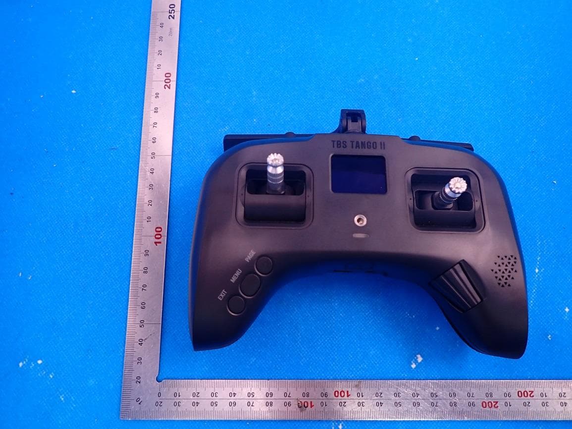
QOS-TANGO2
Aug 25, 2021Remote Control Radio
Equipment Class
DTS - Digital Transmission System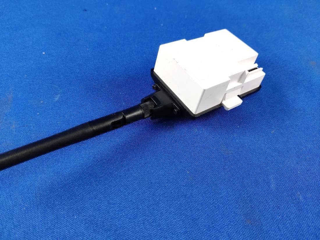
QOS-TCMICROTX
Apr 22, 2021MICRO TX
Equipment Class
DTS - Digital Transmission System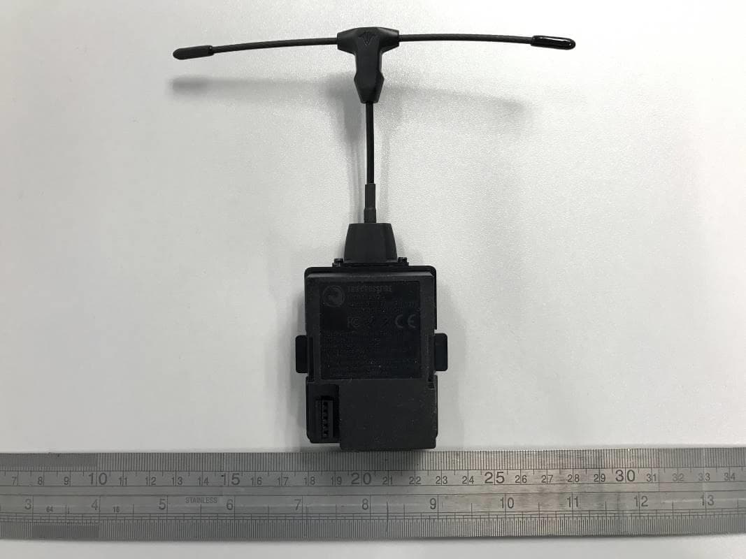
QOS-TXMICRO
Dec 18, 2020915MHz and 2.4GHz Wi-Fi Transmitter Module (Transceiver)
Equipment Class
DTS - Digital Transmission System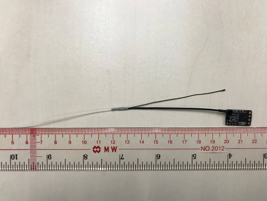
QOS-RXNANO
Feb 23, 2020915 MHz Receiver Module (Transceiver)
Equipment Class
DSS - Part 15 Spread Spectrum Transmitter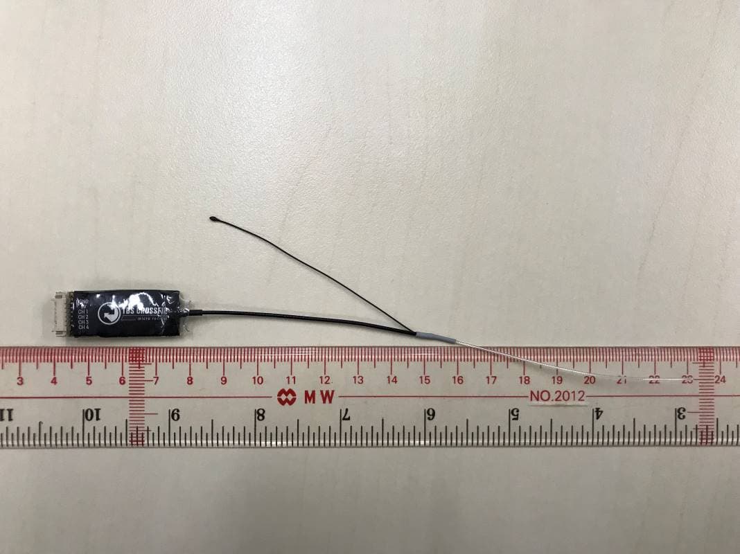
QOS-RXMICRO
Feb 23, 2020915 MHz Receiver Module (Transceiver)
Equipment Class
DSS - Part 15 Spread Spectrum Transmitter