QOS-TANGO2Remote Control Radio
TBS Avionics Limited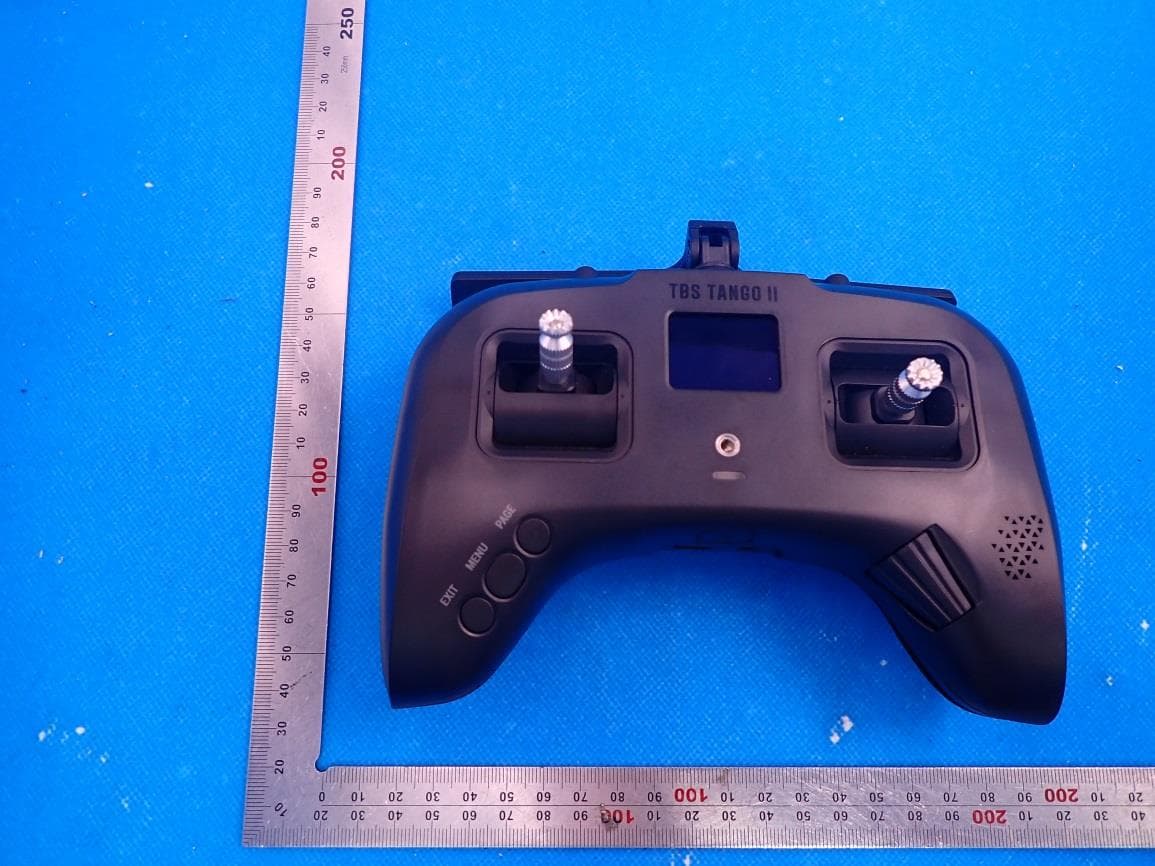
Click to zoom
Application Details
- Equipment Class
- DTS - Digital Transmission System
- Date of Grant
- Aug 25, 2021
- Application Purpose
- Original Equipment
- Date of Application
- Aug 25, 2021
- Equipment Note
- Remote Control Radio
- Frequency Range
- 2412.00000000 - 2462.00000000
- Company
- TBS Avionics Limited
- Country
- China
Documents & Files
Document Text
Text extracted from the exhibit documents filed with the FCC. Open a document above to read the original.
Users Manual
TBS TANGO 2 RadioRevision 2021-08-06 Compact all-in-one Remote Control Radio with TBS Crossfire System The TBS TANGO 2 remote control is an all-in-one system made for R/C enthusiasts. It features a built-in TBS Crossfire MicroTX radio module. Input controls are provided by full-size hall gimbals. A bright display shows the radio status and telemetry. Key features •Compact and ergonomic All-in-one (AIO) radio •Integrated TBS CROSSFIRE MicroTX - up to 500/250mW (rev3/ revision1+2) •Runs TBS FreedomTX, a temporary OpenTX fork •Industry’s lowest latency - only achievable with an AIO solution! •Travel and beginner friendly •Full-size digital hall gimbals •Unconventional low-profile switches for transportability, reliability and durability •Foldable antenna - also doubles as a kickstand •TBS CLOUD ready (future proof) •Digital trims (compatible with traditional R/C aircraft) •Solid build with quality components •Multi module capable (rev2 + 3) 1 Table of contents Attention Getting ready FAQ Note How-To videos Updating Overview Detailed overview Start with your radio Power up USB Joystick SD card content Configuration controls Changing stick mode Changing channel mixing and end-points Flying Wings Radio configuration menu Tools Crossfire Menu is missing Memory card Radio setup Global functions Hardware Version Calibration Model selection/ configuration menu General overview Model select Manage models Create models 2 OpenTX configuration menu OpenTX setup Flight modes Inputs Mixer Outputs Curves Logical switches Special functions Custom scripts Telemetry Display Usage Neck-strap Bind Model ID Set failsafe Set up switch warning Crossfire functions Status indicator Stick trim Battery protection Alert prompts Inside the radio Removing the battery Changing the flight stick mode Adjusting throttle ratchet strength Adjusting stick tension Adjusting stick range Upgrading / changing the gimbals Changing gimbal springs Additional informations 3 TBS CLOUD Menu Initiate the WiFi module Connection to a WiFi hotspot Firmware upgrade Backing-up the SD-card content Update FreedomTX Update the build in Crossfire Update the SD card content Update from FreedomTX 1.XX to 1.2X or later Firmware dependencies Programming examples LQ warning (audio) Self-holding switches (Switch E and F) Instant trim FAQ FCC statement RF Exposure Information: FCC ID of TBS Products 4 Specifications Type:All-in-one (AIO) integrated radio RC system:Built-in TBS CROSSFIRE MicroTX Output power:25mW to 1W Frequency Bands:868MHz (EU, Russia), 915MHz (USA, Asia, Australia) Antenna:Standard full-size TX antenna Switchable antenna polarization - horizontal / vertical Holding style:Pinch, thumb, and hybrid friendly Default stick mode:Mode 2, throttle and yaw left (user-changeable) Display:High-resolution 1.2” OLED-panel, 128 x 96 pixels Models:Standard and Pro model. PRO model has folding gimbals Battery:Lithium-polymer 3.7V 5000mAh internal battery pack, USB-C charging Runtime:Approx. 8 hours Channels:8- or 12-channels (CROSSFIRE) Operating range:Variable depending on output power and radio environment GimbalsFull-size hall sensor gimbals, Adjustable vertical range, Adjustable spring tension, Foldable sticks (PRO version only), m3 threading Controls: 2x Quad full-size hall gimbals 2x Two-position switches 2x Three-position switches 2x Lower-shoulder momentary buttons 3x Configuration buttons 1x Rocker switch 1x Power-on button Ports:3.5mm headphone audio-jack for OpenTX voice support USB-C for software updates and charging Neck-strap mounting:Screw on mount - sold separately Speaker:1W, for OpenTx voice support Simulator compatibility:Yes, over USB-C Working temperature:0 - 40 °C Size:W 157 x L130 x H70 mm (H50 mm folded) Weight:345 grams Kit contents:1x TBS TANGO 2 Radio Controller, 1x SD-card pre-setup 5 Attention These Long Range Systems are capable of radio frequency transmissions and output power that may be not allowed in your country. Please always check your local RF legislation and output power according to the regulation. A general rule for RC aircrafts is that they must be controlled always under sight of view, check your RC regulation to keep up to date with regulations. Getting ready Getting set up and ready to fly is a quick and simple task. In most cases plug&play when using TBS equipment. FAQ If you got any question after reading this manual you should visit theTBS FAQsection Note This manual is written based on FreedomTX 1.26,Crossfire 4.11 and WiFi 1.41. If some functions are not available for you, please update your system to these or later versions. How-To videos A short playlist on how to backup and update the sd card, Crossfire and the Tango 2 fw, as well as how setup the switch warningscan be found here Updating In order to update and configure your Tango 2 and the in-build Crossfire, you need the TBS Agent X, which you can download from theTBS shop. To update your Crossfire, connect it by the USB-port of the transmitter and run the update by Agent X. For detailed instructions on how to use the Agent X, have a look at theAgent X manual. 6 Overview The following diagrams indicate the essential input controls (green) and features (red) of the radio. 7 Detailed overview Power button, status LED, neck-strap hook and OLED display Left gimbal and configuration menu buttons Radio control buttonsRocker switch, power button, ports and speaker Left two-position (A/L1) and three-position (B/L2) switch Right two-position (D/R1) switch and three-position (C/R2) switch 8 Start with your radio Getting set up and ready to fly is a quick and simple task. In most cases plug&play when using TBS equipment. Power up Press and hold the Power-button for three seconds until the animation completes. The TBS TANGO II screen will welcome you and the power button lights up yellow. USB Joystick Plug-in a USB-C cable and a menu will appear where you can activate USB joystick mode. This mode will work with the most common simulators available. SD card…
Text truncated - open the document above for the full version.
External Photos
External Photos OUTSIDE VIEW-1 OF EUT OUTSIDE VIEW-2 OF EUT OUTSIDE VIEW-3 OF EUT OUTSIDE VIEW-4 OF EUT OUTSIDE VIEW-5 OF EUT OUTSIDE VIEW-6 OF EUT PORT VIEW OF EUT
ID Label/Location Info
FCC ID Label Location
Test Report
Page 1 of 80 Report No.: AGC11447210601FE05 FCC ID : QOS-TANGO2 APPLICATION PURPOSE : Original Equipment PRODUCT DESIGNATION : TANGO 2 BRAND NAME : TBS MODEL NAME : TANGO 2 APPLICANT : TBS Avionics Limited DATE OF ISSUE : Jul. 09, 2021 STANDARD(S) TEST PROCEDURE(S) : FCC Part 15.247 REPORT VERSION : V1.0 Attestation of Global Compliance (Shenzhen) Co., Ltd FCC Test Report Report No.: AGC11447210601FE05 Page 2 of 80 REPORT REVISE RECORD Report Version Revise Time Issued Date Valid Version Notes V1.0 / Jul. 09, 2021 Valid Initial Release Report No.: AGC11447210601FE05 Page 3 of 80 TABLE OF CONTENTS 1. VERIFICATION OF CONFORMITY .................................................................................................................. 5 2. GENERAL INFORMATION .............................................................................................................................. 6 2.1. PRODUCT DESCRIPTION ........................................................................................................................ 6 2.2. TABLE OF CARRIER FREQUENCYS ....................................................................................................... 6 2.3. IEEE 802.11N MODULATION SCHEME .................................................................................................... 7 2.4. RELATED SUBMITTAL(S) / GRANT (S) .................................................................................................... 7 2.5. TEST METHODOLOGY ............................................................................................................................. 7 2.6. SPECIAL ACCESSORIES ......................................................................................................................... 7 2.7. EQUIPMENT MODIFICATIONS ................................................................................................................. 7 2.8. ANTENNA REQUIREMENT....................................................................................................................... 8 3. MEASUREMENT UNCERTAINTY ................................................................................................................... 9 4. DESCRIPTION OF TEST MODES ................................................................................................................. 10 5. SYSTEM TEST CONFIGURATION ................................................................................................................ 11 5.1. CONFIGURATION OF EUT SYSTEM ...................................................................................................... 11 5.2. EQUIPMENT USED IN EUT SYSTEM ..................................................................................................... 11 5.3. SUMMARY OF TEST RESULTS .............................................................................................................. 11 6. TEST FACILITY .............................................................................................................................................. 12 7. OUTPUT POWER ........................................................................................................................................... 13 7.1. MEASUREMENT PROCEDURE ............................................................................................................. 13 7.2. TEST SET-UP (BLOCK DIAGRAM OF CONFIGURATION) .................................................................... 13 7.3. LIMITS AND MEASUREMENT RESULT .................................................................................................. 14 8. BANDWIDTH .................................................................................................................................................. 15 8.1. MEASUREMENT PROCEDURE ............................................................................................................. 15 8.2. TEST SET-UP (BLOCK DIAGRAM OF CONFIGURATION) .................................................................... 15 8.3. LIMITS AND MEASUREMENT RESULTS ............................................................................................... 16 9. CONDUCTED SPURIOUS EMISSION........................................................................................................... 27 9.1. MEASUREMENT PROCEDURE ............................................................................................................. 27 9.2. TEST SET-UP (BLOCK DIAGRAM OF CONFIGURATION) .................................................................... 27 9.3. MEASUREMENT EQUIPMENT USEDJN ................................................................................................ 27 9.4. LIMITS AND MEASUREMENT RESULT .................................................................................................. 27 Report No.: AGC11447210601FE05 Page 4 of 80 10. MAXIMUM CONDUCTED OUTPUT POWER SPECTRAL DENSITY ........................................................ 39 10.1 MEASUREMENT PROCEDURE ............................................................................................................ 39 10.2 TEST SET-UP (BLOCK DIAGRAM OF CONFIGURATION) ................................................................... 39 10.3 MEASUREMENT EQUIPMENT USED ................................................................................................... 39 10.4 LIMITS AND MEASUREMENT RESULT ................................................................................................. 39 11. RADIATED EMISSION ................................................................................................................................. 45 11.1. MEASUREMENT PROCEDURE............................................................................................................ 45 11.2. TEST SETUP ..................................................................................................................................…
Text truncated - open the document above for the full version.
Test Report
Report No.: AGC11447210601FE05 Page 49 of 80 EUT TANGO 2 Model Name TANGO 2 Temperature 25°C Relative Humidity 60% Pressure 960hPa Test Voltage Normal Voltage Test Mode 802.11b with date rate 1 2412MHz Antenna Vertical NO. Freq. [MHz] Level [dBμV/m] Factor [dB] Limit [dBμV/m] Margin [dB] Height [cm] Angle [°] Polarity 1 40.6700 29.98 11.91 40.00 10.02 100 108 Vertical 2 52.3100 31.69 11.49 40.00 8.31 100 330 Vertical 3 99.8400 26.36 11.30 43.50 17.14 100 349 Vertical 4 125.0600 30.55 13.81 43.50 12.95 100 145 Vertical 5 191.9900 32.10 12.43 43.50 11.40 100 177 Vertical 6 335.5500 28.19 17.32 46.00 17.81 100 15 Vertical RESULT: PASS Note: 1. Factor=Antenna Factor + Cable loss, Margin=Limit-Level. 2. The “Factor” value can be calculated automatically by software of measurement system. 3. All test modes had been pre-tested. The 802.11b at low channel is the worst case and recorded in the report. Report No.: AGC11447210601FE05 Page 50 of 80 Radiated emission above 1GHz EUT TANGO 2 Model Name TANGO 2 Temperature 25°C Relative Humidity 60% Pressure 960hPa Test Voltage Normal Voltage Test Mode 802.11b with date rate 1 2412MHz Antenna Horizontal FrequencyMeter ReadingFactorEmission LevelLimitsMargin (MHz)(dBμV)(dB)(dBμV/m)(dBμV/m)(dB) 4824.00054.630.0854.7174-19.29 peak 4824.00045.180.0845.2654-8.74 AVG 7236.00049.322.2151.5374-22.47 peak 7236.00040.262.2142.4754-11.53 AVG Remark: Factor = Antenna Factor + Cable Loss – Pre-amplifier. Value Type EUT TANGO 2 Model Name TANGO 2 Temperature 25°C Relative Humidity 60% Pressure 960hPa Test Voltage Normal Voltage Test Mode 802.11b with date rate 1 2412MHz Antenna Vertical FrequencyMeter ReadingFactorEmission LevelLimitsMargin (MHz)(dBμV)(dB)(dBμV/m)(dBμV/m)(dB) 4824.00055.280.0855.3674-18.64 peak 4824.00045.360.0845.4454-8.56 AVG 7236.00051.072.2153.2874-20.72 peak 7236.00040.822.2143.0354-10.97 AVG Remark: Factor = Antenna Factor + Cable Loss – Pre-amplifier. Value Type Report No.: AGC11447210601FE05 Page 51 of 80 EUT TANGO 2 Model Name TANGO 2 Temperature 25°C Relative Humidity 60% Pressure 960hPa Test Voltage Normal Voltage Test Mode 802.11b with date rate 1 2437MHz Antenna Horizontal FrequencyMeter ReadingFactorEmission LevelLimitsMargin (MHz)(dBμV)(dB)(dBμV/m)(dBμV/m)(dB) 4874.00056.390.1456.5374-17.47 peak 4874.00045.980.1446.1254-7.88 AVG 7311.00051.022.3653.3874-20.62 peak 7311.00040.262.3642.6254-11.38 AVG Remark: Factor = Antenna Factor + Cable Loss – Pre-amplifier. Value Type EUT TANGO 2 Model Name TANGO 2 Temperature 25°C Relative Humidity 60% Pressure 960hPa Test Voltage Normal Voltage Test Mode 802.11b with date rate 1 2437MHz Antenna Vertical FrequencyMeter ReadingFactorEmission LevelLimitsMargin (MHz)(dBμV)(dB)(dBμV/m)(dBμV/m)(dB) 4874.00055.320.1455.4674-18.54 peak 4874.00046.210.1446.3554-7.65 AVG 7311.00050.232.3652.5974-21.41 peak 7311.00040.372.3642.7354-11.27 AVG Remark: Factor = Antenna Factor + Cable Loss – Pre-amplifier. Value Type Report No.: AGC11447210601FE05 Page 52 of 80 EUT TANGO 2 Model Name TANGO 2 Temperature 25°C Relative Humidity 60% Pressure 960hPa Test Voltage Normal Voltage Test Mode 802.11b with date rate 1 2462MHz Antenna Horizontal FrequencyMeter ReadingFactorEmission LevelLimitsMargin (MHz)(dBμV)(dB)(dBμV/m)(dBμV/m)(dB) 4924.00054.370.2254.5974-19.41 peak 4924.00043.240.2243.4654-10.54 AVG 7386.00049.282.6451.9274-22.08 peak 7386.00040.052.6442.6954-11.31 AVG Remark: Factor = Antenna Factor + Cable Loss – Pre-amplifier. Value Type EUT TANGO 2 Model Name TANGO 2 Temperature 25°C Relative Humidity 60% Pressure 960hPa Test Voltage Normal Voltage Test Mode 802.11b with date rate 1 2462MHz Antenna Vertical FrequencyMeter ReadingFactorEmission LevelLimitsMargin (MHz)(dBμV)(dB)(dBμV/m)(dBμV/m)(dB) 4924.00056.140.2256.3674-17.64 peak 4924.00045.130.2245.3554-8.65 AVG 7386.00051.092.6453.7374-20.27 peak 7386.00042.382.6445.0254-8.98 AVG Remark: Factor = Antenna Factor + Cable Loss – Pre-amplifier. Value Type RESULT: PASS Note: The amplitude of other spurious emissions from 1G to 25 GHz which are attenuated more than 20 dB below the permissible value need not be reported. Factor = Antenna Factor + Cable loss - Amplifier gain, Margin=Emission Level-Limit. The “Factor” value can be calculated automatically by software of measurement system. All test modes had been pre-tested. The 802.11b mode is the worst case and recorded in the report. Report No.: AGC11447210601FE05 Page 53 of 80 Test result for band edge emission at restricted bands EUT TANGO 2 Model Name TANGO 2 Temperature 25°C Relative Humidity 60% Pressure 960hPa Test Voltage Normal Voltage Test Mode 802.11b with data rate 1 2412MHz Antenna Horizontal Test Graph for Peak Measurement Test Graph for Average Measurement RESULT: PASS Report No.: AGC11447210601FE05 Page 54 of 80 EUT TANGO 2 Model Name TANGO 2 Temperature 25°C Relative Humidity 60% Pressure 960hPa Test Voltage Normal Voltage Test Mode 802.11b with data rate 1 2412MHz Antenna Vertical Test Graph for Peak Measurement Test Graph for Average Measurement RESULT: PASS Report No.: AGC11447210601FE05 Page 55 of 80 EUT TANGO 2 Model Name TANGO 2 Temperature 25°C Relative Humidity 60% Pressure 960hPa Test Voltage Normal Voltage Test Mode 802.11b with data rate 1 2462MHz Antenna Horizontal Test Graph for Peak Measurement Test Graph for Average Measurement RESULT: PASS Report No.: AGC11447210601FE05 Page 56 of 80 EUT TANGO 2 Model Name TANGO 2 Temperature 25°C Relative Humidity 60% Pressure 960hPa Test Voltage Normal Voltage Test Mode 802.11b with data rate 1 2462MHz Antenna Vertical Test Graph for Peak Measurement Test Graph for Average Measurement RESULT: PASS Report No.: AGC11447210601FE05 Page 57 of 80 EUT TANGO 2 Model Name TANGO 2 Temperature 25°C Relative Humidity 60% Pressure 960hPa Test Voltage Normal Voltage Test Mode 802.11g with data rate 6 2412MHz Antenna Horizontal Test Graph for Peak Measurement Test Graph for Average Measurement RESULT: PASS Report No.: AGC11447210601FE05 Page 58 of 80 EUT TANGO 2 Mo…
Text truncated - open the document above for the full version.
Test Report
Report No.: AGC11447210601FE05 Page 76 of 80 INTERNAL VIEW-3 OF EUT INTERNAL VIEW-4 OF EUT Report No.: AGC11447210601FE05 Page 77 of 80 INTERNAL VIEW-5 OF EUT INTERNAL VIEW-6 OF EUT Report No.: AGC11447210601FE05 Page 78 of 80 INTERNAL VIEW-7 OF EUT INTERNAL VIEW-8 OF EUT WIFI Antenna Report No.: AGC11447210601FE05 Page 79 of 80 INTERNAL VIEW-9 OF EUT INTERNAL VIEW-10 OF EUT Report No.: AGC11447210601FE05 Page 80 of 80 INTERNAL VIEW-11 OF EUT VIEW OF BATTERY ----END OF REPORT---- LORA Antenna Conditions of Issuance of Test Reports 1. All samples and goods are accepted by the Attestation of Global Compliance (Shenzhen) Co., Ltd (the “Company”) solely for testing and reporting in accordance with the following terms and conditions. The company provides its services on the basis that such terms and conditions constitute express agreement between the company and any person, firm or company requesting its services (the “Clients”). 2. Any report issued by Company as a result of this application for testing services (the “Report”) shall be issued in confidence to the Clients and the Report will be strictly treated as such by the Company. It may not be reproduced either in its entirety or in part and it may not be used for advertising or other unauthorized purposes without the written consent of the Company. The Clients to whom the Report is issued may, however, show or send it, or a certified copy thereof prepared by the Company to its customer, supplier or other persons directly concerned. The Company will not, without the consent of the Clients, enter into any discussion or correspondence with any third party concerning the contents of the Report, unless required by the relevant governmental authorities, laws or court orders. 3.The Company shall not be called or be liable to be called to give evidence or testimony on the Report in a court of law without its prior written consent, unless required by the relevant governmental authorities, laws or court orders. 4. The non-CMA report issued by AGC is only permitted to be used by the client as internal reference use and shall not be used for public demonstration purpose. 5. In the event of the improper use of the report as determined by the Company, the Company reserves the right to withdraw it, and to adopt any other additional remedies which may be appropriate. 6. Samples submitted for testing are accepted on the understanding that the Report issued cannot form the basis of, or be the instrument for, any legal action against the Company. 7. The Company will not be liable for or accept responsibility for any loss or damage however arising from the use of information contained in any of its Reports or in any communication whatsoever about its said tests or investigations. 8.Clients wishing to use the Report in court proceedings or arbitration shall inform the Company to that effect prior to submitting the sample for testing. 9. The Company is not responsible for recalling the electronic version of the original report when any revision is made to them. The Client assumes the responsibility to providing the revised version to any interested party who uses them. 10. Subject to the variable length of retention time for test data and report stored hereinto as otherwise specifically required by individual accreditation authorities, the Company will only keep the supporting test data and information of the test report for a period of six years. The data and information will be disposed of after the aforementioned retention period has elapsed. Under no circumstances shall we provide any data and information which has been disposed of after retention period. Under no circumstances shall we be liable for damage of any kind, including (but not limited to) compensatory damages, lost profits, lost data, or any form of special, incidental, indirect, consequential or punitive damages of any kind, whether based on breach of contract of warranty, tort (including negligence), product liability or otherwise, even if we are informed in advance of the possibility of such damages.
Test Report
Page 1 of 80 Report No.: AGC11447210601FE05 FCC ID : QOS-TANGO2 APPLICATION PURPOSE : Original Equipment PRODUCT DESIGNATION : TANGO 2 BRAND NAME : TBS MODEL NAME : TANGO 2 APPLICANT : TBS Avionics Limited DATE OF ISSUE : Jul. 09, 2021 STANDARD(S) TEST PROCEDURE(S) : FCC Part 15.247 REPORT VERSION : V1.0 Attestation of Global Compliance (Shenzhen) Co., Ltd FCC Test Report Report No.: AGC11447210601FE05 Page 2 of 80 REPORT REVISE RECORD Report Version Revise Time Issued Date Valid Version Notes V1.0 / Jul. 09, 2021 Valid Initial Release Report No.: AGC11447210601FE05 Page 3 of 80 TABLE OF CONTENTS 1. VERIFICATION OF CONFORMITY .................................................................................................................. 5 2. GENERAL INFORMATION .............................................................................................................................. 6 2.1. PRODUCT DESCRIPTION ........................................................................................................................ 6 2.2. TABLE OF CARRIER FREQUENCYS ....................................................................................................... 6 2.3. IEEE 802.11N MODULATION SCHEME .................................................................................................... 7 2.4. RELATED SUBMITTAL(S) / GRANT (S) .................................................................................................... 7 2.5. TEST METHODOLOGY ............................................................................................................................. 7 2.6. SPECIAL ACCESSORIES ......................................................................................................................... 7 2.7. EQUIPMENT MODIFICATIONS ................................................................................................................. 7 2.8. ANTENNA REQUIREMENT....................................................................................................................... 8 3. MEASUREMENT UNCERTAINTY ................................................................................................................... 9 4. DESCRIPTION OF TEST MODES ................................................................................................................. 10 5. SYSTEM TEST CONFIGURATION ................................................................................................................ 11 5.1. CONFIGURATION OF EUT SYSTEM ...................................................................................................... 11 5.2. EQUIPMENT USED IN EUT SYSTEM ..................................................................................................... 11 5.3. SUMMARY OF TEST RESULTS .............................................................................................................. 11 6. TEST FACILITY .............................................................................................................................................. 12 7. OUTPUT POWER ........................................................................................................................................... 13 7.1. MEASUREMENT PROCEDURE ............................................................................................................. 13 7.2. TEST SET-UP (BLOCK DIAGRAM OF CONFIGURATION) .................................................................... 13 7.3. LIMITS AND MEASUREMENT RESULT .................................................................................................. 14 8. BANDWIDTH .................................................................................................................................................. 15 8.1. MEASUREMENT PROCEDURE ............................................................................................................. 15 8.2. TEST SET-UP (BLOCK DIAGRAM OF CONFIGURATION) .................................................................... 15 8.3. LIMITS AND MEASUREMENT RESULTS ............................................................................................... 16 9. CONDUCTED SPURIOUS EMISSION........................................................................................................... 27 9.1. MEASUREMENT PROCEDURE ............................................................................................................. 27 9.2. TEST SET-UP (BLOCK DIAGRAM OF CONFIGURATION) .................................................................... 27 9.3. MEASUREMENT EQUIPMENT USEDJN ................................................................................................ 27 9.4. LIMITS AND MEASUREMENT RESULT .................................................................................................. 27 Report No.: AGC11447210601FE05 Page 4 of 80 10. MAXIMUM CONDUCTED OUTPUT POWER SPECTRAL DENSITY ........................................................ 39 10.1 MEASUREMENT PROCEDURE ............................................................................................................ 39 10.2 TEST SET-UP (BLOCK DIAGRAM OF CONFIGURATION) ................................................................... 39 10.3 MEASUREMENT EQUIPMENT USED ................................................................................................... 39 10.4 LIMITS AND MEASUREMENT RESULT ................................................................................................. 39 11. RADIATED EMISSION ................................................................................................................................. 45 11.1. MEASUREMENT PROCEDURE............................................................................................................ 45 11.2. TEST SETUP ..................................................................................................................................…
Text truncated - open the document above for the full version.
Test Report
Report No.: AGC11447210601FE05 Page 76 of 80 INTERNAL VIEW-3 OF EUT INTERNAL VIEW-4 OF EUT Report No.: AGC11447210601FE05 Page 77 of 80 INTERNAL VIEW-5 OF EUT INTERNAL VIEW-6 OF EUT Report No.: AGC11447210601FE05 Page 78 of 80 INTERNAL VIEW-7 OF EUT INTERNAL VIEW-8 OF EUT WIFI Antenna Report No.: AGC11447210601FE05 Page 79 of 80 INTERNAL VIEW-9 OF EUT INTERNAL VIEW-10 OF EUT Report No.: AGC11447210601FE05 Page 80 of 80 INTERNAL VIEW-11 OF EUT VIEW OF BATTERY ----END OF REPORT---- LORA Antenna Conditions of Issuance of Test Reports 1. All samples and goods are accepted by the Attestation of Global Compliance (Shenzhen) Co., Ltd (the “Company”) solely for testing and reporting in accordance with the following terms and conditions. The company provides its services on the basis that such terms and conditions constitute express agreement between the company and any person, firm or company requesting its services (the “Clients”). 2. Any report issued by Company as a result of this application for testing services (the “Report”) shall be issued in confidence to the Clients and the Report will be strictly treated as such by the Company. It may not be reproduced either in its entirety or in part and it may not be used for advertising or other unauthorized purposes without the written consent of the Company. The Clients to whom the Report is issued may, however, show or send it, or a certified copy thereof prepared by the Company to its customer, supplier or other persons directly concerned. The Company will not, without the consent of the Clients, enter into any discussion or correspondence with any third party concerning the contents of the Report, unless required by the relevant governmental authorities, laws or court …
Text truncated - open the document above for the full version.
Contact Information
Applicant
Raphael Pirker(Manager)
Test Firm
Attestation of Global Compliance (Shenzhen) Co., LDoris Li
[email protected]+86-755-25234088
Technical Specifications
| # | Rule Parts | Frequency Range | Power Output |
|---|---|---|---|
| 1 | 15C | 2.41 GHz - 2.46 GHz | 21.70 mW |
Other Applications from TBS Avionics Limited
QOS-TCMICROTX
Apr 22, 2021MICRO TX
Equipment Class
DTS - Digital Transmission System
QOS-TXMICRO
Dec 18, 2020915MHz and 2.4GHz Wi-Fi Transmitter Module (Transceiver)
Equipment Class
DTS - Digital Transmission System
QOS-RXNANODIV
May 12, 2020915 MHz Receiver Module (Transceiver)
Equipment Class
DSS - Part 15 Spread Spectrum Transmitter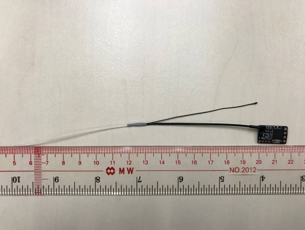
QOS-RXNANO
Feb 23, 2020915 MHz Receiver Module (Transceiver)
Equipment Class
DSS - Part 15 Spread Spectrum Transmitter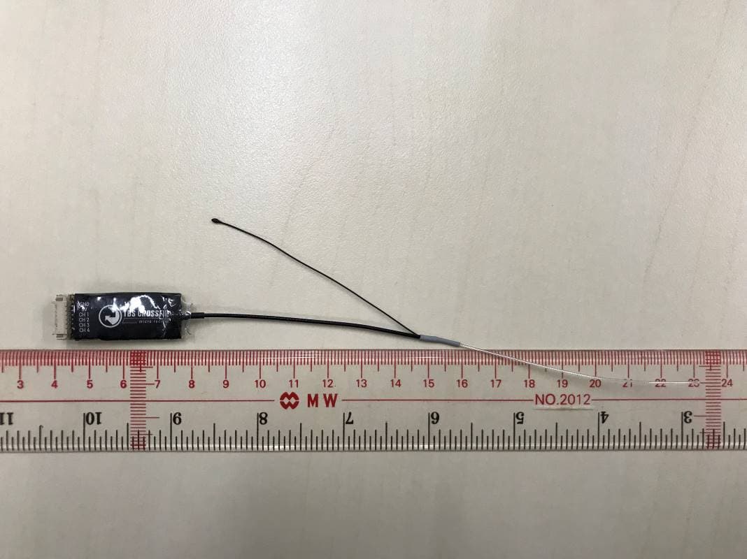
QOS-RXMICRO
Feb 23, 2020915 MHz Receiver Module (Transceiver)
Equipment Class
DSS - Part 15 Spread Spectrum Transmitter