QOS-TCMICROTXMICRO TX
TBS Avionics Limited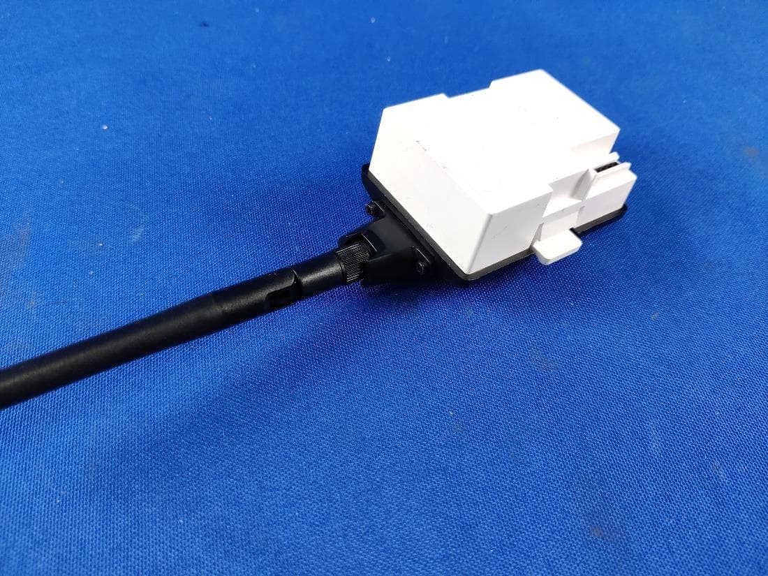
Click to zoom
Application Details
- Equipment Class
- DTS - Digital Transmission System
- Date of Grant
- Apr 22, 2021
- Application Purpose
- Original Equipment
- Date of Application
- Apr 22, 2021
- Equipment Note
- MICRO TX
- Frequency Range
- 2403.40000000 - 2469.80000000
- Company
- TBS Avionics Limited
- Country
- China
Documents & Files
Document Text
Text extracted from the exhibit documents filed with the FCC. Open a document above to read the original.
Users Manual
TBS TRACER 2.4GHz R/C SystemRevision 2021-02-03 High speed drone control system based on TBS Crossfire engine The TBS TRACER (XF) system is a R/C link system made for FPV enthusiasts. It features unheard of latency and performance without any of the clutter of choosing RF modes, link profiles. It just works. Two-way communications includes telemetry functionality and support for 3rd party autopilots. Key features •Low latency, high bandwidth, great range •Constant 250Hz uplink & downlink rate for super low latency •Immune to on-board noise •Two-way communication link with real-time link vitals and telemetry •Self-healing frequency hopping link •Super easy binding and configuration via OpenTX LUA, Agent X or TBS TANGO remote •Free output mappable outputs & antenna diversity •No issues when flying with multiple friends at the same time •Dynamic or selectable RF power (local restrictions apply) •Transmitter LED shows link health 1 Table of content Attention Getting ready FAQ Note Updating Hardware overview Micro transmitter module (MICRO TX): Nano transmitter module (NANO TX): Nano receiver (NANO RX): Nano receiver pwm version (NANO PWM): Why two antennas on the receivers? Radio connection JR-bay radios (TBS Tango) Adapter boards General functions Binding General note on model match When do i need to bind again Binding issue - Double green flashing Binding issue - OpenTx 2.3.10 Transmitter Receiver Receiver Update (OTA) Auto Bind & OTA Multi bind How to set it up Failsafe setup General setup Cut Failsafe position Transmission power 2 Transmitter LED status indicator Receiver LED status indicator MyVTX RC over MAVLink Receiver functions Output map CRSF Serial SBUS N.i. SBUS MAVLink PWM (Ch X) PPM DSMX LQ RSSI RSSI/LQ Smart Audio Channel number Available sensors with OpenTX Missing sensors In-built Voltage monitoring BST connection Additional information TBS CLOUD Menu Initiate the WiFi module Connection to a WiFi hotspot OTA update of the WiFi Module OpenTX setup for TRACER LQ warning in OpenTX Model-match in OpenTX VTx connection by CRSF 3 Vtx connection by SmartAudio Smart Audio or CRSF for the VTx? VTx button is not working Connection to an FC General wiring CRSF with BetaFlight and similar firmwares CRSF with KISS/ FETTEC BST to Eagletree Vector Mavlink with MAV FC’s Wireless configuration with ArduPilot/ PX4 by WiFi Wireless telemetry WiFi telemetry with BetaFlight/ INav Signal strength in Betaflight - BF < 4.1 and DJI OSD Signal strength in Betaflight - BF 4.1 and later CLI commands Signal strength in INav Link States LQ - Link quality RSSI - Relative signal strength indicator SNR - Signal-to-Noise ratio Warning levels What should i use in my OSD or radio Racing environment Factory reset Emergency Update FCC statement Additional FCC statement for TBS TRACER MICRO TX: FCC ID of TBS TRACER Products 4 Specifications Type:Two-Way Remote Control System Band:2.4GHz band RF powerFCC: 25mw - 1000mW selectable Modulation:GFSK Antenna:TX: 1x omnidirectional dipole antenna RX: 2x flexible t-style antenna R/C Channels: up to 12-channel digital stream outputs, standard 2.54mm servo connectors Radio compatibility:Any radio with JR-style bay or Mini-module bay. OpenTX recommended Interface:TX: RGB LED light, push button, configuration via CSRF (TBS TANGO, OpenTX ect. ), WiFi Failsafe:Pre-set servo positions or stops outputting servo pulse - selectable in configuration menu or via push button Operating range:15mi+/25km+ Input power:MICRO TX: +6 to 13V NANO TX: +5 to 9V NANO RX: +4.5V to 8.4V (down to 3.3V possible, but not recommended) All reverse-polarity protected, compatible for 2s Lipo direct Power consumption:TX: 1.1W, at 25mW Rx: 1W at 5V Ports:NANO RX: 2x Pin-headers for 1x BST and 2x CSRF or 4x Servo NANO PWM version: 6x Servo connector Working temperature:0 - 40°C Size:MICRO TX: 73 x 56 x 35 mm NANO RX: 11 x 8 Weight:Tx: 38g Rx: 3.2 grams incl. antennas 5 Attention Please always check your local RF legislation to set the output power according to the regulation. A general rule for RC aircrafts is that they must be controlled always under sight of view, check your RC regulation to keep up to date with regulations. Getting ready Getting set up and ready to fly is a quick and simple task. In most cases plug&play when using TBS equipment. To bind, place your TRACER MICRO TX or NANO TX into bind mode by pushing the button on the back of the device, then connect power to your receiver. It will enter bind mode automatically the first time. If you see a blue LED, please push the button once to confirm the start of the OTA firmware update and wait about 1 minute. When bind is complete, the LED on the back of the TRACER transmitter will indicate green. FAQ If you got any question after reading this manual you should visit the TBS FAQ section Note This manual is written based on TRACER FW 4.35. There may be minor variations depending on the version that is available at this moment. Updating In order to update and configure your TRACER, you need the TBS Agent X, which you can download from the TBS shop. To update your TRACER, connect it by USB and run the update by Agent X. The receiver will automatically get the update on the next bind (more information in the receiver update section) For detailed instructions on how to use the Agent X, have a look at the Agent X manual. 6 Hardware overview The following diagram indicates the essential inputs and features of the transmitters and receivers. Micro transmitter module (MICRO TX): Nano transmitter module (NANO TX): The NANO transmitter includes the same internals and functions as the MICRO TX. It is designed to fit into the mini-modul bay of newer FrSky radios, Tango 2 modul bay and any other radio with the mini-modul bay. 7 Nano receiver (NANO RX): Nano receiver pwm version (NANO PWM): This Rx is the same as the NANO RX but with 6 servo connectors installed. This Saves you the need for the PWM adapter board. Why two antennas on the receivers? The TRACER rec…
Text truncated - open the document above for the full version.
Cover Letter(s)
TBS Avionics Limited 9/F, Tungtex Building 203 Wai Yip Street, Kwun Tong, Hong Kong, China Office of Engineering Technology Federal Communications Commission 7435 Oakland Mills Road Columbia, MD 21046 USA Date: Mar. 17, 2021 Subject: Declaration Operating Channel Limitation FCC ID: QOS-TCMICROTX To Whom it may concern, This device is acting as slave/client device under the control of a master. The operating channels in 802.11 b/g/n mode for this device marketed to the US are firmware limited to channel 1 ~ 11 (2412 ~ 2462 MHz). The end-user has no possibility to select any other operating channels. If you have any questions, please feel free to contact me. Thank you. Sincerely, Signatory TBS Avionics Limited Contact person: Raphael Pirker Title: Manager
External Photos
External Photos OVERALL VIEW OF EUT-1 OVERALL VIEW OF EUT-2 OVERALL VIEW OF EUT-3 OVERALL VIEW OF EUT-4 LAB VIEW OF EUT
Internal Photos
Internal Photos OPEN VIEW OF EUT-1 OPEN VIEW OF EUT-2 OPEN VIEW OF EUT-3 OPEN VIEW OF EUT-4 2.4G Antenna INTERNAL VIEW-1 OF EUT INTERNAL VIEW-2 OF EUT 2.4G Antenna port INTERNAL VIEW-3 OF EUT INTERNAL VIEW-4 OF EUT WIFI Antenna INTERNAL VIEW-5 OF EUT
RF Exposure Info
CALIBRATION DATA PROBE CALIBRATION DATA DIPOLE CALIBRATION DATA
RF Exposure Info
Page 1 of 53 SAR Test Report Report No.: AGC11447201002FH01 FCC ID : QOS-TCMICROTX APPLICATION PURPOSE : Original Equipment PRODUCT DESIGNATION : MICRO TX BRAND NAME : TBS TRACER MODEL NAME : MICRO TX APPLICANT : TBS Avionics Limited DATE OF ISSUE : Jan. 29,2021 STANDARD(S) : IEEE Std. 1528:2013 FCC 47 CFR Part 2§2.1093:2013 IEEE Std C95.1 ™-2005 IEC 62209-1: 2016 REPORT VERSION : V1.0 Attestation of Global Compliance(Shenzhen) Co., Ltd. Report No.: AGC11447201002FH01 Page 2 of 53 Report Revise Record Report Version Revise Time Issued Date Valid Version Notes V1.0 / Jan. 29,2021 Valid Initial Release Report No.: AGC11447201002FH01 Page 3 of 53 Test Report Certification Applicant Name TBS Avionics Limited Applicant Address 9/F, Tungtex Building 203 Wai Yip Street, Kwun Tong, Hong Kong, China Manufacturer Name TBS Avionics Limited Manufacturer Address 9/F, Tungtex Building 203 Wai Yip Street, Kwun Tong, Hong Kong, China Factory Name TBS Avionics Limited Factory Address 9/F, Tungtex Building 203 Wai Yip Street, Kwun Tong, Hong Kong, China Product Designation MICRO TX Brand Name TBS TRACER Model Name MICRO TX Power Supply Rating: DC 3.5V to 13V, 2W Max. Applicable Standard IEEE Std. 1528:2013 FCC 47 CFR Part 2§2.1093:2013 IEEE Std C95.1 ™-2005 IEC 62209-1: 2016 Test Date Dec. 03,2020 to Jan. 28,2021 Report Template AGCRT-US-2.4G/SAR (2018-01-01) Note: The results of testing in this report apply to the product/system which was tested only. Prepared By Thea Huang (Project Engineer) Jan. 28,2021 Reviewed By Angela Li (Reviewer) Jan. 29,2021 Approved By Forrest Lei (Authorized Officer) Jan. 29,2021 Report No.: AGC11447201002FH01 Page 4 of 53 TABLE OF CONTENTS 1. SUMMARY OF MAXIMUM SAR VALUE ......................................................................................................... 5 2. GENERAL INFORMATION ............................................................................................................................... 6 2.1. EUT DESCRIPTION......................................................................................................................................... 6 3. SAR MEASUREMENT SYSTEM ........................................................................................................................ 7 3.1. THE SATIMO SYSTEM USED FOR PERFORMING COMPLIANCE TESTS CONSISTS OF FOLLOWING ITEMS .................. 7 3.2. COMOSAR E-FIELD PROBE .......................................................................................................................... 8 3.3. ROBOT .......................................................................................................................................................... 8 3.4. VIDEO POSITIONING SYSTEM .......................................................................................................................... 9 3.5. DEVICE HOLDER ............................................................................................................................................ 9 3.6. SAM TWIN PHANTOM ................................................................................................................................... 10 4. SAR MEASUREMENT PROCEDURE .............................................................................................................. 11 4.1. SPECIFIC ABSORPTION RATE (SAR) .............................................................................................................. 11 4.2. SAR MEASUREMENT PROCEDURE ................................................................................................................ 12 4.3. RF EXPOSURE CONDITIONS ......................................................................................................................... 14 5. TISSUE SIMULATING LIQUID ......................................................................................................................... 15 5.1. THE COMPOSITION OF THE TISSUE SIMULATING LIQUID..................................................................................... 15 5.2. TISSUE DIELECTRIC PARAMETERS FOR HEAD AND BODY PHANTOMS ............................................................... 15 5.3. TISSUE CALIBRATION RESULT ....................................................................................................................... 16 6. SAR SYSTEM CHECK PROCEDURE ........................................................................................................... 17 6.1. SAR SYSTEM CHECK PROCEDURES ............................................................................................................. 17 6.2. SAR SYSTEM CHECK ................................................................................................................................... 18 7. EUT TEST POSITION ..................................................................................................................................... 19 7.1. TEST POSITION ............................................................................................................................................ 19 8. SAR EXPOSURE LIMITS ............................................................................................................................... 20 9. TEST FACILITY .............................................................................................................................................. 21 10. TEST EQUIPMENT LIST .............................................................................................................................. 22 11. MEASUREMENT UNCERTAINTY ................................................................................................................ 23 12. CONDUCTED POWER MEASUREMENT ..................................................................................................... 26 13. TEST RESULTS ................................................................................................................…
Text truncated - open the document above for the full version.
Test Report
Page 1 of 56 FCC Test Report Report No.: AGC11447201002FE03 FCC ID : QOS-TCMICROTX APPLICATION PURPOSE : Original Equipment PRODUCT DESIGNATION : MICRO TX BRAND NAME : TBS TRACER MODEL NAME : MICRO TX APPLICANT : TBS Avionics Limited DATE OF ISSUE : Mar. 16, 2021 STANDARD(S) : FCC Part 15.247 REPORT VERSION : V1.0 Attestation of Global Compliance (Shenzhen) Co., Ltd Report No.: AGC11447201002FE03 Page 2 of 56 REPORT REVISE RECORD Report Version Revise Time Issued Date Valid Version Notes V1.0 / Mar. 16, 2021 Valid Initial Release Report No.: AGC11447201002FE03 Page 3 of 56 TABLE OF CONTENTS 1. VERIFICATION OF CONFORMITY .................................................................................................................. 5 2. GENERAL INFORMATION .............................................................................................................................. 6 2.1. PRODUCT DESCRIPTION ........................................................................................................................ 6 2.2. TABLE OF CARRIER FREQUENCYS ....................................................................................................... 6 2.3. RECEIVER INPUT BANDWIDTH .............................................................................................................. 7 2.4. EXAMPLE OF A HOPPING SEQUENCY IN DATA MODE ......................................................................... 7 2.5. EQUALLY AVERAGE USE OF FREQUENCIES AND BEHAVIOUR ......................................................... 7 2.6. RELATED SUBMITTAL(S) / GRANT (S) .................................................................................................... 8 2.7. TEST METHODOLOGY ............................................................................................................................. 8 2.8. SPECIAL ACCESSORIES ......................................................................................................................... 8 2.9. EQUIPMENT MODIFICATIONS ................................................................................................................. 8 2.10. ANTENNA REQUIREMENT..................................................................................................................... 8 3. MEASUREMENT UNCERTAINTY ................................................................................................................... 9 4. DESCRIPTION OF TEST MODES ................................................................................................................. 10 5. SYSTEM TEST CONFIGURATION ................................................................................................................ 11 5.1. CONFIGURATION OF EUT SYSTEM ...................................................................................................... 11 5.2. EQUIPMENT USED IN TESTED SYSTEM .............................................................................................. 11 5.3. SUMMARY OF TEST RESULTS .............................................................................................................. 11 6. TEST FACILITY .............................................................................................................................................. 12 7. PEAK OUTPUT POWER ................................................................................................................................ 13 7.1. MEASUREMENT PROCEDURE ............................................................................................................. 13 7.2. TEST SET-UP (BLOCK DIAGRAM OF CONFIGURATION) .................................................................... 13 7.3. LIMITS AND MEASUREMENT RESULT .................................................................................................. 14 8. 20DB BANDWIDTH ........................................................................................................................................ 16 8.1. MEASUREMENT PROCEDURE ............................................................................................................. 16 8.2. TEST SET-UP (BLOCK DIAGRAM OF CONFIGURATION) .................................................................... 16 8.3. LIMITS AND MEASUREMENT RESULTS ............................................................................................... 17 9. CONDUCTED SPURIOUS EMISSION........................................................................................................... 19 9.1. MEASUREMENT PROCEDURE ............................................................................................................. 19 Report No.: AGC11447201002FE03 Page 4 of 56 9.2. TEST SET-UP (BLOCK DIAGRAM OF CONFIGURATION) .................................................................... 19 9.3. MEASUREMENT EQUIPMENT USED .................................................................................................... 19 9.4. LIMITS AND MEASUREMENT RESULT .................................................................................................. 19 10. RADIATED EMISSION ................................................................................................................................. 25 10.1. MEASUREMENT PROCEDURE ........................................................................................................... 25 10.2. TEST SETUP ......................................................................................................................................... 27 10.3. LIMITS AND MEASUREMENT RESULT ............................................................................................... 28 10.4. TEST RESULT........................................................................................................................................ 28 11. NUMBER OF HOPPING FREQUENCY ......................................................................................…
Text truncated - open the document above for the full version.
Test Report
Report No.: AGC11447201002FE03 Page 41 of 56 TEST PLOT OF MIDDLE CHANNEL Report No.: AGC11447201002FE03 Page 42 of 56 TEST PLOT OF HIGH CHANNEL Report No.: AGC11447201002FE03 Page 43 of 56 13. FREQUENCY SEPARATION 13.1. MEASUREMENT PROCEDURE The EUT shall have its hopping function enabled. Use the following spectrum analyzer settings: 1. Span: Wide enough to capture the peaks of two adjacent channels. 2. RBW: Start with the RBW set to approximately 30% of the channel spacing; adjust as necessary to best identify the center of each individual channel. 3. Video (or average) bandwidth (VBW) ≥ RBW. 4. Sweep: Auto. e) Detector function: Peak. f) Trace: Max hold. g) Allow the trace to stabilize. Use the marker-delta function to determine the separation between the peaks of the adjacent channels. 13.2. TEST SETUP (BLOCK DIAGRAM OF CONFIGURATION) Same as described in section 6.2 13.3. MEASUREMENT EQUIPMENT USED The same as described in section 6.3 13.4. LIMITS AND MEASUREMENT RESULT Antenna 1 TEST MODE CHANNEL SEPARATION LIMIT RESULT MHz Pass Hopping 0.8028 ≥20dB BW TEST PLOT FOR FREQUENCY SEPARATION Report No.: AGC11447201002FE03 Page 44 of 56 14. FCC LINE CONDUCTED EMISSION TEST 14.1. LIMITS OF LINE CONDUCTED EMISSION TEST Frequency Maximum RF Line Voltage Q.P.( dBuV) Average( dBuV) 150kHz~500kHz 66-56 56-46 500kHz~5MHz 56 46 5MHz~30MHz 60 50 Note: 1. The lower limit shall apply at the transition frequency. 2. The limit decreases linearly with the logarithm of the frequency in the range 0.15 MHz to 0.50 MHz. 14.2. BLOCK DIAGRAM OF LINE CONDUCTED EMISSION TEST EUT & Support Units Report No.: AGC11447201002FE03 Page 45 of 56 14.3. PRELIMINARY PROCEDURE OF LINE CONDUCTED EMISSION TEST 1. The equipment was set up as per the test configuration to simulate typical actual usage per the user’s manual. When the EUT is a tabletop system, a wooden table with a height of 0.8 meters is used and is placed on the ground plane as per ANSI C63.10 (see Test Facility for the dimensions of the ground plane used). When the EUT is a floor-standing equipment, it is placed on the ground plane which has a 3-12 mm non-conductive covering to insulate the EUT from the ground plane. 2. Support equipment, if needed, was placed as per ANSI C63.10. 3. All I/O cables were positioned to simulate typical actual usage as per ANSI C63.10. 4. All support equipments received AC120V/60Hz power from a LISN, if any. 5. The EUT received DC 5V power from Control board which received AC120V/60Hz power from a LISN. 6. The test program was started. Emissions were measured on each current carrying line of the EUT using a spectrum Analyzer / Receiver connected to the LISN powering the EUT. The LISN has two monitoring points: Line 1 (Hot Side) and Line 2 (Neutral Side). Two scans were taken: one with Line 1 connected to Analyzer / Receiver and Line 2 connected to a 50 ohm load; the second scan had Line 1 connected to a 50 ohm load and Line 2 connected to the Analyzer / Receiver. 7. Analyzer / Receiver scanned from 150 kHz to 30MHz for emissions in each of the test modes. 8. During the above scans, the emissions were maximized by cable manipulation. 9. The test mode(s) were scanned during the preliminary test. Then, the EUT configuration and cable configuration of the above highest emission level were recorded for reference of final testing. 14.4. FINAL PROCEDURE OF LINE CONDUCTED EMISSION TEST 1. EUT and support equipment was set up on the test bench as per step 2 of the preliminary test. 2. A scan was taken on both power lines, Line 1 and Line 2, recording at least the six highest emissions. Emission frequency and amplitude were recorded into a computer in which correction factors were used to calculate the emission level and compare reading to the applicable limit. If EUT emission level was less – 2dB to the A.V. limit in Peak mode, then the emission signal was re-checked using Q.P and Average detector. 3. The test data of the worst case condition(s) was reported on the Summary Data page. Report No.: AGC11447201002FE03 Page 46 of 56 14.5. TEST RESULT OF LINE CONDUCTED EMISSION TEST Line Conducted Emission Test Line 1-L Report No.: AGC11447201002FE03 Page 47 of 56 Line Conducted Emission Test Line 2-N RESULT: PASS Report No.: AGC11447201002FE03 Page 48 of 56 APPENDIX A: PHOTOGRAPHS OF TEST SETUP RADIATED EMISSION TEST SETUP BELOW 1GHz RADIATED EMISSION TEST SETUP ABOVE 1GHz Report No.: AGC11447201002FE03 Page 49 of 56 CONDUCTED EMISSION TEST SETUP CONDUCTED TEST SETUP Report No.: AGC11447201002FE03 Page 50 of 56 APPENDIX B: PHOTOGRAPHS OF EUT OVERALL VIEW OF EUT-1 OVERALL VIEW OF EUT-2 Report No.: AGC11447201002FE03 Page 51 of 56 OVERALL VIEW OF EUT-3 OVERALL VIEW OF EUT-4 Report No.: AGC11447201002FE03 Page 52 of 56 LAB VIEW OF EUT OPEN VIEW OF EUT-1 Report No.: AGC11447201002FE03 Page 53 of 56 OPEN VIEW OF EUT-2 OPEN VIEW OF EUT-3 Report No.: AGC11447201002FE03 Page 54 of 56 OPEN VIEW OF EUT-4 INTERNAL VIEW-1 OF EUT 2.4G Antenna port 2.4G Antenna Report No.: AGC11447201002FE03 Page 55 of 56 INTERNAL VIEW-2 OF EUT INTERNAL VIEW-3 OF EUT WIFI Antenna Report No.: AGC11447201002FE03 Page 56 of 56 INTERNAL VIEW-4 OF EUT INTERNAL VIEW-5 OF EUT ----END OF REPORT---- Conditions of Issuance of Test Reports 1. All samples and goods are accepted by the Attestation of Global Compliance (Shenzhen) Co., Ltd (the “Company”) solely for testing and reporting in accordance with the following terms and conditions. The company provides its services on the basis that such terms and conditions constitute express agreement between the company and any person, firm or company requesting its services (the “Clients”). 2. Any report issued by Company as a result of this application for testing services (the “Report”) shall be issued in confidence to the Clients and the Report will be strictly treated as such by the Company. It may not be reproduced either in its entirety or in part and it may not be used for advertising or other unauthorized purposes without the writ…
Text truncated - open the document above for the full version.
Test Report
Page 1 of 77 Report No.: AGC11447201002FE05 FCC ID : QOS-TCMICROTX APPLICATION PURPOSE : Original Equipment PRODUCT DESIGNATION : MICRO TX BRAND NAME : TBS TRACER MODEL NAME : MICRO TX APPLICANT : TBS Avionics Limited DATE OF ISSUE : Apr. 14, 2021 STANDARD(S) TEST PROCEDURE(S) : FCC Part 15.247 REPORT VERSION : V1.0 Attestation of Global Compliance (Shenzhen) Co., Ltd FCC Test Report Report No.: AGC11447201002FE05 Page 2 of 77 REPORT REVISE RECORD Report Version Revise Time Issued Date Valid Version Notes V1.0 / Apr. 14, 2021 Valid Initial Release Report No.: AGC11447201002FE05 Page 3 of 77 TABLE OF CONTENTS 1. VERIFICATION OF CONFORMITY .................................................................................................................. 5 2. GENERAL INFORMATION .............................................................................................................................. 6 2.1. PRODUCT DESCRIPTION ........................................................................................................................ 6 2.2. TABLE OF CARRIER FREQUENCYS ....................................................................................................... 6 2.3. IEEE 802.11N MODULATION SCHEME .................................................................................................... 7 2.4. RELATED SUBMITTAL(S) / GRANT (S) .................................................................................................... 7 2.5. TEST METHODOLOGY ............................................................................................................................. 7 2.6. SPECIAL ACCESSORIES ......................................................................................................................... 7 2.7. EQUIPMENT MODIFICATIONS ................................................................................................................. 7 2.8. ANTENNA REQUIREMENT....................................................................................................................... 8 3. MEASUREMENT UNCERTAINTY ................................................................................................................... 9 4. DESCRIPTION OF TEST MODES ................................................................................................................. 10 5. SYSTEM TEST CONFIGURATION ................................................................................................................ 11 5.1. CONFIGURATION OF EUT SYSTEM ...................................................................................................... 11 5.2. EQUIPMENT USED IN EUT SYSTEM ..................................................................................................... 11 5.3. SUMMARY OF TEST RESULTS .............................................................................................................. 11 6. TEST FACILITY .............................................................................................................................................. 12 7. OUTPUT POWER ........................................................................................................................................... 13 7.1. MEASUREMENT PROCEDURE ............................................................................................................. 13 7.2. TEST SET-UP (BLOCK DIAGRAM OF CONFIGURATION) .................................................................... 13 7.3. LIMITS AND MEASUREMENT RESULT .................................................................................................. 14 8. BANDWIDTH .................................................................................................................................................. 15 8.1. MEASUREMENT PROCEDURE ............................................................................................................. 15 8.2. TEST SET-UP (BLOCK DIAGRAM OF CONFIGURATION) .................................................................... 15 8.3. LIMITS AND MEASUREMENT RESULTS ............................................................................................... 16 9. CONDUCTED SPURIOUS EMISSION........................................................................................................... 27 9.1. MEASUREMENT PROCEDURE ............................................................................................................. 27 9.2. TEST SET-UP (BLOCK DIAGRAM OF CONFIGURATION) .................................................................... 27 9.3. MEASUREMENT EQUIPMENT USEDJN ................................................................................................ 27 9.4. LIMITS AND MEASUREMENT RESULT .......................…
Text truncated - open the document above for the full version.
Contact Information
Applicant
Raphael Pirker(Manager)
Test Firm
Attestation of Global Compliance (Shenzhen) Co., LDoris Li
[email protected]+86-755-25234088
Technical Specifications
| # | Rule Parts | Frequency Range | Power Output |
|---|---|---|---|
| 2 | 15C | 2.40 GHz - 2.47 GHz | 815.00 mW |
Other Applications from TBS Avionics Limited
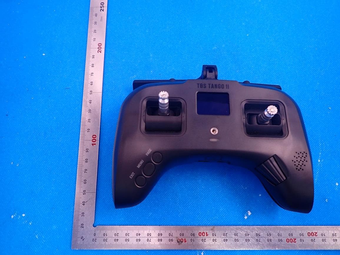
QOS-TANGO2
Aug 25, 2021Remote Control Radio
Equipment Class
DTS - Digital Transmission System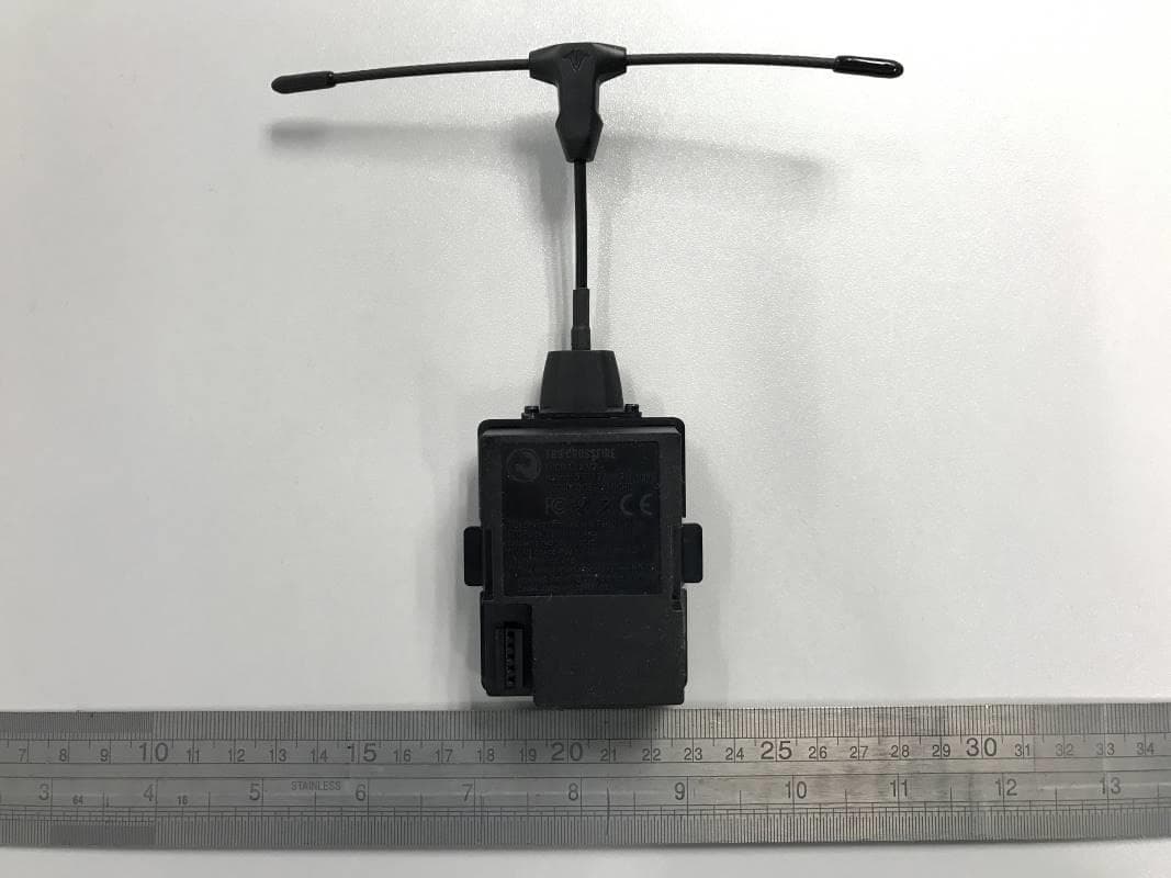
QOS-TXMICRO
Dec 18, 2020915MHz and 2.4GHz Wi-Fi Transmitter Module (Transceiver)
Equipment Class
DTS - Digital Transmission System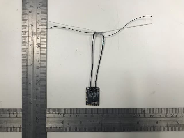
QOS-RXNANODIV
May 12, 2020915 MHz Receiver Module (Transceiver)
Equipment Class
DSS - Part 15 Spread Spectrum Transmitter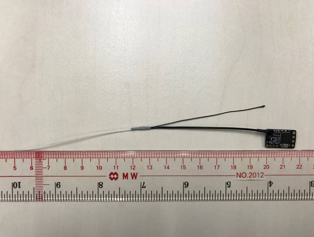
QOS-RXNANO
Feb 23, 2020915 MHz Receiver Module (Transceiver)
Equipment Class
DSS - Part 15 Spread Spectrum Transmitter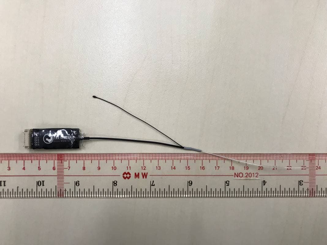
QOS-RXMICRO
Feb 23, 2020915 MHz Receiver Module (Transceiver)
Equipment Class
DSS - Part 15 Spread Spectrum Transmitter