QOS-TXMICRO915MHz and 2.4GHz Wi-Fi Transmitter Module (Transceiver)
TBS Avionics Limited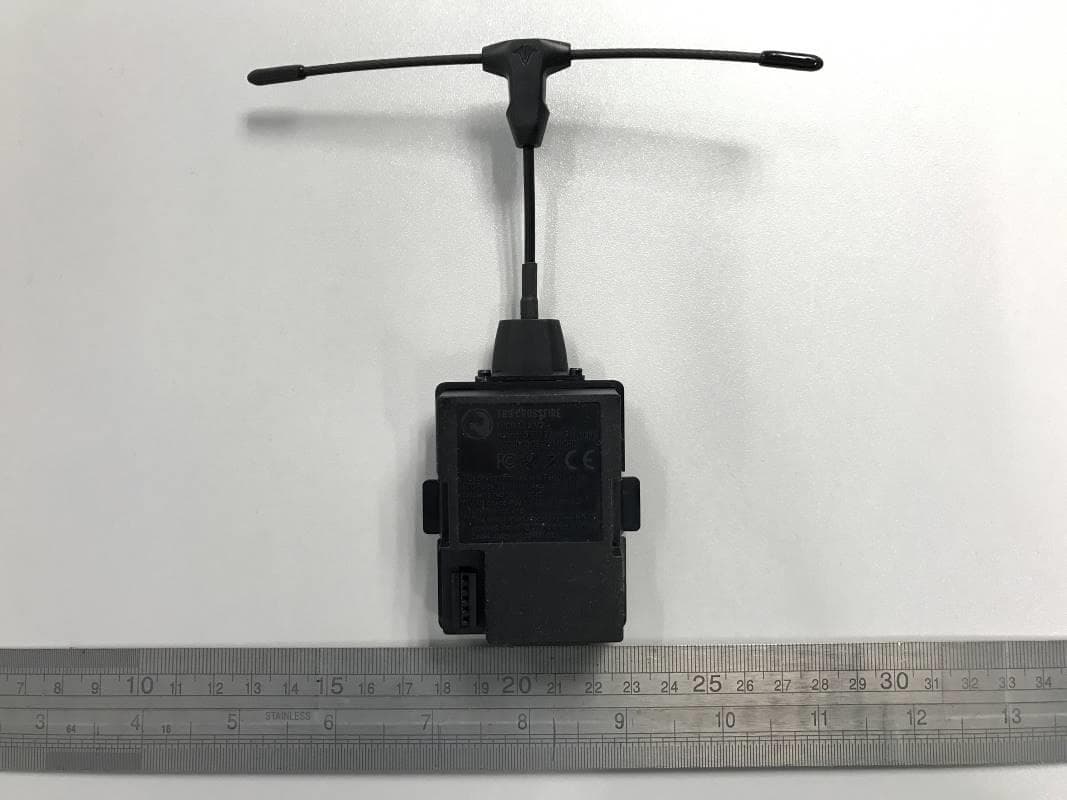
Click to zoom
Application Details
- Equipment Class
- DTS - Digital Transmission System
- Date of Grant
- Dec 18, 2020
- Application Purpose
- Original Equipment
- Date of Application
- Dec 17, 2020
- Equipment Note
- 915MHz and 2.4GHz Wi-Fi Transmitter Module (Transceiver)
- Frequency Range
- 2412.00000000 - 2462.00000000
- Company
- TBS Avionics Limited
- Country
- China
Documents & Files
Document Text
Text extracted from the exhibit documents filed with the FCC. Open a document above to read the original.
Users Manual
TBS CROSSFIRE R/C SystemRevision 2020-02-21 Adaptive Long Range Remote Control System The TBS CROSSFIRE (XF) system is a R/C link system made for FPV enthusiasts. It features unheard of range without sacrificing basic functionality such as being immune to interference from onboard equipment, low latency control or two-way communications including telemetry functionality. Key features •Long range, adaptive and robust remote control system for your aircraft •Immune to on-board noise •Two-way communication link with real-time link vitals and telemetry •Self-healing frequency hopping link •Receiver beacon mode to recover your downed aircraft •Super easy binding and configuration via built-in OLED display, OpenTX LUA or TBS TANGO remote •Low latency control for perfect immersive feeling •Free output mappable 8 output diversity with integrated backup battery or super tiny receiver ( 4g weight only ) both with up to 12 channel PPM •Ability to fly with multiple friends at the same time (10 or more) •Dynamic self-selecting or selectable RF power from 10mW to 1W (local restrictions apply) •Dedicated head-tracking input option for full FPV immersion •Transmitter LED shows link health, OLED display for built in configuration •Expansion port for future feature support 1 Table of content Attention Drone Racing Environment Crossfire LED Color Coding Overview Setup Connecting CROSSFIRE Standard Transmitter to radio Using JR-adapter Using Hitec/Graupner/JR-cable Using Futaba-cable Using custom PPM cable CRSF with other radios Connecting CROSSFIRE Micro transmitter to radio Push button functionality Connecting CROSSFIRE Diversity receiver Connecting CROSSFIRE Micro receiver Connecting CROSSFIRE Nano receiver Binding Auto bind Head-tracking Set failsafe BST Connectivity with TBS equipment Controlling UNIFY PRO VTX with SmartAudio Antenna Operation Status display Up- and downlink status Find mode Direction finder How does find mode work Testing find mode 2 Preparations Simulating flight Simulating a Crash Search and rescue Link regained Transmitter LED status indicator Receiver LED status indicator Real-time telemetry using app link Configuration Standard transmitter configuration Micro transmitter configuration Receiver PWM or PPM servo output Receiver SBUS output Receiver RSSI or/and LQ output Serial bridge MAVLink MAVLink APM Disable telemetry CRSF DSMX SmartAudio Transmission power Dynamic transmission power Transmission frequency Operating modes RF Profiles MyVTX CRSF Connectivity with flight controller (COLIBRI) Minimum requirements Wiring layout 3 Setting up radio for CRSF Setting up receiver for CRSF Configuring BetaFlight for CRSF protocol Discovering telemetry data sensors Configuration of CORE PRO / CROSSFIRE RX with LUA Scripts or the TBS TANGO Requirements Setup Telemetry Firmware upgrade Installing TBS Agent Emergency update FAQ Good practices FCC statement FCC ID of TBS Crossfire Products 4 Specifications Type: Long Range Two-Way Remote Control System Band: Europe: 868 MHz SRD Band America: 915 MHz ISM Band RF power Radio Signal & Telemetry downlink: Micro TX: Selectable 25mW and 100mW (250mW with FW 2.40 or later) Standard TX: Selectable 10mW to 500mW, additional 1W available with external power connected via XT30 socket Diversity, Micro and Nano RX: 40mW Receiver sensitivity: Up to -130dBm Antenna: TX: 1x omnidirectional dipole antenna RX: 2x omnidirectional dipole antennas, flexible antenna (Micro and Nano RX) R/C Channels: 8 (Diversity)/ 4(6) (Micro/Nano RX) PWM (freely mappable ) or up to 12-channel PPM stream outputs, standard 2.54mm servo connectors Radio compatibility: Any radio with PPM stream output ( absolute max. ratings: -0.3V - 15V ) JR Adapter for easy install on JR, FrSky and similar radios Interface: Micro TX: RGB LED light, push button, configuration via CRSF (TBS TANGO, OpenTX ect. ) Standard TX: 1.3-inch OLED display and joystick for configuration, binding and link stats, real-time telemetry link to any computer, tablet or phone and Micro-USB for firmware upgrade Recovery mode: Diversity RX: Beacon-mode, receiver backup LiPo battery - operating time of approx. 2 days Failsafe: Pre-set servo positions or stops outputting servo pulse - selectable in configuration menu or via push button Operating range: Variable depending on output power and radio environment Input power: TX: +3.5 to 12.6V via RC or HT 3-pin input connector, External 2S to 3S LiPo via XT30 connector (standard RX only) RX: +4.5V to 8.4V All reverse-polarity protected Power consumption: TX: 1.1W, at 25mW TX: 3.2W, at Max Tx power output Diversity RX: 1.5W / Micro/Nano RX: 1W Ports: Diversity RX: 1x BST (the CROSSFIRE RX does not power the BST line), 8x Servo connectors - Micro RX: V1: 1x Servo, 1x BST / V2: 4x Servo, 1x BST - Nano RX: 2x Pin-headers for 1x BST and 4x Servo Working temperature: 0 - 40°C Size: Standard TX: 150 x 80 x 20 mm, Micro TX: 73 x 56 x 35 mm Diversity RX: 30 x 50 x 12 mm, Micro RX: 40 x 14 x 9.5mm Weight: Micro TX: 38 grams Standard TX: 340 grams, Diversity RX: 25 grams, Micro RX: 3.2 grams Kit contents: 1x TBS CROSSFIRE TX transceiver unit, 1x TBS CROSSFIRE RX transceiver unit, 1x JR-adapter module, 1x Futaba-cable, 1x JR-cable, 1x custom-cable, 1x XT30 cable 5 Attention A general rule for RC aircrafts is that they must be controlled always under sight of view, check your RC regulation to keep up to date with regulations. Drone Racing Environment Crossfire Firmware V3.23 and above incorporates Racing Spec Firmware designed for race directors to effectively manage power output on CROSSFIRE for drone racing. When using TBS CROSSFIRE control link, it is a requirement that all pilots use exactly the same power output. Use of CROSSFIRE has the same requirement as management of video transmission power output when it comes to racing. Recommended power output is generally 100mW, however in some countries the maximum will be 25mW. Please check your countries regulations. The New LED Color Sy…
Text truncated - open the document above for the full version.
External Photos
Test Report No.: 60393192 001 Appendix 3 Page 1 of 3 Appendix 3 EUT External Photos Test Report No.: 60393192 001 Appendix 3 Page 2 of 3 FCC ID: QOS-TXMICRO External View External View Test Report No.: 60393192 001 Appendix 3 Page 3 of 3 External View External View
ID Label/Location Info
This device complies with Part 15 of the FCC Rules. Operation is subject to the following two conditions: (1) This device may not cause harmful interference, and (2) This device must accept any interference received, including interference that may cause undesired operation. TBS CROSSFIRE - MICRO TX FCC ID label Product Name:TBS CROSSFIRE Model No.:MICRO TX FCC ID: QOS-TXMICRO Rating: 3.5 - 13V 2W max. This device complies with Part 15 of the FCC Rules. Operation is subject to the following two conditions: (1) This device may not cause harmful interference, and (2) This device must accept any interference received, including interference that may cause undesired operation. Product Name:TBS CROSSFIRE Model No.:MICRO TX FCC ID: QOS-TXMICRO Rating: 3.5 - 13V 2W max.
Internal Photos
Test Report No.: 60393192 001 Appendix 4 Page 1 of 5 Appendix 4 EUT Internal Photos Test Report No.: 60393192 001 Appendix 4 Page 2 of 5 FCC ID: QOS-TXMICRO Internal View Internal View Test Report No.: 60393192 001 Appendix 4 Page 3 of 5 Internal View Internal View Test Report No.: 60393192 001 Appendix 4 Page 4 of 5 Internal View Internal View Test Report No.: 60393192 001 Appendix 4 Page 5 of 5 Internal View
RF Exposure Info
FCC SAR Test Report Report No.ES20924051E Page 1 of 37 Ver.1.0 FCC SAR Test Report Report No. : ES200924051E Applicant : TBS Avionics Limited Address : 9/F, Tungtex Building, 203 Wai Yip Street, Kwun Tong, Hong Kong, China Product : TBS CROSSFIRE FCC ID : QOS-TXMICRO Brand : N/A Model No. : MICRO TX Standards : FCC 47 CFR Part 2 (2.1093) / IEEE C95.1:1992 / IEEE 1528:2013 KDB 865664 D01 v01r04 / KDB 865664 D02 v01r02 KDB 248227 D01 v02r02 / KDB 447498 D01 v06 Sample Received Date : September 25, 2020 Date of Testing : October 21, 2020 to November 2, 2020 CERTIFICATION: The above equipment have been tested by EMTEK (SHENZHEN) CO., LTD. Bldg 69, Majialong Industry Zone, Nanshan District, Shenzhen, Guangdong, China, and found compliance with the requirement of the above standards. The test record, data evaluation & Equipment Under Test (EUT) configurations represented herein are true and accurate accounts of the measurements of the sample’s SAR characteristics under the conditions specified in this report. It should not be reproduced except in full, without the written approval of our laboratory. The client should not use it to claim product certification, approval, or endorsement by A2LA or any government agencies. Prepared by : Lance Li/Editor Reviewer : Joe Xia/Supervisor Approve & Authorized Signer : Lisa Wang/Manager This report is for your exclusive use. Any copying or replication of this report to or for any other person or entity, or use of our name or trademark, is permitted only with our prior written permission. This report sets forth our findings solely with respect to the test samples identified herein. The results set forth in this report are not indicative or representative of the quality or characteristics of the lot from which a test sample was taken or any similar or identical product unless specifically and expressly noted. Our report includes all of the tests requested by you and the results thereof based upon the information that you provided to us. You have 60 days from date of issuance of this report to notify us of any material error or omission caused by our negligence, provided, however, that such notice shall be in writing and shall specifically address the issue you wish to raise. A failure to raise such issue within the prescribed time shall constitute your unqualified acceptance of the completeness of this report, the tests conducted and the correctness of the report contents. Unless specific mention, the uncertainty of measurement has been explicitly taken into account to declare the compliance or non-compliance to the specification. $二维码$ FCC SAR Test Report Report No.ES20924051E Page 2 of 37 Ver.1.0 Table of Contents Release Control Record ............................................................................................................................................................... 3 1. Summary of Maximum SAR Value ....................................................................................................................................... 4 2. Description of Equipment Under Test ................................................................................................................................. 5 DC 7.6V .......................................................................................................................................................................................... 5 3. SAR Measurement System ................................................................................................................................................... 6 3.1 Definition of SpecificAbsorptionRate (SAR) ................................................................................................................. 6 3.2 SPEAG DASY System ................................................................................................................................................. 6 3.2.1 Robot .................................................................................................................................................................. 7 3.2.2 Probes ................................................................................................................................................................ 8 3.2.3 Data Acquisition Electronics (DAE) .................................................................................................................... 8 3.2.4 Phantoms ........................................................................................................................................................... 9 3.2.5 Device Holder ................................................................................................................................................... 10 3.2.6 System Validation Dipoles ................................................................................................................................ 10 3.2.7 Tissue Simulating Liquids ................................................................................................................................. 11 3.3 SAR System Verification ............................................................................................................................................ 14 3.4 SAR Measurement Procedure ................................................................................................................................... 15 3.4.1 Area & Zoom Scan Procedure ......................................................................................................................... 15 3.4.2 VolumeScan Procedure .................................................................................................................................... 15 3.4.3 Power Drift Monitoring ...................................................................................................................................... 16 3.4.4 Spatial Peak SAR Evaluation ............................…
Text truncated - open the document above for the full version.
RF Exposure Info
FCC SAR Test Report Report No.ES200924051E Page 1 of 37 Ver.1.0 Appendix A. SAR Plots of System Verification The plots for system verificationwith largest deviation for each SAR system combination are shown as follows. FCC SAR Test Report Report No.ES200924051E Page 2 of 37 Ver.1.0 Appendix B. SAR Plots of SAR Measurement The SAR plots for highest measured SAR in each exposure configuration, wireless mode and frequency band combination are shown as follows. FCC SAR Test Report Report No.ES200924051E Page 3 of 37 Ver.1.0 Appendix C. Calibration Certificate for Probe and Dipole The calibration certificates are shown as follows. FCC SAR Test Report Report No.ES200924051E Page 4 of 37 Ver.1.0 Appendix D. Photographs of EUT and Setup
RF Exposure Info
Test Laboratory: Shenzhen EMTEK Co.,Ltd.Date: 2020/10/22 System Check_B2450 DUT: Dipole 2450 MHz; Type:D2450V2; SN:835 Communication System: CW; Frequency: 2450 MHz;Duty Cycle: 1:1 Medium: B2450 Medium parameters used: f = 2450 MHz; σ = 2.028 S/m; ε r = 52.823; ρ = 1000 kg/m 3 Ambient Temperature:22.5 °C; Liquid Temperature:21.6 °C DASY5 Configuration: - Probe: EX3DV4 - SN3970; ConvF(7.96, 7.96, 7.96); Calibrated: 2020/2/8; - Sensor-Surface: 1.4mm (Mechanical Surface Detection) - Electronics: DAE4 Sn1418; Calibrated: 2020/1/8 - Phantom: ELI v5.0; Type: QDOVA002AA; Serial: TP:1231 - Measurement SW: DASY52, Version 52.8 (7); SEMCAD X Version 14.6.10 (7164) Pin=250mW/Area Scan (61x81x1): Interpolated grid: dx=1.200 mm, dy=1.200 mm Maximum value of SAR (interpolated) = 26.8 W/kg Pin=250mW/Zoom Scan (5x5x7)/Cube 0: Measurement grid: dx=8mm, dy=8mm, dz=5mm Reference Value = 106.4 V/m; Power Drift = 0.08 dB Peak SAR (extrapolated) = 31.7 W/kg SAR(1 g) = 12.6 W/kg; SAR(10 g) = 5.92 W/kg Maximum value of SAR (measured) = 25.9 W/kg Test Laboratory: Shenzhen EMTEK Co.,Ltd.Date: 2020/11/2 System Check_B835 DUT: Dipole:835 MHz; Type:D835V2; SN:4d029 Communication System: CW; Frequency: 835 MHz;Duty Cycle: 1:1 Medium: B835 Medium parameters used: f = 835 MHz; σ = 0.992 S/m; ε r = 55.615; ρ = 1000 kg/m 3 Ambient Temperature:22.5 °C; Liquid Temperature:21.6 °C DASY5 Configuration: - Probe: EX3DV4 - SN3970; ConvF(10.3, 10.3, 10.3); Calibrated: 2020/2/8; - Sensor-Surface: 2mm (Mechanical Surface Detection) - Electronics: DAE4 Sn1418; Calibrated: 2020/1/8 - Phantom: ELI v5.0; Type: QDOVA002AA; Serial: TP:1231 - Measurement SW: DASY52, Version 52.8 (7); SEMCAD X Version 14.6.10 (7164) Pin=250mW/Area Scan (61x101x1): Interpolated grid: dx=1.500 mm, dy=1.500 mm Maximum value of SAR (interpolated) = 3.80 W/kg Pin=250mW/Zoom Scan (5x5x7)/Cube 0: Measurement grid: dx=8mm, dy=8mm, dz=5mm Reference Value = 63.928 V/m; Power Drift = -0.04 dB Peak SAR (extrapolated) = 4.40 W/kg SAR(1 g) = 2.49 W/kg; SAR(10 g) = 1.63 W/kg Maximum value of SAR (measured) = 3.79 W/kg
RF Exposure Info
Test Laboratory: Shenzhen EMTEK Co.,Ltd.Date: 2020/10/22 802.11b-Left-ch1 DUT: MICRO TX Communication System: 802.11b; Frequency: 2412 MHz;Duty Cycle: 1:1 Medium: B2450 Medium parameters used: f = 2412 MHz; σ = 1.924 S/m; ε r = 52.753; ρ = 1000 kg/m 3 Ambient Temperature:22.5 °C; Liquid Temperature:21.6 °C DASY5 Configuration: - Probe: EX3DV4 - SN3970; ConvF(7.96, 7.96, 7.96); Calibrated: 2020/2/8; - Sensor-Surface: 4mm (Mechanical Surface Detection) - Electronics: DAE4 Sn1418; Calibrated: 2020/1/8 - Phantom: ELI v5.0; Type: QDOVA002AA; Serial: TP:1231 - Measurement SW: DASY52, Version 52.8 (7); SEMCAD X Version 14.6.10 (7164) Left/Area Scan (91x121x1): Interpolated grid: dx=1.000 mm, dy=1.000 mm Maximum value of SAR (interpolated) = 0.224 W/kg Left/Zoom Scan (7x7x7)/Cube 0: Measurement grid: dx=5mm, dy=5mm, dz=5mm Reference Value = 5.850 V/m; Power Drift = 0.06 dB Peak SAR (extrapolated) = 0.411 W/kg SAR(1 g) = 0.117 W/kg; SAR(10 g) = 0.0456 W/kg Maximum value of SAR (measured) = 0.212 W/kg Test Laboratory: Shenzhen EMTEK Co.,Ltd.Date: 2020/11/2 Lora-top-ch1 DUT: MICRO TX Communication System: Lora; Frequency: 902.75 MHz;Duty Cycle: 1:1 Medium: B835 Medium parameters used: f = 902 MHz; σ = 0.976 S/m; ε r = 56.163; ρ = 1000 kg/m 3 Ambient Temperature:22.5 °C; Liquid Temperature:21.6 °C DASY5 Configuration: - Probe: EX3DV4 - SN3970; ConvF(10.6, 10.6, 10.6); Calibrated: 2020/2/8; - Sensor-Surface: 2mm (Mechanical Surface Detection) - Electronics: DAE4 Sn1418; Calibrated: 2020/1/8 - Phantom: ELI v5.0; Type: QDOVA002AA; Serial: TP:1231 - Measurement SW: DASY52, Version 52.8 (7); SEMCAD X Version 14.6.10 (7164) Top/Area Scan (71x111x1): Interpolated grid: dx=1.500 mm, dy=1.500 mm Maximum value of SAR (interpolated) = 1.58 W/kg Top/Zoom Scan (5x5x7)/Cube 0: Measurement grid: dx=8mm, dy=8mm, dz=5mm Reference Value = 22.680 V/m; Power Drift = 0.09 dB Peak SAR (extrapolated) = 2.11 W/kg SAR(1 g) = 1.15 W/kg; SAR(10 g) = 0.682 W/kg Maximum value of SAR (measured) = 1.45 W/kg
RF Exposure Info
FCC SAR Test Report Report No.ES200924051E Page 1 of 3 Ver.1.0 <Photographs of EUT> FCC SAR Test Report Report No.ES200924051E Page 2 of 3 Ver.1.0 2.4G WLAN ANT FCC SAR Test Report Report No.ES200924051E Page 3 of 3 Ver.1.0 <Photographs of SAR Setup> Front Face of EUT with 0 cm Gap(WLAN) Rear Face of EUT with 0cm Gap(WLAN) Left Side of EUT with 0 cm Gap(WLAN) Top Side of EUT with 0 cm Gap(Lora) Front Face of EUT with 0 cm Gap(Lora) Rear Face of EUT with 0cm Gap(Lora)
Test Report
www.tuv.com Test Report No.: 60393192 001 Date: 17.12.2020 Page 15 of 21 2462 2453.150 2470.850 17700 FCC 15.247(b)(3) – Maximum Peak Conducted Output Power Pass FCC Requirement: For systems using digital modulation in the 902-928 MHz, 2400-2483.5 MHz, and 5725- 5850MHz bands: 1 Watt (30dBm) Test Specification : ANSI C63.10 – 2013 Test date : 18.09.2020 Mode of operation : Tx mode Port of testing : Temporary antenna port Supply voltage : 7.6VDC Temperature : 24ºC Humidity : 50% Remark: Pre-scan has been conducted to determine the worst-case mode from all possible combinations betw een available modulations and data rate. The worst cases is found in 1Mbps, 6Mbps and 6.5Mbps respectively. 802.11b Frequency (MHz) Measured Output Power (dBm) Limit (W/dBm) Verdict 2412 17.455 1 / 30.0 Pass 2437 16.805 1 / 30.0 Pass 2462 16.517 1 / 30.0 Pass 802.11g Frequency (MHz) Measured Output Power (dBm) Limit (W/dBm) Verdict 2412 16.071 1 / 30.0 Pass 2437 15.845 1 / 30.0 Pass 2462 15.265 1 / 30.0 Pass 802.11n-HT20 Frequency (MHz) Measured Output Power (dBm) Limit (W/dBm) Verdict 2412 14.753 1 / 30.0 Pass 2437 15.177 1 / 30.0 Pass 2462 14.982 1 / 30.0 Pass
Contact Information
Applicant
Raphael Pirker(Manager)
Test Firm
TUV Rheinland Hong Kong LimitedSharon Li
Technical Specifications
| # | Rule Parts | Frequency Range | Power Output |
|---|---|---|---|
| 1 | 15C | 2.41 GHz - 2.46 GHz | 56.00 mW |
Other Applications from TBS Avionics Limited
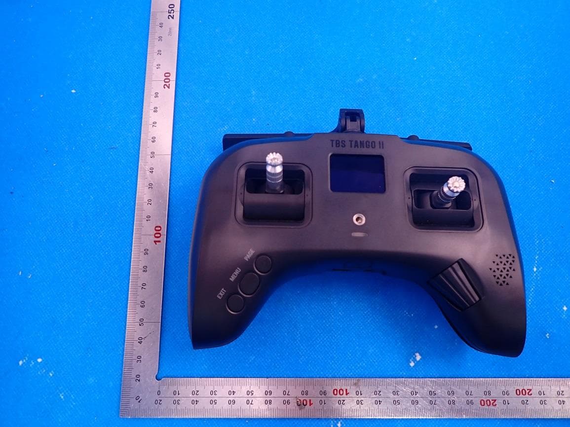
QOS-TANGO2
Aug 25, 2021Remote Control Radio
Equipment Class
DTS - Digital Transmission System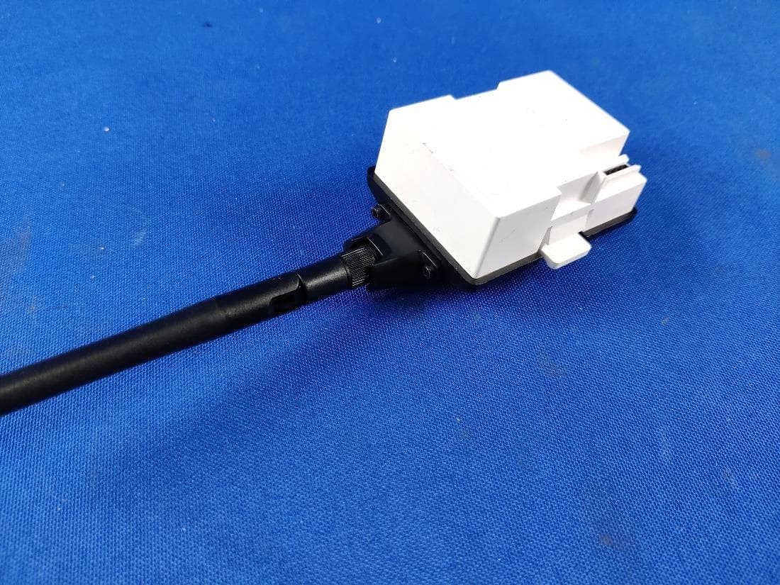
QOS-TCMICROTX
Apr 22, 2021MICRO TX
Equipment Class
DTS - Digital Transmission System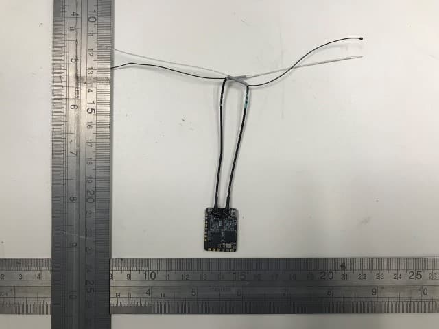
QOS-RXNANODIV
May 12, 2020915 MHz Receiver Module (Transceiver)
Equipment Class
DSS - Part 15 Spread Spectrum Transmitter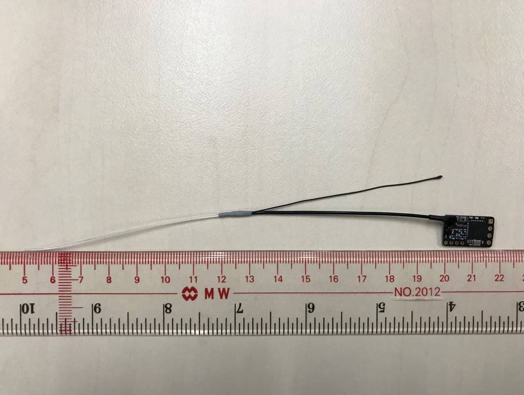
QOS-RXNANO
Feb 23, 2020915 MHz Receiver Module (Transceiver)
Equipment Class
DSS - Part 15 Spread Spectrum Transmitter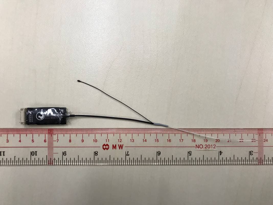
QOS-RXMICRO
Feb 23, 2020915 MHz Receiver Module (Transceiver)
Equipment Class
DSS - Part 15 Spread Spectrum Transmitter