QP7-802MABBWireless LAN 802.11a/b Dual Band Mini PCI Adapter
Actiontec Electronics (Taiwan) Inc.
Click to zoom
Application Details
- Equipment Class
- DTS - Digital Transmission System
- Date of Grant
- Mar 05, 2003
- Application Purpose
- Original Equipment
- Date of Application
- Mar 05, 2003
- Equipment Note
- Wireless LAN 802.11a/b Dual Band Mini PCI Adapter
- Frequency Range
- 2412.00000000 - 2462.00000000
- Country
- Taiwan
Documents & Files
Document Text
Text extracted from the exhibit documents filed with the FCC. Open a document above to read the original.
Users Manual
802MABB User’s Manual 1. Wireless LAN Basics Wireless LAN (Local Area Networks) systems offer a great number of advantages over a traditional, wired system. Wireless LANs (WLANs) are more flexible, easier to setup and manage and often more cost effective than their wired equivalence. Using radio frequency (RF) technology. WLANs transmit and receive data over the air, minimizing the need for wired connections. Thus, WLANs combine data connectivity with user mobility, and, through simplified configuration, enable movable LANs. With wireless LANs, users can access shared information without looking for a place to plug in and network managers can set up or augment networks without installing or moving wires. Wireless LANs offer the following productivity, convenience and cost advantages over traditional wired networks.• z Mobility – Wireless LAN systems can provide LAN users with access to real-time information anywhere in their organization. This mobility supports productivity and service opportunities not possible with wired networks. z Installation Speed and Simplicity – Installing a wireless LAN system can be fast and easy and can eliminate the need to pull cable through walls and ceilings. z Installation Flexibility – wireless technology allows the network to go where wires cannot go. z Reduced Cost-of-Ownership – While the initial investment required for wireless LAN hardware might be higher than the cost of wired LAN hardware, overall installation expenses and lifecycle costs will be significantly lower. Long- term cost benefits are greatest in dynamic environments requiring frequent moves, adds, and changes. z Scalability – Wireless LAN systems can be configured in a variety of topologies to meet the needs of specific applications and installations. Configurations are easily changed and range from peer-to-peer networks suitable for a small number of users to full infrastructure networks of thousands of users that allows roaming over a broad area. 2. Installation and Overview Here are some steps you will perform in establishing your wireless network connection: Installation Procedure of 802.11a/b WLAN MiniPCI Card 1. Insert the card into MiniPCI Slot. 2. Power on your computer and allow Windows to load fully. 3. The Windows will detect your Mini-PCI card and show the following screen. Please select “Install from a list or specific location (Advanced)” and click “Next” 4. Select “Search for the best driver in these locations (Recommended). Insert the given Installation Diskette and select “Include this location in the search” to find out your driver location. Click Next to run setup. And click “Next” 5. Now, the software you are installing for this hardware. Click “Continue Anyway” to continue. 6. Click “Finished”. The installation process are completely. 7. Connect the Access Point by right clicking on My Networking using the mouse. Select the Properties. 8. On the Network Connection screen, right click “Wireless Network connection Properties” and click “Properties”. 9. On the Wireless Networks tab, please check “Use Windows to configure my wireless network settings”. Then, select your Access Point on Available networks dialogue and click “Configure” Your Access Point will show on Preferred Network tab. Please select it and click ”Advanced” to choose Networks mode 10. As you see the red circle appear, that means you connect your Access Point successfully Federal Communication Commission Interference Statement This equipment has been tested and found to comply with the limits for a Class B digital device, pursuant to Part 15 of the FCC Rules. These limits are designed to provide reasonable protection against harmful interference in a residential installation. This equipment generates, uses and can radiate radio frequency energy and, if not installed and used in accordance with the instructions, may cause harmful interference to radio communications. However, there is no guarantee that interference will not occur in a particular installation. If this equipment does cause harmful interference to radio or television reception, which can be determined by turning the equipment off and on, the user is encouraged to try to correct the interference by one of the following measures: - Reorient or relocate the receiving antenna. - Increase the separation between the equipment and receiver. - Connect the equipment into an outlet on a circuit different from that to which the receiver is connected. - Consult the dealer or an experienced radio/TV technician for help. FCC Caution: Any changes or modifications not expressly approved by the party responsible for compliance could void the user's authority to operate this equipment. This device complies with Part 15 of the FCC Rules. Operation is subject to the following two conditions: (1) This device may not cause harmful interference, and (2) this device must accept any interference received, including interference that may cause undesired operation. IMPORTANT NOTE: FCC Radiation Exposure Statement: This equipment complies with FCC radiation exposure limits set forth for an uncontrolled environment. This equipment should be installed and operated with minimum distance 20cm between the radiator & your body. This transmitter must not be co-located or operating in conjunction with any other antenna or transmitter. This device is intended only for OEM integrators under the following conditions: 1) The antenna must be installed such that 20 cm is maintained between the antenna and users, and 2) The antenna should be integral if the end device is intended to be operated in 5.15 ~ 5.25GHz frequency range. As long as 2 conditions above are met, further transmitter test will not be required. However, the OEM integrator is still responsible for testing their end-product for any additional compliance requirements required with this module installed (for example, digital device emissions, PC peripheral requirements, etc.). IMPORTANT NOTE: In the event that these …
Text truncated - open the document above for the full version.
Cover Letter(s)
[email protected] www.adt.com.tw ADVANCE DATA TECHNOLOGY CORPORATION FEDERAL COMMUNICATIONS COMMISSION DECLARATION OF CONFORMITY (DoC) FOR THE FOLLOWING EQUIPMENT: PRODUCT NAME: Wireless LAN 802.11a/b Dual Band Mini PCI Adapter (Receiver Part) MODEL NO.: 802MABB TRADE NAME: Actiontec IS HEREWITH CONFIRMED AND FOUND TO COMPLY WITH THE REQUIREMENTS OF CFR 47 PART 15 REGULATION. THE RESULTS OF ELECTROMAGNETIC EMISSION EVALUATION ARE SHOWN IN THE REPORT NO.: D920129R03 THIS DEVICE COMPLIES WITH PART 15 OF THE FCC RULES. OPERATION IS SUBJECT TO THE FOLLOWING TWO CONDITIONS: (1) THIS DEVICE MAY NOT CAUSE HARMFUL INTERFERENCE AND, (2) THIS DEVICE MUST ACCEPT ANY INTERFERENCE RECEIVED, INCLUDING INTERFERENCE THAT MAY CAUSE UNDESIRED OPERATION. THE FOLLOWING LOCAL MANUFACTURER/IMPORTER IS RESPONSIBLE FOR THIS DECLARATION: ManufacturerUSA Local Representative Company name: ACTIONTEC ELECTRONICS(TAIWAN) INC. To Be Determined. Address: 7F,NO.178,MING CHUAN E. RD.SEC 3, TAIPEI TAIWAN R.O.C. Contact Person: William Lee Title: Engineer Manager Tel/Fax: Tel: +886 2-2514-7656 Fax: +886-2-8522-7156
Cover Letter(s)
American Telecommunications Certification Body Inc. 6731 Whittier Ave, McLean, VA 22101 February 25, 2003 RE: FCC ID: QP7-802MABB Attention: Ellis Wu / Alan Lane I have a few comments on this Application. 1. You have tested this device as a limited modular approval. However, you have provided an FCC ID label information for a modular approval. Please note that for Limited Modular Approvals inside a specific host the FCC ID label must go on that host, not on the card. Please remove the ID from the card and show where it will be placed on the Host. 2. This also means that the 2-condition statement required by 15.19 must be on the Host. 3. Since the FCC ID label will necessarily be on the Host for an LMA, this also means that you will have to remove the statement “The final end product must be labeled in a visible area with the following: “Contains TX FCC ID: QP7-802MABB” from the OEM installers manual. 4. The statement, “If the end product integrating this module is going to be operated in 5.15 ~5.25GHz frequency range, the warning statement in the user manual of the end product should include the restriction of operating this device in indoor could void the user’s authority to operate the equipment.” Is incorrect. The statement should be something like, “When used in the 5.15 – 5.25 GHz frequency range the following warning statement must appear in the users manual, ‘This device operates in the in 5.15 ~5.25GHz frequency range and is restricted to indoor use only.’” Please change the manual accordingly 5. FYI Please note that peak excursion is from the highest point on the upper trace to the lowest point on the lower trace within 1MHz. You have measured the lowest points on both traces. This is incorrect. While the device still appears to be compliant, your numbers are several dB too low for peak excursion. Please verify peak excursion data. 6. Please explain how the antenna connectors used in the device meet the requirements of 15.407(d) (Any U-NII device that operates in the 5.15-5.25 GHz band shall use a transmitting antenna that is an integral part of the device.) Dennis Ward mailto:[email protected] The items indicated above must be submitted before processing can continue on the above referenced application. Failure to provide the requested information may result in application termination. Correspondence should be considered part of the permanent submission and may be viewed from the Internet after a Grant of Equipment Authorization is issued. Please do not respond to this correspondence using the email reply button. In order for your response to be processed expeditiously, you must submit your documents through the AmericanTCB.com website. Also, please note that partial responses increase processing time and should not be submitted. Any questions about the content of this correspondence should be directed to the sender.
Cover Letter(s)
1 dward From: [email protected] Sent: Wednesday, March 05, 2003 7:59 PM To: [email protected] Cc: Alan Lane; [email protected]; [email protected]; [email protected] Subject: 回信: QP7-802MABB Dennis, Our response for your comments as below: For comment 1 to 5, revised lable, users manual and test report have been uploaked to ATCB website. For command 6, our client will glue the connector on the PCB board to meet the requirements of 15.407(d) Please kindly review it. Thanks and Best Regards 吳佳鑫 / Ellis Wu E-mail : [email protected] 誠信科技 / ADT Corp. TEL : +886 3 3270910 #24 FAX : +886 3 3270892 "dward" <[email protected] 收件人: <[email protected]> m> 副本抄送: "Alan Lane" <[email protected]> 主旨: QP7-802MABB 2003/02/25 04:06 PM 請回信 給 dward Hi Ellis / Alan Attached are the ATCB comments on the above app. Thanks Dennis
External Photos
Page 1 ANNEX PHOTOGRAPHS OF EUT Page 2 Page 3 Page 4 Page 5
Internal Photos
Page 6 Page 7 Page 8 Page 9 Page 10 Page 11 Page 12 Page 13 Page 14 Page 15 Page 16 Page 17
RF Exposure Info
ADT No: 920129R03 1 RF EXPOSURE REPORT REPORT NO.: RF920129R03 MODEL NO.: 802MABB ACCORDING: FCC Guidelines for Human Exposure IEEE C95.1 APPLICANT: Actiontec Electronics (Taiwan) Inc. ADDRESS: 3F, No. 170, Ming Chuan E. Rd., Sec. 3, Taipei, Taiwan, R.O.C. ISSUED BY: Advance Data Technology Corporation LAB LOCATION: 47 14th Lin, Chiapau Tsun, Linko, Taipei, Taiwan, R.O.C. 0528 ILAC MRA Lab Code: 200102-0 ADT No: 920129R03 2 RF Exposure Measurement (Mobile Device) 1. Introduction In this document, we try to prove the safety of radiation harmfulness to the human body for our product. The limit for Maximum Permissible Exposure (MPE) specified in FCC 1.1310 is followed. The Gain of the antenna used in this product is measured in a Fully Anechoic Chamber (FAC) calibrated for antenna measurement in ADT, and also the maximum total power input to the antenna is measured. Through the Friis transmission formula and the maximum gain of the antenna, we can calculate the distance, away from the product, where the limit of MPE is reached. Although the Friis transmission formula is a far field assumption, the calculated result of that is an over-prediction for near field power density. We will take that as the worst case to specify the safety range. 2. RF Exposure Limit According to FCC 1.1310: The criteria listed in the following table shall be used to evaluate the environmental impact of human exposure to radio-frequency (RF) radiation as specified in 1.1307(b) LIMITS FOR MAXIMUM PERMISSIBLE EXPOSURE (MPE) Frequency Range (MHz) Electric Field Strength (V/m) Magnetic Field Strength (A/m) Power Density (mW/cm 2 ) Average Time (minutes) (A)Limits For Occupational / Control Exposures 300-1500......F/3006 1500-100,000......56 (B)Limits For General Population / Uncontrolled Exposure 300-1500......F/15006 1500-100,000......1.030 F = Frequency in MHz ADT No: 920129R03 3 3. Friis Formula Friis transmission formula : Pd = (Pout*G) / (4*pi*r 2 ) where Pd = power density in mW/cm 2 Pout = output power to antenna in mW G = gain of antenna in linear scale Pi = 3.1416 R = distance between observation point and center of the radiator in cm Pd is the limit of MPE, 1 mW/cm 2 . If we know the maximum Gain of the antenna and the total power input to the antenna, through the calculation, we will know the distance r where the MPE limit is reached. Ref. : David K. Cheng, Field and Wave Electromagnetics, Second Edition, Page 640, Eq. (11-133). 4 EUT Operating condition The software provided by Manufacturer enabled the EUT to transmit and receive data at lowest, middle and highest channel individually. 5 Climate Condition The temperature and related humidity: 20 deg. C and 63 % RH 6. Classification This device is not fixed inside the host equipment, it is connected with host through wire. So it is easy to be re-located in the place where at least 20cm far away from the body of the user. Warning statement to the user for keeping at least 20cm or more separation distance with the antenna should be included in users manual. So, this device is classified as Mobile Device. ADT No: 920129R03 4 7 Test Results 7.1 Antenna Gain The maximum Gain measured in Fully Anechoic Chamber is 1.94dBi or 1.56 (numeric) for 2.4GHz and 2.15dBi or 1.64 (numeric) for 5GHz. 7.2 Output Power Into Antenna & RF Exposure Distance : For Part 802.11b: CHANNEL CHANNEL FREQUENCY (MHz) OUTPUT POWER TO ANTENNA (mW) MINIMUM ALLOWABLE DISTANCE ( r ) FROM SKIN (Centi-Meter) 1241234.832.08 6243749.092.47 11246248.312.45 For Part 802.11a: Normal Mode: CHANNEL CHANNEL FREQUENCY (MHz) OUTPUT POWER TO ANTENNA (mW) MINIMUM ALLOWABLE DISTANCE ( r ) FROM SKIN (Centi-Meter) 1518048.082.51 4524043.952.39 5526048.532.52 8532049.322.54 9574542.852.37 12580576.213.15 Turbo Mode: CHANNEL CHANNEL FREQUENCY (MHz) OUTPUT POWER TO ANTENNA (mW) MINIMUM ALLOWABLE DISTANCE ( r ) FROM SKIN (Centi-Meter) 1521042.362.35 2525047.642.49 3529043.452.38 4576048.532.52 5580043.452.38 The minimum allowable distance is very close to the enclosure of the antenna. So, the user has no need to worry about the harmfulness of radiation. But it is recommended to always keep, at least, 20cm separation distance with the antenna.
Test Report
FCC ID: QP7-802MABB Report No.: RF920129R031Issued: February 21, 2003 FCC TEST REPORT REPORT NO.: RF920129R03 MODEL NO.: 802MABB RECEIVED: Jan. 29, 2003 TESTED: Feb. 7 ~ Feb. 11, 2003 APPLICANT: Actiontec Electronics (Taiwan) Inc. ADDRESS: 3F, No. 170, Ming Chuan E. Rd., Sec. 3, Taipei, Taiwan, R.O.C. ISSUED BY: Advance Data Technology Corporation LAB LOCATION: 47 14 th Lin, Chiapau Tsun, Linko, Taipei, Taiwan, R.O.C. This test report consists of 145 pages in total. It may be duplicated completely for legal use with the approval of the applicant. It should not be reproduced except in full, without the written approval of our laboratory. The client should not use it to claim product endorsement by CNLA, NVLAP or any government agencies. The test results in the report only apply to the tested sample. 0528 ILAC MRA Lab Code: 200102-0 FCC ID: QP7-802MABB Report No.: RF920129R032Issued: February 21, 2003 Table of Contents 1.CERTIFICATION .................................................................................................................... 5 2.SUMMARY OF TEST RESULTS............................................................................................ 6 3.GENERAL INFORMATION .................................................................................................... 8 3.1GENERAL DESCRIPTION OF EUT....................................................................................... 8 3.2DESCRIPTION OF TEST MODES....................................................................................... 10 3.3GENERAL DESCRIPTION OF APPLIED STANDARDS...................................................... 11 3.4DESCRIPTION OF SUPPORT UNITS................................................................................. 12 4.TEST TYPES AND RESULTS (FOR PART 802.11b)........................................................... 13 4.1CONDUCTED EMISSION MEASUREMENT....................................................................... 13 4.1.1LIMITS OF CONDUCTED EMISSION MEASUREMENT .................................................... 13 4.1.2TEST INSTRUMENTS ......................................................................................................... 13 4.1.3TEST PROCEDURES .......................................................................................................... 14 4.1.4DEVIATION FROM TEST STANDARD ................................................................................ 14 4.1.5TEST SETUP ....................................................................................................................... 15 4.1.6EUT OPERATING CONDITIONS......................................................................................... 15 4.1.7TEST RESULTS ................................................................................................................... 16 4.2RADIATED EMISSION MEASUREMENT............................................................................ 22 4.2.1LIMITS OF RADIATED EMISSION MEASUREMENT ......................................................... 22 4.2.2TEST INSTRUMENTS ......................................................................................................... 23 4.2.3TEST PROCEDURES .......................................................................................................... 24 4.2.4DEVIATION FROM TEST STANDARD ................................................................................ 24 4.2.5TEST SETUP ....................................................................................................................... 25 4.2.6EUT OPERATING CONDITIONS......................................................................................... 25 4.2.7TEST RESULTS ................................................................................................................... 26 4.36dB BANDWIDTH MEASUREMENT ................................................................................... 31 4.3.1LIMITS OF 6dB BANDWIDTH MEASUREMENT ................................................................ 31 4.3.2TEST INSTRUMENTS ......................................................................................................... 31 4.3.3TEST PROCEDURE ............................................................................................................32 4.3.4DEVIATION FROM TEST STANDARD ................................................................................ 32 4.3.5TEST SETUP ....................................................................................................................... 32 4.3.6EUT OPERATING CONDITIONS......................................................................................... 32 4.3.7TEST RESULTS ................................................................................................................... 33 4.4MAXIMUM PEAK OUTPUT POWER ................................................................................... 37 4.4.1LIMITS OF MAXIMUM PEAK OUTPUT POWER MEASUREMENT ................................... 37 4.4.2INSTRUMENTS.................................................................................................................... 37 4.4.3TEST PROCEDURES .......................................................................................................... 38 4.4.4DEVIATION FROM TEST STANDARD ................................................................................ 38 4.4.5TEST SETUP ....................................................................................................................... 38 4.4.6EUT OPERATING CONDITIONS......................................................................................... 38 FCC ID: QP7-802MABB Report No.: RF920129R033Issued: February 21, 2003 4.4.7TEST RESULTS ................................................................................................................... 39 4.5POWER SPECTRAL DENSITY MEASUREMENT...........................................…
Text truncated - open the document above for the full version.
Test Report
FCC ID: QP7-802MABB Report No.: RF920129R03100Issued: February 21, 2003 5.4 PEAK POWER EXCURSION MEASUREMENT 5.4.1 LIMITS OF PEAK POWER EXCURSION MEASUREMENT Frequency BandLimit 5.15 – 5.25 GHz13dB 5.25 – 5.35 GHz13dB 5.725 – 5.825 GHz13dB 5.4.2 TEST INSTRUMENTS Description & ManufacturerModel No.Serial No.Calibrated Until ROHDE&SCHWARZ SPECTRUM ANALYZER FSEK30100049July 24, 2003 NOTE: The calibration interval of the above test instruments is 12 months and the calibrations are traceable to NML/ROC and NIST/USA. FCC ID: QP7-802MABB Report No.: RF920129R03101Issued: February 21, 2003 5.4.3 TEST PROCEDURE 1. The transmitter output was connected to the spectrum analyzer. 2. Set the spectrum bandwidth span to view the entire spectrum. 3. Using peak detector and Max-hold function for Trace 1 (RB=1MHz, VB=3MHz) and 2 (RB=1MHz, VB=300KHz). 4. The largest difference between Trace 1 and Trace 2 in any 1MHz band on any frequency was recorded. 5.4.4 DEVIATION FROM TEST STANDARD No deviation 5.4.5 TEST SETUP 5.4.6 EUT OPERATING CONDITIONS The software provided by client to enable the EUT under transmission condition continuously at specific channel frequencies individually. EUT SPECTRUM FCC ID: QP7-802MABB Report No.: RF920129R03102Issued: February 21, 2003 5.4.7 TEST RESULTS EUT Wireless LAN 802.11a/b Dual Band Mini PCI Adapter MODEL 802MABB MODE Normal INPUT POWER (SYSTEM) 120Vac, 60 Hz ENVIRONMENTAL CONDITIONS 21deg. C, 68RH, 1005 hPa TESTED BY Ansen Lei CHANNEL CHANNEL FREQUENCY (MHz) PEAK POWER EXCURSION (dB) PEAK to AVERAGE EXCURSION LIMIT (dB) PASS/FAIL 151807.7613PASS 452407.8013PASS 552607.6813PASS 853208.1213PASS 957457.6113PASS 1258057.4713PASS FCC ID: QP7-802MABB Report No.: RF920129R03103Issued: February 21, 2003 CHANNEL 1 FCC ID: QP7-802MABB Report No.: RF920129R03104Issued: February 21, 2003 CHANNEL 4 FCC ID: QP7-802MABB Report No.: RF920129R03105Issued: February 21, 2003 CHANNEL 5 FCC ID: QP7-802MABB Report No.: RF920129R03106Issued: February 21, 2003 CHANNEL 8 FCC ID: QP7-802MABB Report No.: RF920129R03107Issued: February 21, 2003 CHANNEL 9 FCC ID: QP7-802MABB Report No.: RF920129R03108Issued: February 21, 2003 CHANNEL 12 FCC ID: QP7-802MABB Report No.: RF920129R03109Issued: February 21, 2003 EUT Wireless LAN 802.11a/b Dual Band Mini PCI Adapter MODEL 802MABB MODE Turbo INPUT POWER (SYSTEM) 120Vac, 60 Hz ENVIRONMENTAL CONDITIONS 21deg. C, 68RH, 1005 hPa TESTED BY Ansen Lei CHANNEL CHANNEL FREQUENCY (MHz) PEAK POWER EXCURSION (dB) PEAK to AVERAGE EXCURSION LIMIT (dB) PASS/FAIL 152108.4813PASS 252507.8313PASS 352908.0713PASS 457608.3613PASS 558007.6013PASS FCC ID: QP7-802MABB Report No.: RF920129R03110Issued: February 21, 2003 CHANNEL 1 FCC ID: QP7-802MABB Report No.: RF920129R03111Issued: February 21, 2003 CHANNEL 2 FCC ID: QP7-802MABB Report No.: RF920129R03112Issued: February 21, 2003 CHANNEL 3 FCC ID: QP7-802MABB Report No.: RF920129R03113Issued: February 21, 2003 CHANNEL 4 FCC ID: QP7-802MABB Report No.: RF920129R03114Issued: February 21, 2003 CHANNEL 5 FCC ID: QP7-802MABB Report No.: RF920129R03115Issued: February 21, 2003 5.5 PEAK POWER SPECTRAL DENSITY MEASUREMENT 5.5.1 LIMITS OF PEAK POWER SPECTRAL DENSITY MEASUREMENT Frequency BandLimit 5.15 – 5.25 GHz4dBm 5.25 – 5.35 GHz11dBm 5.725 – 5.825 GHz17dBm 5.5.2 TEST INSTRUMENTS Description & ManufacturerModel No.Serial No.Calibrated Until ROHDE&SCHWARZ SPECTRUM ANALYZER FSEK30100049July 24, 2003 NOTE: The calibration interval of the above test instruments is 12 months and the calibrations are traceable to NML/ROC and NIST/USA. FCC ID: QP7-802MABB Report No.: RF920129R03116Issued: February 21, 2003 5.5.3 TEST PROCEDURES 1. The transmitter output was connected to the spectrum analyzer. 2. Set RBW=1MHz, VBW=3MHz. The PPSD is the highest level found across the emission in any 1MHz band. 5.5.4 DEVIATION FROM TEST STANDARD No deviation 5.5.5 TEST SETUP 5.5.6 EUT OPERATING CONDITIONS Same as 5.3.6 EUT SPECTRUM ANALYZER FCC ID: QP7-802MABB Report No.: RF920129R03117Issued: February 21, 2003 5.5.7 TEST RESULTS EUT Wireless LAN 802.11a/b Dual Band Mini PCI Adapter MODEL 802MABB MODE Normal INPUT POWER (SYSTEM) 120Vac, 60 Hz ENVIRONMENTAL CONDITIONS 21deg. C, 68RH, 1005 hPa TESTED BY Ansen Lei CHANNEL NUMBER CHANNEL FREQUENCY (MHz ) RF POWER LEVEL IN 1 MHz BW (dBm) MAXIMUM LIMIT (dBm) PASS/FAIL 151800.614PASS 45240-0.214PASS 552600.5411PASS 853200.4611PASS 95745-0.8917PASS 1258050.0617PASS FCC ID: QP7-802MABB Report No.: RF920129R03118Issued: February 21, 2003 CHANNEL 1 FCC ID: QP7-802MABB Report No.: RF920129R03119Issued: February 21, 2003 CHANNEL 4 FCC ID: QP7-802MABB Report No.: RF920129R03120Issued: February 21, 2003 CHANNEL 5 FCC ID: QP7-802MABB Report No.: RF920129R03121Issued: February 21, 2003 CHANNEL 8 FCC ID: QP7-802MABB Report No.: RF920129R03122Issued: February 21, 2003 CHANNEL9 FCC ID: QP7-802MABB Report No.: RF920129R03123Issued: February 21, 2003 CHANNEL 12 FCC ID: QP7-802MABB Report No.: RF920129R03124Issued: February 21, 2003 EUT Wireless LAN 802.11a/b Dual Band Mini PCI Adapter MODEL 802MABB MODE Turbo INPUT POWER (SYSTEM) 120Vac, 60 Hz ENVIRONMENTAL CONDITIONS 21deg. C, 68RH, 1005 hPa TESTED BY Ansen Lei CHANNEL NUMBER CHANNEL FREQUENCY (MHz ) RF POWER LEVEL IN 1 MHz BW (dBm) MAXIMUM LIMIT (dBm) PASS/FAIL 15210-3.514PASS 25250-2.704PASS 35290-3.0911PASS 45760-2.9017PASS 55800-3.0217PASS FCC ID: QP7-802MABB Report No.: RF920129R03125Issued: February 21, 2003 CHANNEL 1 FCC ID: QP7-802MABB Report No.: RF920129R03126Issued: February 21, 2003 CHANNEL 2 FCC ID: QP7-802MABB Report No.: RF920129R03127Issued: February 21, 2003 CHANNEL 3 FCC ID: QP7-802MABB Report No.: RF920129R03128Issued: February 21, 2003 CHANNEL 4 FCC ID: QP7-802MABB Report No.: RF920129R03129Issued: February 21, 2003 CHANNEL 5 FCC ID: QP7-802MABB Report No.: RF920129R03130Issued: February 21, 2003 5.6 FREQUENCY STABILITY 5.6.1 LIMITS OF FREQUENCY STABILITY MEASUREMENT The frequency tolerance of the carrier signal shall be maintained within +/- 0.02% of the opera…
Text truncated - open the document above for the full version.
Test Setup Photos
FCC ID: QP7-802MABB Report No.: RF920129R03144Issued: February 21, 2003 6. PHOTOGRAPHS OF THE TEST CONFIGURATION CONDUCTED EMISSION TEST FCC ID: QP7-802MABB Report No.: RF920129R03145Issued: February 21, 2003 RADIATED EMISSION TEST
Contact Information
Applicant
Peggy Chen(Manager)
Technical Contact
Advance Data Technology CorporationEllis Wu
[email protected]886-3-327-0910
13-1, Lane19, WenShan 3rd ., St., · Taoyuan · Taiwan
Test Firm
Bureau Veritas CPS (H.K.) Ltd. Taoyuan BranchTommy Wu
Technical Specifications
| # | Rule Parts | Frequency Range | Power Output |
|---|---|---|---|
| 1 | 15C | 2.41 GHz - 2.46 GHz | 49.00 mW |
Other Applications from Actiontec Electronics (Taiwan) Inc.
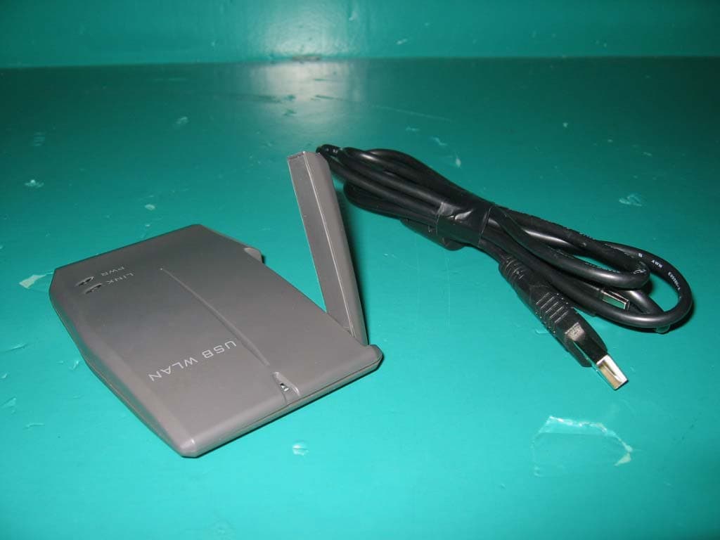
QP7802U1G1
Nov 10, 2004802.11G WLAN USB Adapter
Equipment Class
DTS - Digital Transmission System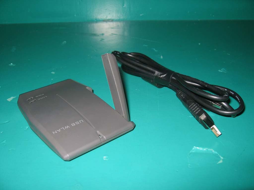
QP7802UIG1
Nov 10, 2004802.11g WLAN USB Adapter
Equipment Class
DTS - Digital Transmission System
QP7-802MR
Jul 20, 2003Mini PCI 802.11b Wireless LAN Card
Equipment Class
DTS - Digital Transmission System
QP7-802MRE
Jun 19, 2003802.11b Wireless LAN Mini-PCI Adapter
Equipment Class
DTS - Digital Transmission System
QP7-802MI3B
Dec 20, 2002802.11b Wireless LAN Mini-PCI Adapter
Equipment Class
DTS - Digital Transmission System