QP7-802MRE802.11b Wireless LAN Mini-PCI Adapter
Actiontec Electronics (Taiwan) Inc.
Click to zoom
Application Details
- Equipment Class
- DTS - Digital Transmission System
- Date of Grant
- Jun 19, 2003
- Application Purpose
- Original Equipment
- Date of Application
- Jun 19, 2003
- Equipment Note
- 802.11b Wireless LAN Mini-PCI Adapter
- Frequency Range
- 2412.00000000 - 2462.00000000
- Country
- Taiwan
Documents & Files
Document Text
Text extracted from the exhibit documents filed with the FCC. Open a document above to read the original.
Users Manual
802MR User’s Manual 1. Wireless LAN Basics Wireless LAN (Local Area Networks) systems offer a great number of advantages over a traditional, wired system. Wireless LANs (WLANs) are more flexible, easier to setup and manage and often more cost effective than their wired equivalence. Using radio frequency (RF) technology. WLANs transmit and receive data over the air, minimizing the need for wired connections. Thus, WLANs combine data connectivity with user mobility, and, through simplified configuration, enable movable LANs. With wireless LANs, users can access shared information without looking for a place to plug in and network managers can set up or augment networks without installing or moving wires. Wireless LANs offer the following productivity, convenience and cost advantages over traditional wired networks.• z Mobility – Wireless LAN systems can provide LAN users with access to real-time information anywhere in their organization. This mobility supports productivity and service opportunities not possible with wired networks. z Installation Speed and Simplicity – Installing a wireless LAN system can be fast and easy and can eliminate the need to pull cable through walls and ceilings. z Installation Flexibility – wireless technology allows the network to go where wires cannot go. z Reduced Cost-of-Ownership – While the initial investment required for wireless LAN hardware might be higher than the cost of wired LAN hardware, overall installation expenses and lifecycle costs will be significantly lower. Long- term cost benefits are greatest in dynamic environments requiring frequent moves, adds, and changes. z Scalability – Wireless LAN systems can be configured in a variety of topologies to meet the needs of specific applications and installations. Configurations are easily changed and range from peer-to-peer networks suitable for a small number of users to full infrastructure networks of thousands of users that allows roaming over a broad area. 2. Installation and Overview Here are some steps you will perform in establishing your wireless network connection: z Install Access Point at first. AP is needed in case of Infrastructure network mode. z Install software using the Installation Disktette. z Install network protocol(s) required to communicate on your network. Most likely you will need the TCP/IP protocol Here are some steps you will perform in installing your driver for AC97 Soft Modem. z Install driver using the Installation Diskette 3. Installation Procedure of 802.11b WLAN MiniPCI Card 1. Insert the card into MiniPCI Slot. 2. Power on your computer and allow Windows to load fully. 3. The Windows will detect your Mini-PCI card and show the following screen. Please click Next 4. Select Search for the best driver for your device. (Recommended). And click Next 5. Insert the given Installation Diskette and select Specify a location to find out your driver location. Click Next to run setup. 6. Click Finished. The installation process are completely. 7. Click Yes to restart your computer. 8. Check for the 802.11b WLAN MiniPCI Card by right clicking on My Computer using the mouse. Select the Device manager and then Network Adapters. If you find the sign on the adapter, it shows the installation is not successful. If not, it means your setup is successfully. 3.1 Install network protocol(s) required to communicate on your network 9. Right click on the Network Neighborhood using the mouse. 10. Select Properties from the pop up menu. The network box appears and you see the three main tables: Configuration, Identification and Access control. 11. Click on the Configuration tab and then click on the Add button. Select Network component Type Box appears. Click on the Protocol then click the Add Button 12. Select Network Protocols box appears. From the list of manufactures, Click on Microsoft. From the list of network protocols list, select NetBEUI, then click OK 13. The NetBEUI protocol is now installed. After clicking on OK return back to Network Component Type box. 14. Repeat the Step 10 and 11 to add IPX/SPX protocol. 15. Repeat the step 10 and 11 to add TCP/IP protocol. 16. Click on TCP/IP option for setting the IP address for your computer. You can select either Static or DHCP setting. If you use the static IP setup then enter the IP value, Subnet masking, DNS, Domain/Workgroup name, and Gateway address values. After setting these parameter appropriately, click OK to return to Network component type. 17. Now you can select the File and Printer Sharing options as well as the Access to your computer other users connected to the network by setting the computer sharing Option. Click on OK 18. Screen message do want to restart your computer will pop up. Select Yes. It will shut down your computer and will restart. 4. Installation Procedure of 56K Mini-PCI Fax Modem Card 1. Start Windows 2. Windows will immediately display the New Hardware Wizard and identify the modem. Click the Next button. 3. Select the option Search for the best driver for your device (Recommended) and then click the Next button 4. Please choose Specify a location & insert the installation disk into Floppy or CD-ROM. Windows will search for driver & display the following screen Click Next button 5. After the drivers are installed, click “Finish” After Windows re-starts, you can check your modem by following instructions to checking your 802MR if setup successfully. 6. Go to My Computer Control Panel Modem The Modem Properties screen will be displayed. 7. Select Diagnostics , choose COM3 Agere systems AC97 Modem and click on More Info... 7. The Modem will respond to the following message as screen showed that means your modem installed successfully. Federal Communication Commission Interference Statement This equipment has been tested and found to comply with the limits for a Class B digital device, pursuant to Part 15 of the FCC Rules. These limits are designed to provide reasonable protection against harmful interference…
Text truncated - open the document above for the full version.
Cover Letter(s)
FCC ID: QP7-802MRE ADT No.920505R03 Modular Approval Request Letter Advance Data Technology June. 03, 2003 Dear Application Examiner, Actiontec Electronics (Taiwan) Inc.,802.11b Wireless LAN Mini-PCI Adapter, FCC ID: QP7-802MRE, would like to have your authorization for Limited Module Approval specific to the portable device such as laptop. The requirements of Public Notice DA00-1407 have been met and shown on the following statements. 1. “The modular transmitter must have its own RF shielding.”: The radio portion of this module has been shielded, please see exhibition External Photo. 2. “The modular transmitter must have buffered modulation/data inputs.” The EUT has buffered data inputs, it is integrated in chip RTL8180-QFP128. 3. “The modular transmitter must have its own power supply regulation.” There is a regulator in the DC input port, the part number is AME8812. 4. “The modular transmitter must comply with the antenna requirements of section 15.203 and 15.204(C).” The EUT meets the FCC antenna requirements. The spurious emission, unique antenna connector and photo of antennas are shown in the test report. 5. “The modular transmitter must be tested in a stand-alone configuration. Due to the modular be specified to laptop model brand:ELITE / Model:G55X, so the EUT was tested in the full system configuration. Please see section Photographs of Test Configuration in the test report. 6. “The modular transmitter must be labeled with its own FCC ID number.” Please see exhibition Label Sample for the FCC ID of this module. And also in the exhibition Users Manual, there are instructions give to the OEM on how to label the end product. FCC ID: QP7-802MRE ADT No.920505R03 7. “The modular transmitter must comply with any specific rule or operating requirements applicable to the transmitter and the manufacturer must provide adequate instructions along with the module to explain any such requirements.” The EUT is compliant with all applicable FCC rules. Detail instructions for maintaining compliance are given in the Users Manual. 8. “The modular transmitter must comply with any applicable RF exposure requirements.” The EUT is compliant with all applicable RF exposure requirements. RF Exposure is addressed in the RF exposure exhibition. Please contact me if you have any further questions. Thanks for your attention. Best Regards, Dr. Alan Lane Manager of R&TTE Division Advance Data Technology
External Photos
Page 1 ANNEX PHOTOGRAPHS OF EUT Page 2 Page 3 Page 4 Page 5 Page 6 Page 7 Page 8 Page 9 Page 10 Page 11 Page 12 Page 13 Page 14 Page 15
External Photos
Page 1 ANNEX PHOTOGRAPHS OF EUT Page 2 Page 3 Page 4 Page 5
ID Label/Location Info
QP7-802MRE
Internal Photos
Page 6 Page 7 Page 8 Page 9 Page 10 Page 11 Page 12 Page 13 Page 14 Page 15
Operational Description
FCC ID: QP7-802MRE ADT No.920505R03 Operational Description The transmitter of the EUT (802.11b Wireless LAN Mini-PCI Adapter) is powered by notebook. The antenna is PIFA antenna with URL connector. The other instruction, please have a look at the users manual. DSSS Information This device is Direct Sequence Spread Spectrum, the data is mixed by pseudorandom code which is an orthogonal code. The mixed data is digital modulated by BPSK and QPSK technique depends on the data rates. The CCK coding is applied for increasing the data rate, and also the processing gain will be increased. The bit rates are 1,2,5.5,11Mbps, the symbol rates are 1,1,1.375,1.375Mbps, the chip rates are always 11Mbps. So, the Chip/symbol is 11,11,8 and 8 respectively. Although is higher bit rate, the processing gain is lower than 10, but the CCK coding used in higher bit rate will provide 2.2dB coding gain.
RF Exposure Info
FCC ID: QP7-802MRE ADT No.: 920505R03 FCC TEST REPORT REPORT NO.: RF920505R03 MODEL NO.: 802MR / 802MR-W ACCORDING: FCC Guidelines for Human Exposure IEEE C95.1 APPLICANT: Actiontec Electronics (Taiwan) Inc. ADDRESS: 7F,NO.170,MING CHUAN E. RD.SEC 3, TAIPEI TAIWAN R.O.C ISSUED BY: Advance Data Technology Corporation LAB LOCATION: 47 14th Lin, Chiapau Tsun, Linko, Taipei, Taiwan, R.O.C. 0528 ILAC MRA Lab Code: 200102-0 FCC ID: QP7-802MRE ADT No.: 920505R03 RF Exposure Measurement (Portable Device) 1. Introduction 2.4GHz frequency band is regarded specially as a dangerous band for its heating harmfulness to the human body. That’s why microwave oven is operating in this frequency band. The manufacturer whose product is working in this frequency band is obligatory to prove the harmfulness of his product. In this document, we try to prove the safety of radiation harmfulness to the human body for our product. The limit for Maximum Permissible Exposure (MPE) specified in FCC 1.1310 is followed. The Gain of the antenna used in this product is measured in a Fully Anechoic Chamber (FAC), and the maximum total power input to the antenna is measured. Through the Friis transmission formula and the maximum gain of the antenna, we can calculate the distance, away from the product, where the limit of MPE is reached. 2. Classification The antenna of the product, under normal use condition, is at least 2.5cm away from the body of the user. Warning statement for keeping 2.5cm separation distance and the prohibition of operating next to a person has been printed on the user’s manual. So, this product is classified as the Portable Device. 3. RF Exposure Limit According to FCC 1.1310: The criteria listed in the following table shall be used to evaluate the environmental impact of human exposure to radio-frequency (RF) radiation as specified in 1.1307(b). FCC ID: QP7-802MRE ADT No.: 920505R03 LIMITS FOR MAXIMUM PERMISSIBLE EXPOSURE (MPE) Frequency Range (MHz) Electric Field Strength (V/m) Magnetic Field Strength (A/m) Power Density (mW/cm 2 ) Average Time (minutes) (A)Limits For Occupational / Control Exposures 30-300 61.4 0.163 1.0 6 300-1500 ... ... F/300 6 1500-100,000 ... ... 5 6 (B)Limits For General Population / Uncontrolled Exposure 30-300 27.5 0.073 0.2 30 300-1500 ... ... F/1500 30 1500-100,000 ... ... 1.0 30 F = Frequency in MHz 4. Friis Formula Friis transmission formula : Pd = (Pout*G) / (4*pi*r 2 ) where Pd = power density in mW/cm 2 Pout = output power to antenna in mW G = gain of antenna in linear scale Pi = 3.1416 R = distance between observation point and center of the radiator in cm Pd is the limit of MPE, 1 mW/cm 2 . If we know the maximum Gain of the antenna and the total power input to the antenna, through the calculation, we will know the MPE value at distance r. Ref. : David K. Cheng, Field and Wave Electromagnetics, Second Edition, Page 640, Eq. (11-133). 5. EUT Operating condition The software provided by Manufacturer enabled the EUT to transmit and receive data at lowest, middle and highest channel individually. FCC ID: QP7-802MRE ADT No.: 920505R03 6. Test Results 6.1 Antenna Gain The maximum Gain measured in Fully Anechoic Chamber is 5.813dBi or 3.8132 (numeric). 6.2 Output Power Into Antenna & MPE value at distance 2.5cm : For 802.11b: CHANNEL CHANNEL FREQUENCY (MHz) OUTPUT POWER TO ANTENNA (mW) Power Density (mW/cm 2 ) Limit of Power Density (mW/cm 2 ) 1 2412 5.36 0.26 1.0 6 2437 5.52 0.27 1.0 11 2462 6.10 0.30 1.0 The minimum allowable distance is very close to the enclosure of the antenna and is very far away from the human being under normal use condition.
Test Report
FCC ID: QP7-802MRE Report No.: RF920505R03 1 Issued: June 12, 2003 FCC TEST REPORT REPORT NO.: RF920505R03 MODEL NO.: 802MR / 802MR-W RECEIVED: May. 05, 2003 TESTED: May. 17 ~ June. 03, 2003 APPLICANT: Actiontec Electronics (Taiwan) Inc. ADDRESS: 7F,NO.170,MING CHUAN E. RD.SEC 3, TAIPEI TAIWAN R.O.C ISSUED BY: Advance Data Technology Corporation LAB LOCATION: 47 14th Lin, Chiapau Tsun, Linko, Taipei, Taiwan, R.O.C. This test report consists of 52 pages in total. It may be duplicated completely for legal use with the approval of the applicant. It should not be reproduced except in full, without the written approval of our laboratory. The client should not use it to claim product endorsement by CNLA, NVLAP or any government agencies. The test results in the report only apply to the tested sample. 0528 ILAC MRA Lab Code: 200102-0 FCC ID: QP7-802MRE Report No.: RF920505R03 2 Issued: June 12, 2003 Table of Contents 1 CERTIFICATION ........................................................................................... 4 2 SUMMARY OF TEST RESULTS................................................................... 5 3 GENERAL INFORMATION ........................................................................... 6 3.1 GENERAL DESCRIPTION OF EUT.............................................................. 6 3.2 DESCRIPTION OF TEST MODES................................................................ 7 3.3 GENERAL DESCRIPTION OF APPLIED STANDARDS ............................... 7 3.4 DESCRIPTION OF SUPPORT UNITS .......................................................... 8 4 TEST TYPES AND RESULTS....................................................................... 9 4.1 CONDUCTED EMISSION MEASUREMENT ................................................ 9 4.1.1 LIMITS OF CONDUCTED EMISSION MEASUREMENT.............................. 9 4.1.2 TEST INSTRUMENTS .................................................................................. 9 4.1.3 TEST PROCEDURES................................................................................. 10 4.1.4 TEST SETUP .............................................................................................. 10 4.1.5 EUT OPERATING CONDITIONS.................................................................11 4.1.6 TEST RESULTS.......................................................................................... 12 4.2 RADIATED EMISSION MEASUREMENT ................................................... 18 4.2.1 LIMITS OF RADIATED EMISSION MEASUREMENT................................. 18 4.2.2 TEST INSTRUMENTS ................................................................................ 19 4.2.3 TEST PROCEDURES................................................................................. 20 4.2.4 TEST SETUP .............................................................................................. 21 4.2.5 EUT OPERATING CONDITIONS................................................................ 21 4.2.6 TEST RESULTS.......................................................................................... 22 4.3 6dB BANDWIDTH MEASUREMENT .......................................................... 27 4.3.1 LIMITS OF 6dB BANDWIDTH MEASUREMENT........................................ 27 4.3.2 TEST INSTRUMENTS ................................................................................ 27 4.3.3 TEST PROCEDURE ................................................................................... 28 4.3.4 TEST SETUP .............................................................................................. 28 4.3.5 EUT OPERATING CONDITIONS................................................................ 28 4.3.6 TEST RESULTS.......................................................................................... 29 4.4 MAXIMUM PEAK OUTPUT POWER .......................................................... 33 4.4.1 LIMITS OF MAXIMUM PEAK OUTPUT POWER MEASUREMENT ........... 33 4.4.2 TEST INSTRUMENTS ................................................................................ 33 4.4.3 TEST PROCEDURES................................................................................. 34 4.4.4 TEST SETUP .............................................................................................. 34 4.4.5 EUT OPERATING CONDITIONS................................................................ 34 FCC ID: QP7-802MRE Report No.: RF920505R03 3 Issued: June 12, 2003 4.4.6 TEST RESULTS.......................................................................................... 35 4.5 POWER SPECTRAL DENSITY MEASUREMENT...................................... 36 4.5.1 LIMITS OF POWER SPECTRAL DENSITY MEASUREMENT................... 36 4.5.2 TEST INSTRUMENTS ................................................................................ 36 4.5.3 TEST PROCEDURE ................................................................................... 37 4.5.4 TEST SETUP .............................................................................................. 37 4.5.5 EUT OPERATING CONDITIONS................................................................ 37 4.5.6 TEST RESULTS.......................................................................................... 38 4.6 BAND EDGES MEASUREMENT................................................................ 42 4.6.1 LIMITS OF BAND EDGES MEASUREMENT ............................................. 42 4.6.2 TEST INSTRUMENTS ................................................................................ 42 4.6.3 TEST PROCEDURE ................................................................................... 42 4.6.4 EUT OPERATING CONDITION .................................................................. 42 4.6.5 TEST RESULTS.......................................................................................... 43 4.7 ANTENNA REQUIREMENT........................................................................ 46 4.7.1 STANDA…
Text truncated - open the document above for the full version.
Test Setup Photos
FCC ID: QP7-802MRE Report No.: RF920505R03 47 Issued: June 12, 2003 5 PHOTOGRAPHS OF THE TEST CONFIGURATION CONDUCTED EMISSION TEST FCC ID: QP7-802MRE Report No.: RF920505R03 48 Issued: June 12, 2003 RADIATED EMISSION TEST
Contact Information
Applicant
Peggy Chen(Manager)
Technical Contact
Advance Data Technology CorporationEllis Wu
[email protected]+886 3 327 0910
13-1, Lane 19, WenShan 3rd St · Taoyuan · Taiwan
Test Firm
Bureau Veritas CPS (H.K.) Ltd. Taoyuan BranchRichard Chen
Technical Specifications
| # | Rule Parts | Frequency Range | Power Output |
|---|---|---|---|
| 1 | 15C | 2.41 GHz - 2.46 GHz | 6.10 mW |
Other Applications from Actiontec Electronics (Taiwan) Inc.
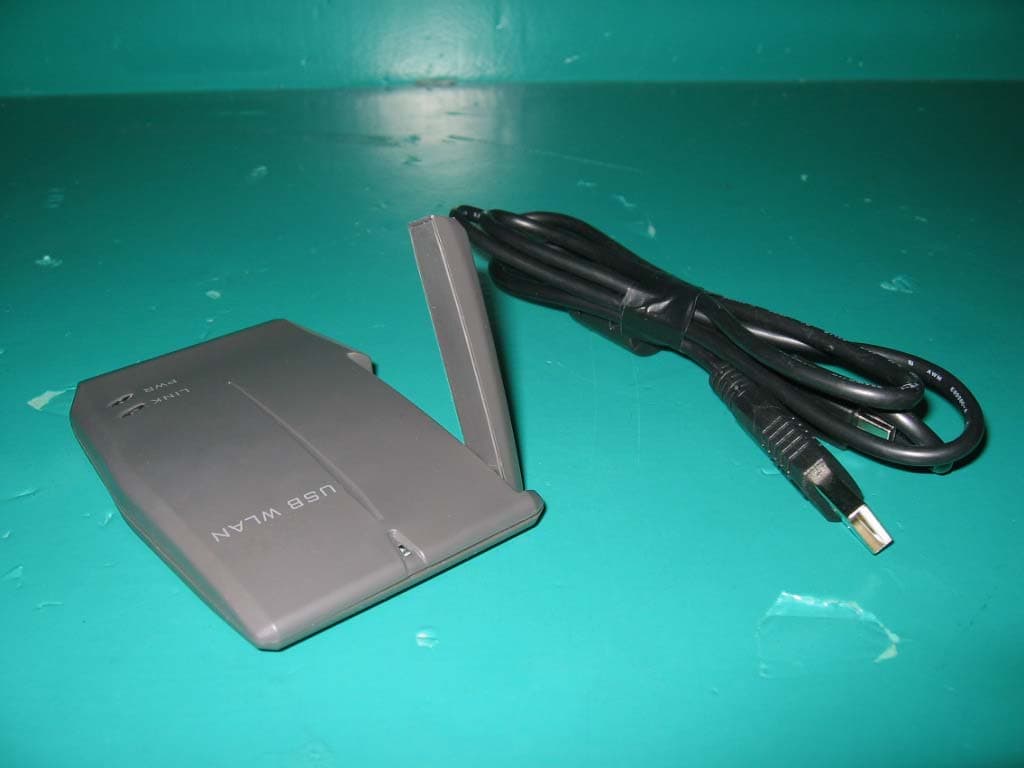
QP7802U1G1
Nov 10, 2004802.11G WLAN USB Adapter
Equipment Class
DTS - Digital Transmission System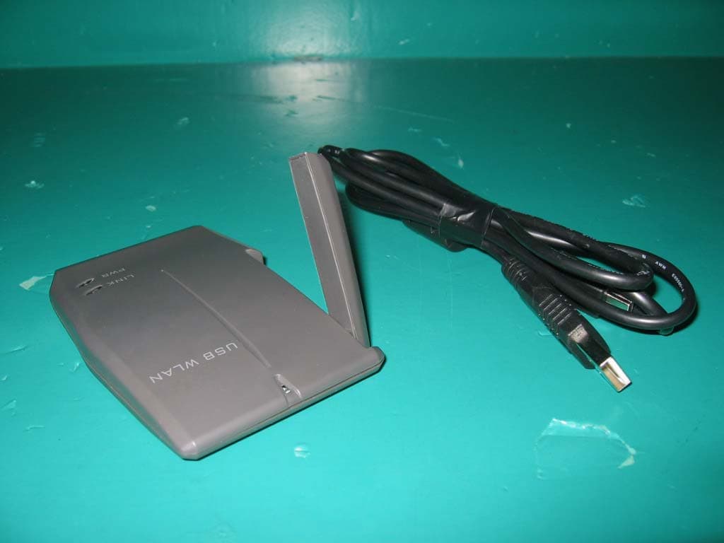
QP7802UIG1
Nov 10, 2004802.11g WLAN USB Adapter
Equipment Class
DTS - Digital Transmission System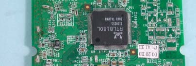
QP7-802MR
Jul 20, 2003Mini PCI 802.11b Wireless LAN Card
Equipment Class
DTS - Digital Transmission System
QP7-802MABB
Mar 05, 2003Wireless LAN 802.11a/b Dual Band Mini PCI Adapter
Equipment Class
DTS - Digital Transmission System
QP7-802MI3B
Dec 20, 2002802.11b Wireless LAN Mini-PCI Adapter
Equipment Class
DTS - Digital Transmission System