QP8-MEI915WLANRemote Data Port
Crane Payment Innovations
Click to zoom
Application Details
- Equipment Class
- DSS - Part 15 Spread Spectrum Transmitter
- Date of Grant
- Sep 29, 2003
- Application Purpose
- Original Equipment
- Date of Application
- Sep 28, 2003
- Equipment Note
- Remote Data Port
- Frequency Range
- 902.40000000 - 927.75000000
- Company
- Crane Payment Innovations
- Country
- United States
Documents & Files
Document Text
Text extracted from the exhibit documents filed with the FCC. Open a document above to read the original.
Users Manual
Technical Support 1-800-345-8172 Remote Data Port Page-1 www.meieasitrax.com Revision G1 Mars Inc. 2003 Printed in USA. MEI is a trademark of Mars, Inc. Information is subject to change without notice. MEI has made every effort to ensure that the information in this document is accurate. However, we cannot be held responsible for any errors or omissions. Remote Data Port Install Guide 1301 Wilson Drive West Chester PA 19380 www.meieasitrax.com Model: Part No.: Serial No.: Voltage: 24-34VDC, 0.5AMPS Technical Support 1-800-345-8172 Remote Data Port Page-2 www.meieasitrax.com Revision G1 TABLE OF CONTENTS INTRODUCTION General Information .............................................................................................. 3 Product Features.................................................................................................... 3 Interfaces Supported ............................................................................................. 3 PRODUCT OVERVIEW Serial Number......................................................................................................... 4 Configuration.......................................................................................................... 4 Configurable Remote Data Port .......................................................................... 4 MEI Easitrax VT1000........................................................................................... 5 MEI Easitrax Data Pod 200 ................................................................................. 5 Instruction Before Installation............................................................................. 5 Recommended Tools/Supplies.............................................................................. 5 Required Installation Standard ............................................................................ 5 AUTOMATIC PRODUCT INSTALLATION AP6000/7000 Series Snack Machine...............................................................6-8 DIXIE NARCO PRODUCT INSTALLATION Dixie Single Price Machine.............................................................................. 9-11 Dixie Narco Motor Cable Chart ........................................................................ 12 RMI PRODUCT INSTALLATION RMI 2000 / 8050 Machine ............................................................................ 13-15 Technical Support 1-800-345-8172 Remote Data Port Page-3 www.meieasitrax.com Revision G1 INTRODUCTION GENERAL INFORMATION The remote data port lets you add industry-standard DEX data transfer capabilities to machines that are not audit enabled or add enhanced capabilities to DEX-enabled machines. The remote data port gathers data on cash transactions and vending cycles, including coin drops, bill insertions and product sales. This information is stored for later collection. The remote data port is compatible with most vending machines and is simple to use and install. This manual is designed to assist in the installation of the remote data port into various vending machines. This manual will be revised periodically to ensure technical accuracy as more machines become available for retrofitting. The system is available in two options: 1.Cash Only - Monitors cash sales only. 2.Full Option- Monitors cash sales and product vends. PRODUCT FEATURES •Optional Mounting Bracket •Linear Motor Monitoring •Matrix Motor Monitoring •Status LED •DEX Jack Nominal Voltage: 24-34VDC INTERFACES SUPPORTED •Micromech Interface •Pulse & Serial Bill Validator •ACD (Accumulated Credit Display) •Cash Counter 1301 Wilson Drive West Chester PA 19380 www.meieasitrax.com Model: Part No.: Serial No.: Voltage: 24-34VDC, 0.5AMPS Technical Support 1-800-345-8172 Remote Data Port Page-4 www.meieasitrax.com Revision G1 CONFIGURATION The remote data port will be shipped with factory default settings. Each remote data port will require machine specific configuration using an MEI Support Tool. See MEI Easitrax Remote Data Port Configuration manual for instructions. REMOTE DATA PORT The remote data port is the core of the audit retrieval system. It allows for easy retrieval of cash transactions and/or product vending cycles. The remote data port has five connection points for interfacing the port directly or indirectly through data pods to the vending machine. PRODUCT OVERVIEW SERIAL NUMBER CONFIGURATION WWYLCCPPPPP WW- Week Manufactured (01 through 52) Y- Year Manufactured (2 for 2002) L- Manufacturing Location CC- Configuration Code PPPPP- Sequential Production Number P1 - 215630001 P2 - 215634004 P3 - 215638002 P4 - 215636003 P5 - 215632005 DDCMP/Printer Electronic Lock Config I/O, Dalla 1 Wire Temp LMM/MMM/DLMM/DMMM VMC Printer DEX Credit Card Reader RS485 LAN HII2 Interface One Wire Interface MDB Executive Interface (Master) Optional Battery- Rechargeable Micromech Coin Mech Executive Interface (Slave) Fill Sw. Detector (Req. External I/F) Printer Light Detector (Req. External Isolation) ACD Cash Counter I/F (Req. Isolation) Parallel Coin Mech Bill Validator Bottom View Technical Support 1-800-345-8172 Remote Data Port Page-5 www.meieasitrax.com Revision G1 MEI EASITRAX VT 1000 (LMM) The MEI EASITRAX VT 1000 is used when monitoring product vend cycles. It allows for high voltage monitoring of linear vend motors, credit line and cash counter. PRODUCT OVERVIEW MEI EASITRAX DATA POD 200 (DMMM) The MEI EASITRAX data pod 200 is used when monitoring product vend cycles. Its voltage source is the data port. It allows for 5V logic to monitor matrix vend motors. Before Installation ̈Verify that the machine and its components work properly prior to data port installation. ̈Power MUST be removed from the vendor prior to starting the installation. ̈Visually inspect machine cables for defects. Adjust/Replace as needed. ̈Perform a test vend and verify change payback. ̈Locate a position where the data port is easily accessible, make sure that harnesses will reach pod(s) and t…
Text truncated - open the document above for the full version.
Users Manual
Technical Support 1-800-345-8172 Remote Data Port Page-1 www.meieasitrax.com Revision G1 Mars Inc. 2003 Printed in USA. MEI is a trademark of Mars, Inc. Information is subject to change without notice. MEI has made every effort to ensure that the information in this document is accurate. However, we cannot be held responsible for any errors or omissions. Remote Data Port Install Guide 1301 Wilson Drive West Chester PA 19380 www.meieasitrax.com Model: Part No.: Serial No.: Voltage: 24-34VDC, 0.5AMPS Technical Support 1-800-345-8172 Remote Data Port Page-2 www.meieasitrax.com Revision G1 TABLE OF CONTENTS INTRODUCTION General Information .............................................................................................. 3 Product Features.................................................................................................... 3 Interfaces Supported ............................................................................................. 3 PRODUCT OVERVIEW Serial Number......................................................................................................... 4 Configuration.......................................................................................................... 4 Configurable Remote Data Port .......................................................................... 4 MEI Easitrax VT1000........................................................................................... 5 MEI Easitrax Data Pod 200 ................................................................................. 5 Instruction Before Installation............................................................................. 5 Recommended Tools/Supplies.............................................................................. 5 Required Installation Standard ............................................................................ 5 AUTOMATIC PRODUCT INSTALLATION AP6000/7000 Series Snack Machine...............................................................6-8 DIXIE NARCO PRODUCT INSTALLATION Dixie Single Price Machine.............................................................................. 9-11 Dixie Narco Motor Cable Chart ........................................................................ 12 RMI PRODUCT INSTALLATION RMI 2000 / 8050 Machine ............................................................................ 13-15 Technical Support 1-800-345-8172 Remote Data Port Page-3 www.meieasitrax.com Revision G1 INTRODUCTION GENERAL INFORMATION The remote data port lets you add industry-standard DEX data transfer capabilities to machines that are not audit enabled or add enhanced capabilities to DEX-enabled machines. The remote data port gathers data on cash transactions and vending cycles, including coin drops, bill insertions and product sales. This information is stored for later collection. The remote data port is compatible with most vending machines and is simple to use and install. This manual is designed to assist in the installation of the remote data port into various vending machines. This manual will be revised periodically to ensure technical accuracy as more machines become available for retrofitting. The system is available in two options: 1.Cash Only - Monitors cash sales only. 2.Full Option- Monitors cash sales and product vends. PRODUCT FEATURES •Optional Mounting Bracket •Linear Motor Monitoring •Matrix Motor Monitoring •Status LED •DEX Jack Nominal Voltage: 24-34VDC INTERFACES SUPPORTED •Micromech Interface •Pulse & Serial Bill Validator •ACD (Accumulated Credit Display) •Cash Counter 1301 Wilson Drive West Chester PA 19380 www.meieasitrax.com Model: Part No.: Serial No.: Voltage: 24-34VDC, 0.5AMPS Technical Support 1-800-345-8172 Remote Data Port Page-4 www.meieasitrax.com Revision G1 CONFIGURATION The remote data port will be shipped with factory default settings. Each remote data port will require machine specific configuration using an MEI Support Tool. See MEI Easitrax Remote Data Port Configuration manual for instructions. REMOTE DATA PORT The remote data port is the core of the audit retrieval system. It allows for easy retrieval of cash transactions and/or product vending cycles. The remote data port has five connection points for interfacing the port directly or indirectly through data pods to the vending machine. PRODUCT OVERVIEW SERIAL NUMBER CONFIGURATION WWYLCCPPPPP WW- Week Manufactured (01 through 52) Y- Year Manufactured (2 for 2002) L- Manufacturing Location CC- Configuration Code PPPPP- Sequential Production Number P1 - 215630001 P2 - 215634004 P3 - 215638002 P4 - 215636003 P5 - 215632005 DDCMP/Printer Electronic Lock Config I/O, Dalla 1 Wire Temp LMM/MMM/DLMM/DMMM VMC Printer DEX Credit Card Reader RS485 LAN HII2 Interface One Wire Interface MDB Executive Interface (Master) Optional Battery- Rechargeable Micromech Coin Mech Executive Interface (Slave) Fill Sw. Detector (Req. External I/F) Printer Light Detector (Req. External Isolation) ACD Cash Counter I/F (Req. Isolation) Parallel Coin Mech Bill Validator Bottom View Technical Support 1-800-345-8172 Remote Data Port Page-5 www.meieasitrax.com Revision G1 MEI EASITRAX VT 1000 (LMM) The MEI EASITRAX VT 1000 is used when monitoring product vend cycles. It allows for high voltage monitoring of linear vend motors, credit line and cash counter. PRODUCT OVERVIEW MEI EASITRAX DATA POD 200 (DMMM) The MEI EASITRAX data pod 200 is used when monitoring product vend cycles. Its voltage source is the data port. It allows for 5V logic to monitor matrix vend motors. Before Installation ̈Verify that the machine and its components work properly prior to data port installation. ̈Power MUST be removed from the vendor prior to starting the installation. ̈Visually inspect machine cables for defects. Adjust/Replace as needed. ̈Perform a test vend and verify change payback. ̈Locate a position where the data port is easily accessible, make sure that harnesses will reach pod(s) and t…
Text truncated - open the document above for the full version.
Cover Letter(s)
Date: 14 July 2003 To: American Telecommunications Certified Body 6731 Whittier Avnue Suite C110 McLean, Virginia 22101 From: MEI 1301 Wilson Drive West Chester, Pa. 19380 Subject: Certification Application - Request for Confidentiality FCC ID: QP8- MEI915WLAN Please be advised that the following information is to be held confidential on behalf of MEI.. • Schematics • Block Diagrams • Theory of Operation The application contains technical information which MEI deems to be trade secrets and proprietary. If made public, the information might be used to the disadvantage of the applicant in the market place. Thank you for your attention in this mater. Robert M.Carney Product Compliance Manager Tel: 610-430-2697 Fax: 601-430-2795 e-mail: [email protected] U:/Pro2002US Letter Request for Confidentiality.doc 1301 Wilson Drive, West Chester, Pennsylvania 19380-5963 Tel: (610) 430-2500 · Fax: (610) 430-2694 www.meiglobal.com
Cover Letter(s)
Date: 11 July 2003 To: American Telecommunications Certified Body 6731 Whittier Avnue Suite C110 McLean, Virginia 22101 From: MEI 1301 Wilson Drive West Chester, Pa. 19380 Subject: Letter of Agency To Whom it may concern, Please be advised that MEI authorizes Washington Laboratories, Ltd. to act on our behalf, until otherwise notified, for applications submitted to American Telecommunications Certified Body, Inc. (ATCB) We certify that we are not subject to denial of federal benefits, that includes FCC benefits, pursuant to Section 53011 of the Anti-Drug Abuse ACT of 1988, U.S.C. 862. Further, no party, as defined in 47 CFR 1.2002(b), to the application is subject to denial of federal benefits, that includes FCC benefits. Thanks you for your attention to this matter. Robert M.Carney Product Compliance Manager Tel: 610-430-2697 Fax: 601-430-2795 e-mail: [email protected] U:/Pro2002/US Letter of Agency_2.doc 1301 Wilson Drive, West Chester, Pennsylvania 19380-5963 Tel: (610) 430-2500 · Fax: (610) 430-2694 www.meiglobal.com
Cover Letter(s)
American Telecommunications Certification Body Inc. 6731 Whittier Ave, McLean, VA 22101 September 4, 2003 RE: FCC ID: QP8-MEI915WLAN Attention: Gregory M. Snyder / Brian J. Dettling I have a few comments on this Application. 1. Please complete the 731 form. The power level for the transmitter has not been filled in. - 2. Is this a simple FSK transmitter, or a Frequency Hopping Spread Spectrum device? The block diagram does not appear to be that of a typical FHSS device (i.e. FSK modulation is not in itself a FHSS modulation). Please explain. Please provide information on the chip rate for this device. - 3. Please note that the Frequency Hopping chart indicates that hopping may not pseudorandom as required but sequential in nature. (please note - 0, 10, 20, 30, 40, 50, 60, 70, 80, 90, etc appear to be sequential hop characterizations - which is not allowed.). Please explain how this is a pseudorandom hopping sequence meeting the requirements of a spread spectrum device under 15.247. - 4. Please note that the recorded power level of this device is 1 Watt. This is rather close to the limit. Consequently power measurements using an analyzer (while allowed by the FCC) may not be adequate to report the actual power of the device. This is especially true when the trace shows readings at or very near the top graticule. Measurements under this condition (even with external attenuation) may actually be that of a compressed signal. What measures have been taken in measuring power to verify that the signal is not being compressed (i.e. inserting another 10dB pad in line to make sure that an exact 10dB reduction in signal occurs would be one indicator that the measurement is valid). Please provide evidence that this signal is not compressed. - 5. Please note that when using an analyzer for peak power measurements, a resolution bandwidth correction factor must be used. This factor takes into account the measured 6dB bandwidth of the plot and the actual res bandwidth of the analyzer. Please note that in the conducted power plot the span is 20MHz. Thus each graticule is 2MHz wide. The 6dB bandwidth on this plot then would be approximately 3MHz. The resolution bandwidth correction factor would then be 10log(6dB BW/ actual Res BW or 1.7dB correction factor. This potentially puts the peak power over the 30dBm limit. Please verify the conducted output power is 30dBm or less by including any required resolution bandwidth correction factor or by measuring the peak power using a diode detector or peak power meter. - 6. Please note that you state the occupied bandwidth of this device is approximately 84kHz. Please note that it is unlikely that this meets the definition of a spread spectrum device. - 7. Please provide evidence that the receiver for this device meets the input bandwidth requirements for a spread spectrum receiver. - 8. Please note that on pages 34 to 36 of the report you have apparently mixed the uv/m and dBuv/m numbers in the limit column. Please explain and/or correct the column to be consistent. - Dennis Ward mailto:[email protected] The items indicated above must be submitted before processing can continue on the above referenced application. Failure to provide the requested information may result in application termination. Correspondence should be considered part of the permanent submission and may be viewed from the Internet after a Grant of Equipment Authorization is issued. Please do not respond to this correspondence using the email reply button. In order for your response to be processed expeditiously, you must submit your documents through the AmericanTCB.com website. Also, please note that partial responses increase processing time and should not be submitted. z Page 2 September 4, 2003 Any questions about the content of this correspondence should be directed to the sender.
Cover Letter(s)
dward From: Brian Dettling [[email protected]] Sent: Monday, September 29, 2003 12:45 PM To: 'ATCB- Dennis Ward' Cc: [email protected] Subject: FW: FW: QP8-MEI915WLAN COMMENTS 9/29/2003 Hello Dennis, Below is the response we received from our client representative. His inputs are in RED. He has included his contact info if you should need any additional info or clarification. Thanks! Brian -----Original Message----- From: [email protected] [mailto:[email protected]] Sent: Monday, September 29, 2003 2:09 PM To: [email protected] Subject: Re: FW: QP8-MEI915WLAN COMMENTS Hi Brian, Your answer to item 3 concerns me a little. Are you saying that the hop sequence originally provided was in error? If it was in error and the new hop sequence chart replaces a non-pseudorandom hopping sequence, then please confirm. If it does not replace an error, then it still concerns me that the hop sequence originally provided is anything but random and may be part of this system. Also, once the 50 channels have completed, does the device start over at the original start frequency or continue with the hop sequence - or in the case of a very short burst where the devices does not hop through all 50 channels, does the hopping sequence reset to the first channel the next transmission cycle? This is not allowed. The hop sequence table was re-ordered to "appear" more pseudo-random avoiding any misinterpretation. The hop sequence table meets the requirements of CFR 47, 15.247 (a)(1). The second half of this question is addressed below. I need to clarify the last question. In the instance of a short burst using less than the 50 channels the device must use the next frequency in the hop sequence - it cannot reset to the first channel used for the next transmission cycle. This is the concern with the last question. Sorry if I confused you with the way I asked the question. The channel sequence is tracked in software with a pointer. In the case of, "short burst" where all 50 channels are not used the pointer will stop at the last channel used. On the next transmission cycle the pointer will increment (Pointer + 1) to the next channel in the ordered list until all 50 channels are used. Only then will the pointer jump to the begining of the ordered list. If you need further clarification or a more indepth explanation, please call me immediately for a speedy resolution. ___________________________________________ Robert M. Carney MEI Sr. Design Assurance Engineer/Product Compliance Tel: (610)-430-2697 Fax: (610)-430-2795 E-mail: [email protected] I-net: http://www.meiglobal.com ___________________________________________ 9/29/2003
Cover Letter(s)
Response to ATCB Comments FCC ID: QP8-MEI915WLAN 1 Washington Laboratories, Ltd. 7560 LINDBERGH DRIVE GAITHERSBURG, MD 20879 (301) 417 – 0220 FAX # (301) 417 - 9069 September 19, 2003 Mr. Dennis Ward American Telecommunications Certification Body Inc. 6731 Whittier Ave McLean, VA 22101 RE: Comments of September 4, 2003 APPLICATION: QP8-MEI915WLAN Mars Electronics, Inc. Dear Mr. Ward: Below are the comments that you have provided regarding the application for certification referenced above. Our responses to those comments are in bold italic. Many responses refer you to additional exhibit(s) which has been uploaded to the application folder at the ATCB website. Thank you for your attention. Please feel free to contact us for any additional information that you may require. Regards, Gregory M. Snyder Chief EMC Engineer, Wireless/Telco Services Manager Brian J. Dettling Documentation Specialist WLL Project: 7008 1) Please complete the 731 form. The power level for the transmitter has not been filled in. R. Please see exhibit “EZ1 Form 731 Revised.pdf” that has been corrected to show the RF power. 2) Is this a simple FSK transmitter, or a Frequency Hopping Spread Spectrum device? The block diagram does not appear to be that of a typical FHSS device (i.e. FSK modulation is not in itself a FHSS modulation). Please explain. Please provide information on the chip rate for this device. R. The MEI wireless LAN (WLAN) is a frequency hopping spread spectrum transceiver in which the carrier is modulated in a conventional manner with FSK. This causes a conventional spreading of the Response to ATCB Comments FCC ID: QP8-MEI915WLAN 2 RF energy. The carrier is not fixed but hops to one of 50 channel frequencies selected from a preordered list of 5 independent groups of 50 channels. There are a total of 250 channels possibilities between 902MHz-928MHz but only one group of 50 channel frequencies is selected from the preordered list of 5 independent groups of 50 channels for system use. Channel hopping occurs between the channels in the selected set with a maximum on channel time of 0.4S within any 20 second period, which is limited by 47 CFR 15.247. The original block diagram did not indicate that the N register of the Phase Locked Loop (PLL) is programmable. This has been added to the block diagram to indicate that the N register is programmed from the controller DSP with the pseudorandom sequence generator. Since N determines the hop frequency it's then clear that frequency hopping is achieved by programming the N register in the PLL. Please see exhibit “EZ1 Block Diagram Revised.pdf.” 3) Please note that the Frequency Hopping chart indicates that hopping may not pseudorandom as required but sequential in nature. (please note - 0, 10, 20, 30, 40, 50, 60, 70, 80, 90, etc appear to be sequential hop characterizations - which is not allowed.). Please explain how this is a pseudorandom hopping sequence meeting the requirements of a spread spectrum device under 15.247. R. The current ordered list of hopping channels has been changed to make the hop appear pseudorandom in nature. The new list is provided in the exhibit “EZ1 Operational Description Revised.pdf.” 4) Please note that the recorded power level of this device is 1 Watt. This is rather close to the limit. Consequently power measurements using an analyzer (while allowed by the FCC) may not be adequate to report the actual power of the device. This is especially true when the trace shows readings at or very near the top graticule. Measurements under this condition (even with external attenuation) may actually be that of a compressed signal. What measures have been taken in measuring power to verify that the signal is not being compressed (i.e. inserting another 10dB pad in line to make sure that an exact 10dB reduction in signal occurs would be one indicator that the measurement is valid). Please provide evidence that this signal is not compressed. R. The power has been re-measured using a diode detector and power meter. Please refer to the exhibit “EZ1 Test Report Revision 1.pdf”. 5) Please note that when using an analyzer for peak power measurements, a resolution bandwidth correction factor must be used. This factor takes into account the measured 6dB bandwidth of the plot and the actual res bandwidth of the analyzer. Please note that in the conducted power plot the span is 20MHz. Thus each graticule is 2MHz wide. The 6dB bandwidth on this plot then would be approximately 3MHz. The resolution bandwidth correction factor would then be 10log(6dB BW/ actual Res BW or 1.7dB correction factor. This potentially puts the peak power over the 30dBm limit. Please verify the conducted output power is 30dBm or less by including any required resolution bandwidth correction factor or by measuring the peak power using a diode detector or peak power meter. R. The power has been re-measured using a diode detector and power meter. Please refer to the revised test report. 6) Please note that you state the occupied bandwidth of this device is approximately 84kHz. Please note that it is unlikely that this meets the definition of a spread spectrum device. Response to ATCB Comments FCC ID: QP8-MEI915WLAN 3 R. The MEI wireless LAN (WLAN) frequency hopping spread spectrum transceiver operates in the occupied bandwidth of 26 MHz, ie. 902Mhz to 928 Mhz spectrum space. The 84kHz referred to is referencing 20dB channel bandwidth. The requirement is for this bandwidth to be less than 250kHz. 7) Please provide evidence that the receiver for this device meets the input bandwidth requirements for a spread spectrum receiver. R. The 10.7MHz IF filter shown after the mixer (MURATA-SFECV10M7KA00-RO) has a 110KHz bandwidth which matches (with a small amount of excess) the hopping channel bandwidths of the transmitted signals (approximately 85KHz). The PLL is tuned to the correct frequency (10.7MHz + TX frequency) so that the received signal falls within the limits of this filter. Please …
Text truncated - open the document above for the full version.
External Photos
Top View Bottom Edge – Port View Right Side Left Side Top Edge Bottom View
Internal Photos
Cover Removed Boards in Place Main PCB With Radio Module Removed Bottom View of Main PCB Radio Module Top View (Shield Removed) Radio Module Bottom View
RF Exposure Info
Washington Laboratories, Ltd. 7560 LINDBERGH DRIVE GAITHERSBURG, MD 20879 (301) 417 – 0220 FAX # (301) 417 - 9069 Maximum Permissible Exposure Test Report for Mars Electronics, Inc. FCC ID: QP8-MEI915WLAN October 2, 2003 WLL PROJECT #: 7008RFFCC This report may not be reproduced, except in full, without the prior written consent of Washington Laboratories, Ltd. Mars Electronics, Inc. FCC ID: QP8-MEI915WLAN WLL Project #: 7008RFFCC 1 Maximum Permissible Exposure Test Report for Mars Electronics, Inc. QP8-MEI915WLAN 1.0 Introduction This report has been prepared on behalf of Mars Electronics, Inc. (MEI) to show compliance with the RF exposure requirements of FCC Part 15.247 as defined in FCC Part 1.1307(b)(1) for the MEI FHSS Transmitter. 3.8 Radio Frequency Radiation Exposure In accordance with Section 1.1310 of the FCC rules, the Maximum Permissible Exposure (MPE) limit for the frequency range of 902 to 928MHz is f/1500mW/cm 2 for General Population/Uncontrolled Access. The EUT is designed for use with vending machines for data transmissions and uses an antenna with a gain of 0dBi. A unique connector is used on the card to prevent the use of higher gain antennas. Warnings concerning RF exposure are in the installation manual. These warnings to the installers insure that the general public is not exposed to RF energy. The MEI FHSS Transmitter Module is designed for a transmit power of 29.35dBm (861mW). Using the intended antenna gain of 0dBi the following power density is calculated at a distance of 20cm. S = (PG)/(4πR 2 ) Where, S = Power Density (FCC Limit) = f/1500 = 928/1500 = 0.619 mW/cm 2 P = Output Power at the Antenna Terminals G = Gain of Transmit Antenna (linear gain) R = Distance from Transmitting Antenna For this device, the calculation is as follows: R = 20cm P = Output Power = 861mW G = Numeric Gain = 1 Solving for the power spectral density at 20cm. Mars Electronics, Inc. FCC ID: QP8-MEI915WLAN WLL Project #: 7008RFFCC 2 S = (PG) / (4πR 2 ) S = (861mW)(1) / (12.566)(20cm 2 ) = 0.171mW/cm 2 The calculated 0.171mW/cm 2 power density is under the FCC limit of 0.619mW/cm 2 at a distance of 20cm. Warnings are provided in the user’s manual to limit exposure to the direct beam during the installation and maintenance phase and to ensure that the antenna is installed at distances greater than 20cm cm from people. These warnings ensure that the device is installed properly and does not expose the general public to RF energy hazards.
Test Report
Document 7008-01, Rev. 1 FCC ID: QP8-MEI915WLAN FCC Certification Test Report Washington Laboratories, Ltd August 2003 FCC Certification Test Report for Mars Electronics, Inc. QP8-MEI915WLAN September 30, 2003 REVISION 2 issued September 30, 2003 Prepared for: Mars Electronics, Inc. 301 Wilson Drive Westchester, PA 19380 Prepared By: Washington Laboratories, Ltd. 7560 Lindbergh Drive Gaithersburg, Maryland 20879 FCC Certification Test Report Document 7008-01, Rev. 1 FCC ID: QP8-MEI915WLAN FCC Certification Test Report Washington Laboratories, Ltd August 2003 FCC Certification Test Program FCC Certification Test Report for the Mars Electronics, Inc. Easitrax Remote Data Port QP8-MEI915WLAN September 2, 2003 REVISION 1 issued September 19, 2003 WLL JOB# 7008 Prepared by: Brian J. Dettling Documentation Specialist …
Text truncated - open the document above for the full version.
Contact Information
Applicant
Robert M Carney(Global Compliance Manager)
Technical Contact
Washington Laboratories, Ltd.Gregory M Snyder
[email protected]301/ 417-0220
7560 Lindbergh Drive · Gaithersburg, Maryland · United States
Test Firm
Washington Laboratories, Ltd.Michael Violette
Technical Specifications
| # | Rule Parts | Frequency Range | Power Output |
|---|---|---|---|
| 1 | 15C | 902.4 MHz - 927.75 MHz | 861.00 mW |
Other Applications from Crane Payment Innovations
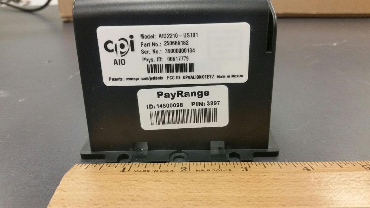
QP8ALIONOTEVZ
Jul 12, 2021ALIO Note is a cashless and telemetry system from CPI
Equipment Class
TNB - Licensed Non-Broadcast Station Transmitter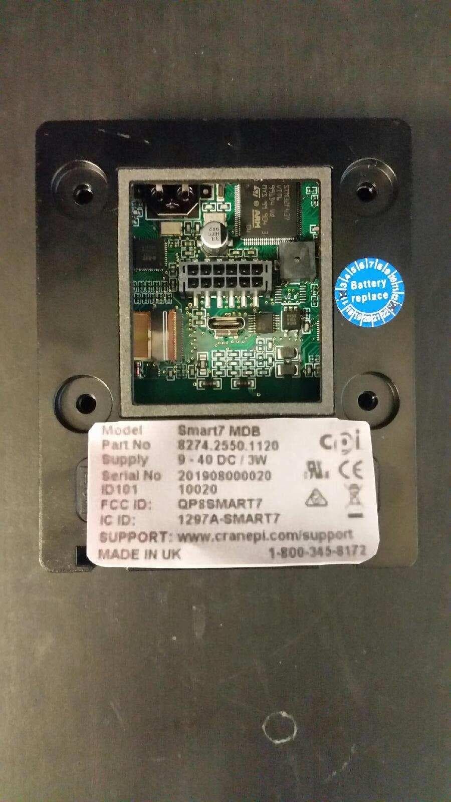
QP8SMART7
Jul 22, 2020SMART7 Card Reader Bezel
Equipment Class
DXX - Part 15 Low Power Communication Device Transmitter
QP8CORABTATT
Jun 11, 2020CORA modular data port
Equipment Class
PCB - PCS Licensed Transmitter
QP8ONETRACK
Jun 30, 2015RFID system
Equipment Class
DXX - Part 15 Low Power Communication Device Transmitter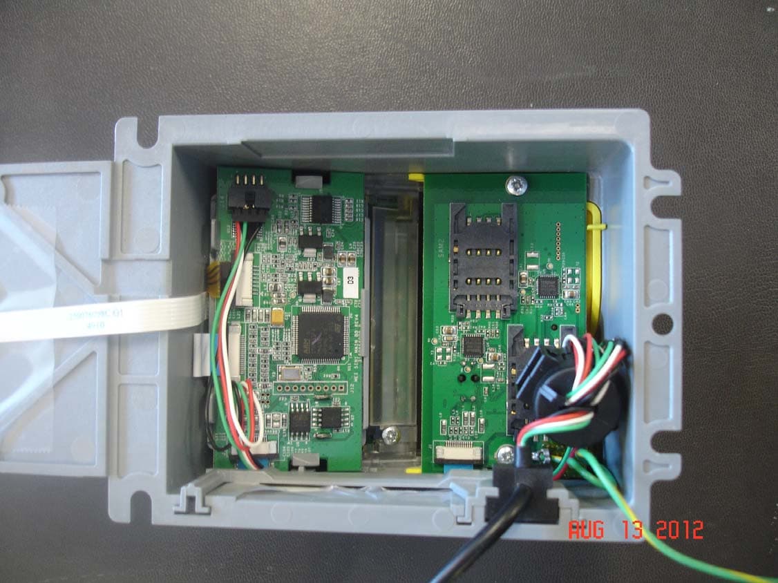
QP85IN1
Sep 04, 20125 in 1 Credit Card Bezel
Equipment Class
DXX - Part 15 Low Power Communication Device Transmitter