QP85IN15 in 1 Credit Card Bezel
Crane Payment Innovations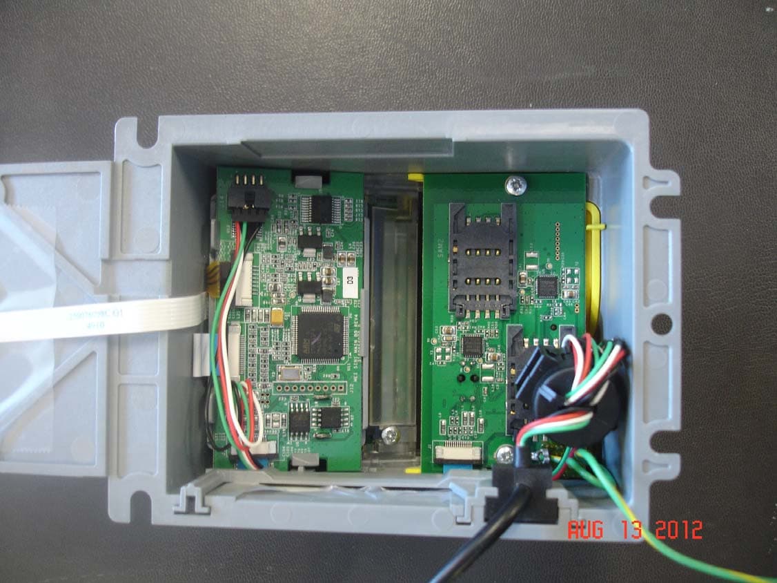
Click to zoom
Application Details
- Equipment Class
- DXX - Part 15 Low Power Communication Device Transmitter
- Date of Grant
- Sep 04, 2012
- Application Purpose
- Original Equipment
- Date of Application
- Sep 03, 2012
- Equipment Note
- 5 in 1 Credit Card Bezel
- Frequency Range
- 13.56000000 - 13.56000000
- Company
- Crane Payment Innovations
- Country
- United States
Documents & Files
Document Text
Text extracted from the exhibit documents filed with the FCC. Open a document above to read the original.
Users Manual
Bezel Cable Bezel Cable A A General Information The 5 in 1 bezel kit has been designed to add a credit card reader to a Series 2700 bill validator. The 5 in 1 bezel replaces the compact bezel. Remove the bill validator from the vending machine. To remove the compact bezel from the validator: 1. Remove four phillips screws (A) located on the front of the bezel. Slide the PCB cover ¼ inch towards the top of the validator and lift it off. Remove the old be zel and mounting plate. 5 in 1 bezel installation 2. Place the 5 in 1 bezel on the bill validator and tight en the three screws. Plug the ribbon cable (blue side up) into the lockin g socket on the validator control board. Be careful not to pinch or damage th e bezel cables when installing the 5 in 1 bezel. 3. Re-install the PCB cover. Remount the bill validator in the vending machine. 4. Plug the 5 in 1 bezel cable in to the Advance 5000 Bezel Socket. 5 in 1 Notes: FCC ID: QP85IN1 CANADA - IC: 1297A-MEI5IN1 CAUTION: changes or modifications not expressly approved by the party responsible for compliance could void the user’s authority to operate the equipment. This device complies with part 15 of the FCC rules. Operation is subject to the following two conditions: (a) This device may not cause harmful interference, and (b) this device must accept any interference received, including interfer ence that may cause undesired operation. Le présent appareil est conforme aux CNR d'I ndustrie Canada applicables aux appareils radio exempts de licence. L'exploitation est autorisée aux deux conditions suivantes : (1) l'appareil ne doit pas produire de brouillage, et (2) l'utilisateur de l'appareil doit accepter tout brouillage radioélectrique subi, même si le brouillage est susceptible d'en compromettre le fonctionnement. Contact MEI Technical Support @ 1-800-345-8172 with any questions. MEI 1301 Wilson Drive West Chester, Pa. 19380 ©2012 MEI Inc. Part # XXXXXXXXX www.meigroup.com General Information The 5 in 1 bezel kit has been designed to add a credit card reader to a Series 2700 bill validator. The 5 in 1 bezel replaces the compact bezel. Remove the bill validator from the vending machine. To remove the compact bezel from the validator: 1. Remove four phillips screws (A) located on the front of the bezel. Slide the PCB cover ¼ inch towards the top of the validator and lift it off. Remove the old bezel and mounting plate. 5 in 1 bezel installation 2. Place the 5 in 1 bezel on the bill validator and tighten the th ree screws. Plug the ribbon cable (blue side up) into the locking socket on the validator control board. Be careful not to pinch or damage th e bezel cables when installing the 5 in 1 bezel. 3. Re-install the PCB cover. Remount the bill validator in the vending machine. 4. Plug the 5 in 1 bezel cable in to the Advance 5000 Bezel Socket. 5 in 1 Notes: FCC ID: QP85IN1 CANADA - IC: 1297A-MEI5IN1 CAUTION: changes or modifications not expressly approved by the party responsible for compliance could void the user’s authority to operate the equipment. This device complies with part 15 of the FCC rules. Operation is subject to the following two conditions: (a) This device may not cause harmful interference, and (b) this device must accept any interference received, including interfer ence that may cause undesired operation. Le présent appareil est conforme aux CNR d'I ndustrie Canada applicables aux appareils radio exempts de licence. L'exploitation est autorisée aux deux conditions suivantes : (1) l'appareil ne doit pas produire de brouillage, et (2) l'utilisateur de l'appareil doit accepter tout brouillage radioélectrique subi, même si le brouillage est susceptible d'en compromettre le fonctionnement. Contact MEI Technical Support @ 1-800-345-8172 with any questions. MEI 1301 Wilson Drive West Chester, Pa. 19380 ©2012 MEI Inc. Part # XXXXXXXXX www.meigroup.com VN2700 series Bill Validator, 5 in 1 Bezel Kit Installation Guide VN2700 series Bill Validator, 5 in 1 Bezel Kit Installation Guide Locking collar Locking collar
External Photos
External Photos ©2008 Washington Laboratories, Ltd FCC ID: QP85IN1 and IC: 1297A-MEI5IN1 External Photos ©2008 Washington Laboratories, Ltd FCC ID: QP85IN1 and IC: 1297A-MEI5IN1 External Photos ©2008 Washington Laboratories, Ltd FCC ID: QP85IN1 and IC: 1297A-MEI5IN1 External Photos ©2008 Washington Laboratories, Ltd FCC ID: QP85IN1 and IC: 1297A-MEI5IN1 External Photos ©2008 Washington Laboratories, Ltd FCC ID: QP85IN1 and IC: 1297A-MEI5IN1 External Photos ©2008 Washington Laboratories, Ltd FCC ID: QP85IN1 and IC: 1297A-MEI5IN1
ID Label/Location Info
N OT S U B J E C T T O E C N C ON T R OL A D V A N C E D I N F OR M A T I ON D A T A M A Y C H A N GE W I T H OU T N OT I C E FINISH - 22/JUN/12 WCR - - - - BLANK LABEL P/N 250058354 000.000 IMPRINT SPEC, LABEL, 5IN1, 250058550 G1 4:1 1 S. NGUYEN D. DEAVILLE 22/JUN/12 22/JUN/12 CS A B C D E F G H 4321 4 3 21 H G F E D C B A - CHANGE HISTORY AFTER INITIAL RELEASE SEE MEI MRP DATABASE FOR IF IN DOUBT ASK INITIAL END PRODUCT: DO NOT MEASURE OFF THIS PRINT - - - - RETURNED TO MEI WHEN IT IS NO LONGER NEEDED. NOTICE OF CONFIDENTIALITY: TOOLING INFORMATION SHOULD ALWAYS BE KEPT IN A SECURE PLACE, AND SHOULD BE DESTROYED OR ASSET # MEI TOOL REF. RELEASED FOR: UNLESS OTHERWISE SPECIFIED : THIS DRAWING REPLACES: USA TITLE SIZEDESIGN CENTERDOC CLASSDWG NO.REV °DIMENSIONS ARE IN MILLIMETRES OR DEGREES °3RD ANGLE PROJECTION °LINEAR & ANGULAR TOLERANCES . THE DOCUMENT VENDORS 0.50 XX. 0.20 XX.X 0.10 XX.XX 0.05 °GEOMETRIC DIMENSIONS AND TOLERANCES PER ANSI Y14.5M-1994 AND ISO 8015 REFERENCE PART NO.: DRAWN: CHECKED: PROJECT ENGINEER: DATE DATE DATE SCALE: VOLUME: (CUBIC MM) SHEET 1 OF A FCC ID PLUS IC B. CARNEY -SEE NOTES SOURCE 1 SOURCE 2 GENERIC - - MATERIAL / FINISH - THIS DOCUMENT AND THE INFORMATION CONTAINED IN IT ARE CONFIDENTIAL AND ARE THE PROPERTY OF MEI. THEY MAY NOT BE IN ANY WAY DISCLOSED, COPIED OR USED BY ANYONE EXCEPT AS EXPRESSLY AUTHORIZED BY MEI XX.XXX SERIES 2000 - 5IN1 NOTE: LABEL TO BE PRINTED AS SHOWN AT MANUFACTURING LOCATION.1. PRINTING COLOR: BLACK.2. USE BLANK LABEL P/N 250058354.3. 4. SEE MEI SPECIFICATION 112659001 EXAMPLE NO. 2 FOR PREFERRED RUN DIRECTION. 5. SEE MEI SPECIFICATION 002584062 FOR COMPLIANCE REQUIREMENTS AND RESTRICTED MATERIALS AND RECYCLING NOTES. 6. SEE MEI SPECIFICATION 20001-002610104-SC FOR IMPRINT REQUIREMENTS. 65.0 30.0 Certification ‐ MEI 5 in 1 Credit Card Bezel FCC ID: QP85IN1 IC: 1297AMEI5IN1 Labeling – configurations 1) 5 in 1, Standalone: reference 47 CFR Part 15.19 (a) (3) When the MEI 5 in 1 credit card bezel is used standalone a metal back plate covers the back side of the bez el effectively blocking off access to the electronics from dirt or serviceman. The product label is placed on the outside of the back plate. The label contains the FCC ID & IC technical acceptance ID number as well as required FCC statement, model, part number, and serial number. The FCC ID, IC te chnical acceptance ID, required FCC statement (in English & French) are also placed into the installation guide. 2) 5 in 1, Mounted on the Series 2000 bill acceptor: reference 47 CFR Part 15.19 (a) (5) When MEI 5 in 1 credit card bezel is used with an MEI Series 2000 bill accepter the MEI 5 in 1 back plate is not used . The MEI 5 in 1 credit card bezel in then mechanically mounted to the front of a Series 2000 bill acceptor. The product label is placed on the inside, bottom, flat section of the bezel prior to moun ting so that it is always part of the product. The reason for this location is to preserve the label form the harsh external vending environment and to maintain the physical aesthetics externally of the MEI 5 in 1 credit card bezel. The FCC ID, IC technical acceptance ID, required FCC statement (i n English & French) are also placed into the installation guide. 3) The next page is meant to show the label location only. The artwork on page 1 of this exhibit will be used for the label. Label Location ©2007 Washington Laboratories, Ltd FCC ID:
Internal Photos
Internal Photos ©2008 Washington Laboratories, Ltd FCC ID: QP85IN1 & IC: 1297A-MEI5IN1 Internal Photos ©2008 Washington Laboratories, Ltd FCC ID: QP85IN1 & IC: 1297A-MEI5IN1 Internal Photos ©2008 Washington Laboratories, Ltd FCC ID: QP85IN1 & IC: 1297A-MEI5IN1 Internal Photos ©2008 Washington Laboratories, Ltd FCC ID: QP85IN1 & IC: 1297A-MEI5IN1 Internal Photos ©2008 Washington Laboratories, Ltd FCC ID: QP85IN1 & IC: 1297A-MEI5IN1
Test Report
Certificates and reports shall not be reproduced except in full, without the written permission of Washington Laboratories, Limited. FCC / Industry Canada Certification Test Report MEI MEI 5 IN 1 CREDIT CARD BEZEL WLL REPORT# 12589-01 Rev 0 July 31, 2012 Re-issued August 28, 2012 FCC ID: QP85IN1 IC ID: 1297A-MEI5IN1 Prepared for: MEI 1301 Wilson Drive West Chester, PA 19380 Prepared By: Washington Laboratories, Ltd. 7560 Lindbergh Drive Gaithersburg, Maryland 20879 Testing Certificate AT-1448 MEI MEI 5 in 1 Credit Card Bezel FCC Verification Test Report July, 2012 WLL Report #12589-01 Rev 0 - Page ii - © 2012 Washington Laboratories, Ltd. FCC / Industry Canada Certification Test Report For the MEI MEI 5 IN 1 CREDIT CARD BEZEL FCC ID: QP85IN1 IC ID: 1297A-MEI5IN1 WLL REPORT# 12589-01 Rev 1 July 31, 2012 Re-issued August 28, 2012 Prepared by: ___________________________ Steven Dovell Compliance Engineer Reviewed by: ____________________________ Michael F. Violette, P.E. President MEI MEI 5 in 1 Credit Card Bezel FCC Declaration of Conformity Test Report July, 2012 WLL Report #12589-01 Rev 0 - Page iii - © 2012 Washington Laboratories, Ltd. Abstract This report has been prepared on behalf of MEI to support the attached Application for Equipment Authorization. The test report and application are submitted for an Intentional Radiator under Part 15.225 of the FCC Rules and Regulations and Industry Canada RSS210. This Certification Test Report documents the test configuration and test results for a MEI 5 in 1 Credit Card Bezel. Testing was performed on an Open Area Test Site (OATS) of Washington Laboratories, Ltd, 7560 Lindbergh Drive, Gaithersburg, MD 20879. Site description and site attenuation data have been placed on file with the FCC's Sampling and Measurements Branch at the FCC laboratory in Columbia, MD. Washington Laboratories, Ltd. has been accepted by the FCC and approved by ACLASS under Certificate AT-1448 as an independent FCC test laboratory. These tests are accredited and meet the requirements of ISO/IEC 17025 as verified by the ANSI-ASQ National Accreditation Board/ACLASS. Refer to certificate and scope of accreditation AT-1448. The MEI 5 in 1 Credit Card Bezel complies with the limits for an Intentional Radiator device under FCC Part 15.225 and Industry Canada RSS 210. . Revision History Reason Date Rev 0 Initial Release July 31, 2012 Rev 1 Corrected limits & added maximum spurious emissions to table August 28, 2012 MEI MEI 5 in 1 Credit Card Bezel FCC Declaration of Conformity Test Report July, 2012 WLL Report #12589-01 Rev 0 - Page iv - © 2012 Washington Laboratories, Ltd. Table of Contents Abstract .................................................................................................................................................................... ii 1.1 Compliance Statement .............................................................................................................................. 1 1.2 Test Scope Summary ................................................................................................................................ 1 1.3 Contract Information ................................................................................................................................. 1 1.4 Test Dates ................................................................................................................................................. 1 1.5 Test and Support Personnel ...................................................................................................................... 1 1.6 Abbreviations ............................................................................................................................................ 2 2 Equipment Under Test ............................................................................................................................... 3 2.1 EUT Identification & Description ............................................................................................................ 3 2.2 Test Configuration .................................................................................................................................... 3 2.3 Testing Algorithm ..................................................................................................................................... 4 2.4 Measurements ........................................................................................................................................... 5 2.5 Test Location ............................................................................................................................................ 5 2.6 Measurement Uncertainty ......................................................................................................................... 6 3 Test Equipment ........................................................................................................................................... 7 4 Test Results .................................................................................................................................................. 8 4.1 Occupied Bandwidth ................................................................................................................................. 8 4.2 Radiated Spurious Emissions: FCC §15.225, §15.209, RSS 210 §A2.6, RSS GEN §7.2.5 ..................... 9 4.2 Conducted Emissions (AC Power Line) FCC §15.207, RSS GEN §7.2.4 ............................................. 14 4.3 Frequency Stability: FCC Part §2.1055, §15.225, RSS GEN §4.7, RSS 210 §A2.6 .............................. 16 List of Tables Table 1. Device Summary .....................................................................................................................................3 Table 2: Expanded Uncertainty List .....................................................................................................................…
Text truncated - open the document above for the full version.
Test Setup Photos
Test Setup Photos ©2008 Washington Laboratories, Ltd Test Setup Photos ©2008 Washington Laboratories, Ltd Test Setup Photos ©2008 Washington Laboratories, Ltd Test Setup Photos ©2008 Washington Laboratories, Ltd Test Setup Photos ©2008 Washington Laboratories, Ltd
Contact Information
Applicant
Robert M Carney(Global Compliance Manager)
Technical Contact
Washington Laboratories, Ltd.Steven D. Koster
[email protected]301-216-1500
7560 Lindbergh Drive · Gaithersburg, Maryland · United States
Test Firm
Washington Laboratories, Ltd.Steve Koster
Technical Specifications
| # | Rule Parts | Frequency Range | Power Output |
|---|---|---|---|
| 1 | 15C | 13.56 MHz - 13.56 MHz | - |
Other Applications from Crane Payment Innovations
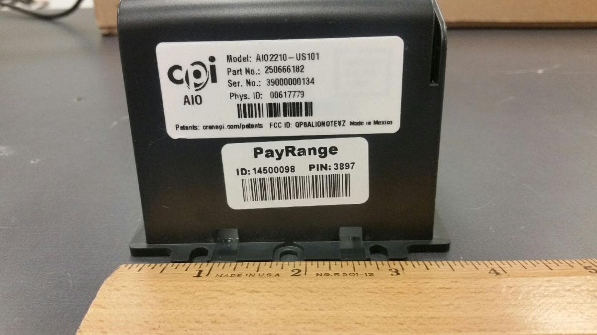
QP8ALIONOTEVZ
Jul 12, 2021ALIO Note is a cashless and telemetry system from CPI
Equipment Class
TNB - Licensed Non-Broadcast Station Transmitter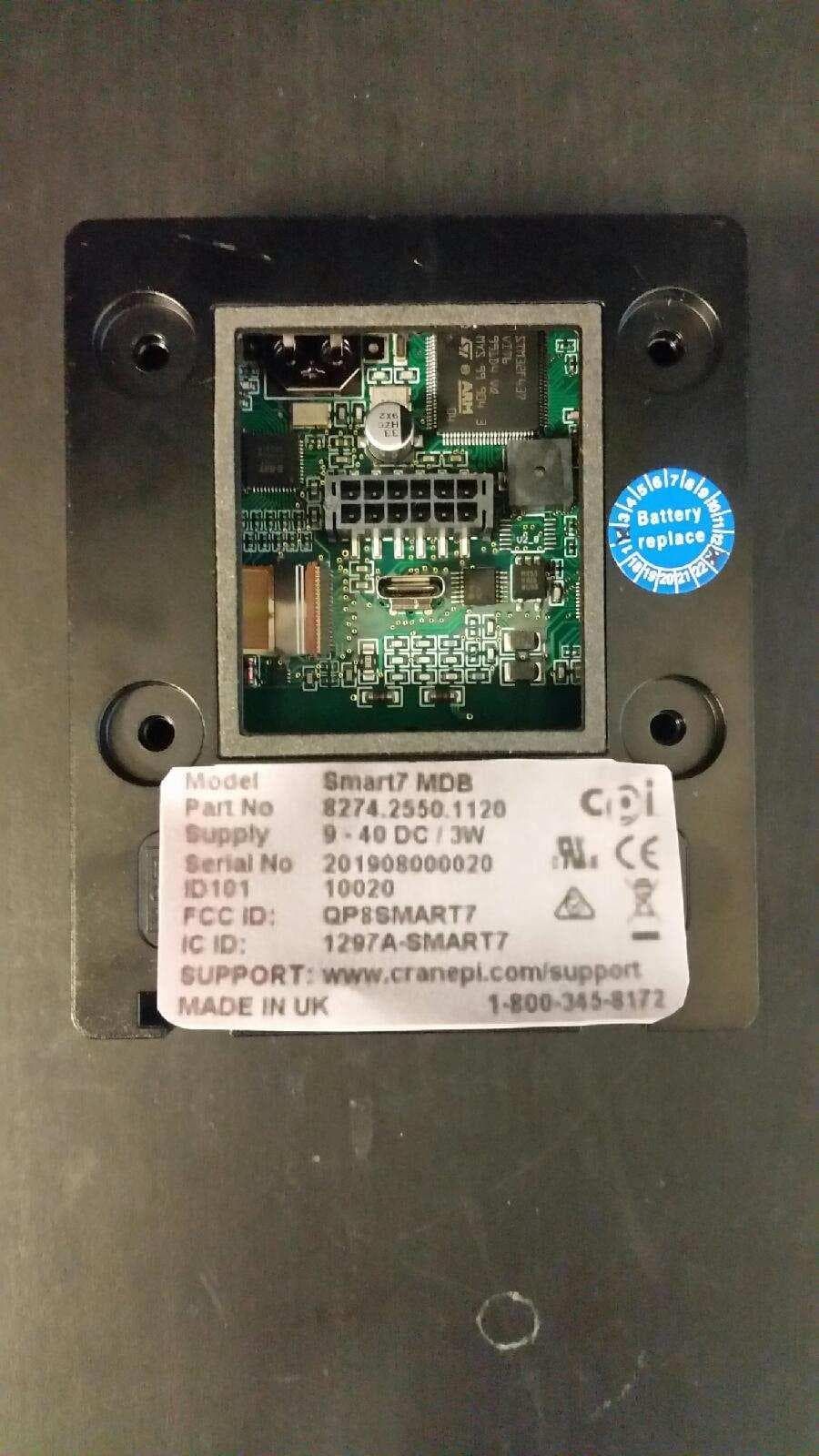
QP8SMART7
Jul 22, 2020SMART7 Card Reader Bezel
Equipment Class
DXX - Part 15 Low Power Communication Device Transmitter
QP8CORABTATT
Jun 11, 2020CORA modular data port
Equipment Class
PCB - PCS Licensed Transmitter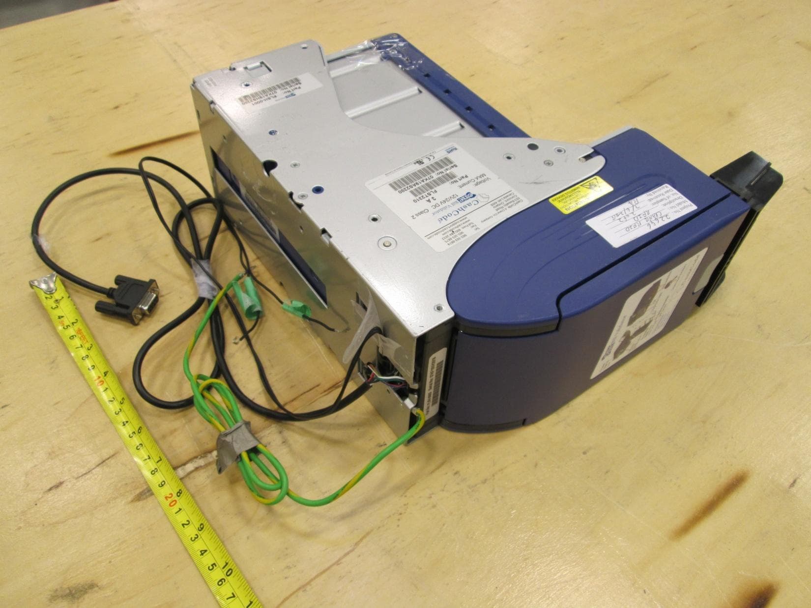
QP8ONETRACK
Jun 30, 2015RFID system
Equipment Class
DXX - Part 15 Low Power Communication Device Transmitter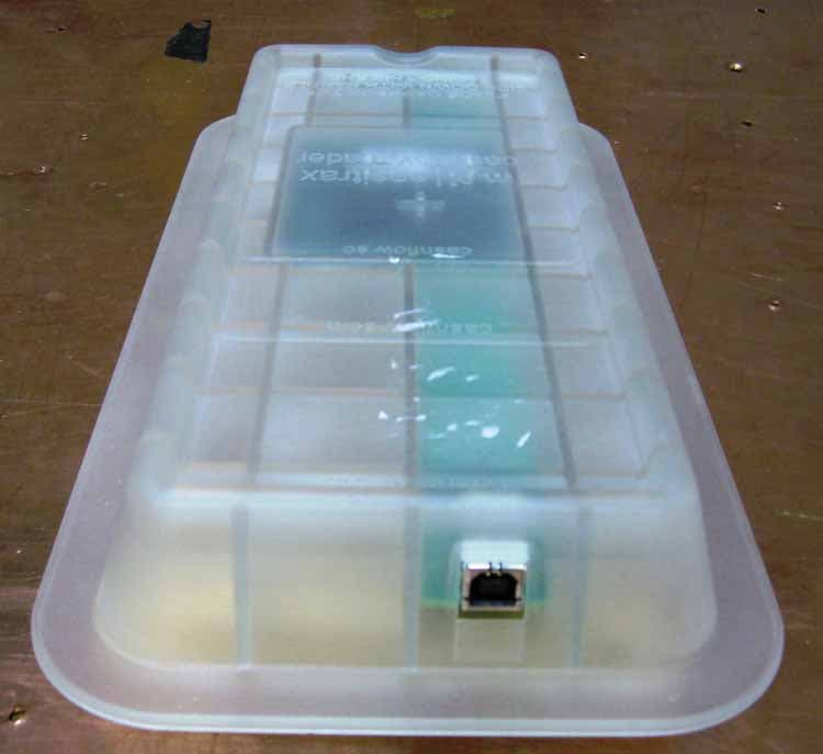
QP8EASITRAXRB
Oct 19, 2007RFID System
Equipment Class
DXT - Part 15 Low Power Transceiver, Rx Verified