QP8SMART7SMART7 Card Reader Bezel
Crane Payment Innovations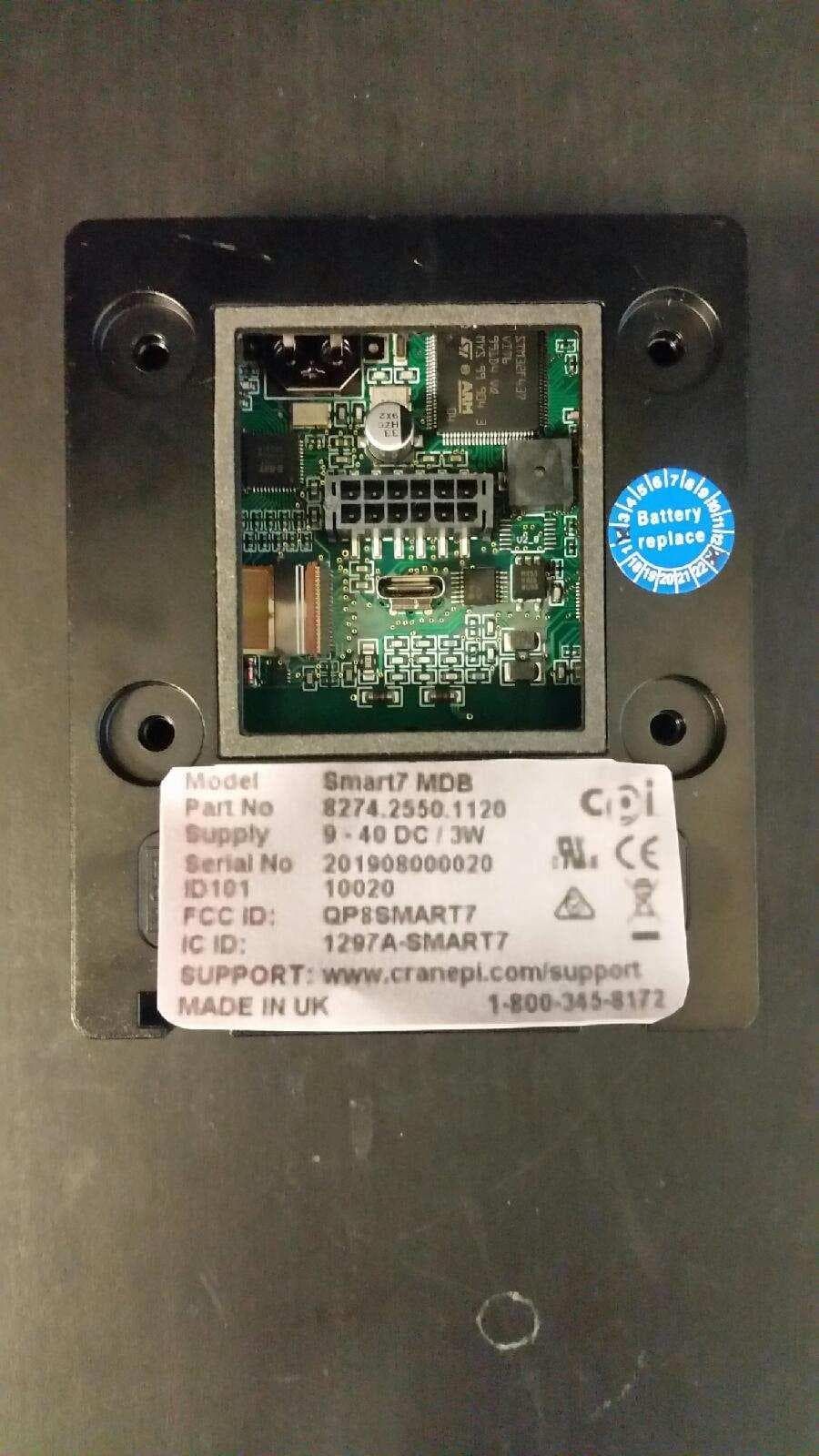
Click to zoom
Application Details
- Equipment Class
- DXX - Part 15 Low Power Communication Device Transmitter
- Date of Grant
- Jul 22, 2020
- Application Purpose
- Original Equipment
- Date of Application
- Jul 22, 2020
- Equipment Note
- SMART7 Card Reader Bezel
- Frequency Range
- 13.56000000 - 13.56000000
- Company
- Crane Payment Innovations
- Country
- United States
Documents & Files
Document Text
Text extracted from the exhibit documents filed with the FCC. Open a document above to read the original.
Users Manual
CPI G7 Smart 7 Install Guide G7 Smart 7 Install Guide EN v1.0.2.docx 1 / 13 01.04.2020 G7 Smart 7 Install Guide v.1.0.3 CPI G7 Smart 7 Install Guide G7 Smart 7 Install Guide EN v1.0.2.docx 2 / 13 01.04.2020 Author: Wolfgang Renner, 23 January 2020 Revised: W.Renner, 1 April 2020 Filename: G7 iSmart 7 Install Guide EN.docx Copyright: Crane Payment Innovations AG Nordringstrasse 16 CH-4702 Oensingen Tel: +41 62 388 45 45 Fax: +41 62 388 45 55 COPYRIGHT © 2020 Crane Payment Innovations The information contained herein is the Crane Payment Innovations. This copyright extends to all the media in which this information may be preserved including magnetic storage, punched card, paper tape, CDROM, computer printout or visual display. History Date: Modification 27.01.2020 First Draft version of document 04.02.2020 First internal version v1.0 of document 07.02.2020 Product name changed to “Smart 7” 01.04.2020 Added Mounting the device 28.05.2020 Added Compliance Section 7 CPI G7 Smart 7 Install Guide G7 Smart 7 Install Guide EN v1.0.2.docx 3 / 13 01.04.2020 Table of Contents 1 Introduction ...........................................................................................................................................4 2 Smart 7 Hardware .................................................................................................................................4 2.1 Smart 7 MDB .................................................................................................................................................................. 4 2.2 Smart 7 RS232 ................................................................................................................................................................ 4 3 Smart 7 Install and Configuration ..........................................................................................................5 3.1 Using the e-vending server ............................................................................................................................................ 5 3.1.1 Edit Configuration ................................................................................................................................................ 6 3.1.2 Generate Config. File ............................................................................................................................................ 6 3.1.3 Archive File Format .............................................................................................................................................. 7 3.2 Smart 7 Set Up and Configuration Summary ................................................................................................................. 7 3.2.1 Set up configuration ............................................................................................................................................. 7 3.2.2 Generate Config. File ............................................................................................................................................ 7 3.2.3 Download Copy Config. File from PC to the reader .............................................................................................. 7 3.2.4 Download Config. File via USB Stick to the reader ............................................................................................... 7 4 Smart 7 Status and Display Messages ...................................................................................................9 4.1 Display Messages ........................................................................................................................................................... 9 4.2 Status LED ...................................................................................................................................................................... 9 5 Support Packages ............................................................................................................................... 10 5.1 Config ........................................................................................................................................................................... 10 5.2 Logs .............................................................................................................................................................................. 11 5.3 Protocols ...................................................................................................................................................................... 11 5.4 Selections ..................................................................................................................................................................... 11 5.5 Statistics ....................................................................................................................................................................... 12 5.6 Taglist ........................................................................................................................................................................... 12 6 Attaching the device ........................................................................................................................... 13 7 Compliance...........................................................................................................................................13 CPI G7 Smart 7 Install Guide G7 Smart 7 Install Guide EN v1.0.2.docx 4 / 13 01.04.2020 1 Introduction This document describes the CPI Generation 7 iSmart Readers Firmware- and Configuration install and set up procedures. It considers the basic differences between the previous reader generations in terms of set up, operating and testing procedures. 2 Smart 7 Hardware The Smart 7 comes in two different Type Models, the Smart 7 MDB and the Smart 7 RS232. Each of them are available in two versions, with display and without display. 2.1 S…
Text truncated - open the document above for the full version.
Block Diagram
Filter Amplifier Matching Antenna 50 Ohm 13.56 MHz Tx1 Tx2 RFID Tranceiver TVSS RXN FCC ID:QP8SMART7 RFID Block diagram 27,12MHz U 1_6 Q 1_6 RXP Filter
Cover Letter(s)
CPI Crane Payment Innovations 3222 Phoenixville Pike ● Suite 200 ● Malvern ● PA 19355 Tel: +1 610 430 2700 ● Fax: +1 610 918 8898 Date: June 1, 2020 American Certification Body, Inc. 6731 Whittier Avenue Suite C110 McLean, VA 22101 To Whom It May Concern: ______Washington Laboratories Ltd.______ is authorized to act on our behalf, until otherwise notified, for applications to American Certification Body, Inc. (ACB). We certify that we are not subject to denial of federal benefits, that includes FCC benefits, pursuant to Section 5301 of the Anti-Drug Abuse Act of 1988, 21 U.S.C. 862. Further, no party, as defined in 47 CFR 1.2002 (b), to the application is subject to denial of federal benefits, that includes FCC benefits. We also declare that the information provided to the FCC is true and correct to the best of our knowledge (47 CFR 2.911(d)) and we have been informed of the grantee responsibilities (47 CFR 2.909) with regard to certified equipment. Thank you, Agency Agreement Expiration Date: (Typically 8-12 months) By: __________________________ Robert M Carney (Signature) (Print name) Title: Product Safety & Compliance Engineering Manager On behalf of: Crane Payment Innovations Inc. (Company Name) Telephone: +1 (610) 430 2700, Ext# 2697 Robert M Carney
External Photos
Crane Payment Innovations, Inc FCC ID: QP8SMART7, IC:1297A-SMART7 External Photos: “No Display” Front: No Display Back: No Display, FCC / IC Label Crane Payment Innovations, Inc FCC ID: QP8SMART7, IC:1297A-SMART7 “With Display” Front: with Display Back: with Display, FCC / IC Label
Internal Photos
Crane Payment Innovations, Inc FCC ID: QP8SMART7 , IC: 1297A-SMART7 Internal Pictures SMART7 “No Display” Back Side: 2-125-03-05b Front Side: 2-125-03-05b Crane Payment Innovations, Inc FCC ID: QP8SMART7 , IC: 1297A-SMART7 “With Display” Back Side: 2-125-03-05a Front Side: 2-125-03-05a
Operational Description
The NFC (RFID) driver PN5180 from NXP is used in the SMART7 reader The NFC frontend IC from NXP operates on a carrier frequency of 13.56MHz and transmits contactless energy and data. This frontend IC uses a modulation and demodulation concept that is fully integrated for various types of contactless communication methods and protocols. Th e PN518 0 fronte nd IC suppor ts the followin g RF operati ng modes: • Reader/Writer mode supporting ISO/IEC 14443 type A up to 848 kBit/s • Reader/Writer communication mode for MIFARE Classic contactless IC • Reader/Writer mode supporting ISO/IEC 14443 type B up to 848 kBit/s • Reader/Writer mode supporting JIS X 6319-4 (comparable with FeliCa scheme) • Supports reading of all NFC tag types (type 1, type 2, type 3, type 4A and type 4B) • Reader/Writer mode supporting ISO/IEC 15693 • Reader/Writer mode supporting ISO/IEC 18000-3 Mode 3 • ISO/IEC 18092 (NFC-IP1) • ISO/IEC 21481 (NFC-IP-2) Functionality of the NFC frontend type PN5180 from NXP Magnetic coupling between reader (PCD) and card (PICC) Block diagram of PN5180 NFC frontend Block diagram of the SMART7 antenna design Oensingen, 2 June 2020/DN Calculations of the SMART7 antenna gain INPUTS Efficiency in % (η) = 10% Physical Aperture Area in meters 2 (A) = 0.0016m 2 Wave Length (λ) = 22.123894 [Frequency 13.56MHz] OUTPUT Formula G dBi = 10 LOG 10 (η 4 πA / λ 2 ) Antenna Gain = -34dBi Blue EMC Output Filter Frequency = 15.5MHz Braun Antenna Adaptation Impedance = 250 ohm Green Antenna Design Inductivity = 1.085uH Quality Factor = 25 (Card) (SMART7) The SMART7 polls for a card (tag) in its field twice a second with a duty cycle of 400mS/on - 100mS/off. Once a card is encountered the carrier turns on 100% energizing the card and data is sent to the SMART7 from the card in support of cashless transaction.
Schematics
11 22 33 44 D D C C B B A A MICROTRONICDünnernstrasse 324702 OensingenSchweiz C:\AltiumDesigner\PRJ_AltiumDesigner14.x.x\_____Rea ders Generation 7\___iSmart7\iSmart7_Microcontrolle r_Revision5.SchDoc Sheet Name : Size : Sheet Number :File : Revision :Sheet of A4 [email protected] eMail :Web : Modified Date : ++41 (0)62 388 45 45++41 (0)62 388 45 55 Fon :Fax : MICROTRONIC MICROTRONICMICROTRONICMICROTRONIC 9 1 5 2-125-03-XXx Drawn By : DN Project : iSmart729.04.2020 electronic systems Microcontroller eMMC_D3eMMC_CMDeMMC_D0eMMC_CLKeMMC_D1eMMC_D2 33E R8_1 33E R7_1 33E R3_1 33E R2_1 33E R1_1 RESET_LOW GND +3,3V 100K R18_1 100KR19_1 100KR20_1 GND +3,3V 1 2 CR1220 (3VDC) B1_1 32,768KHz Q2_1 27pF/50V 2% C1_1 27pF/50V 2% C2_1 4,3pF/50V 0,25 C3_1 4,3pF/50V 0,25 C4_1 100nF/16VC5_1 100nF/16V C6_1 100nF/16V C7_1 100nF/16V C8_1 100nF/16V C9_1 100nF/16V C10_1 2,2uF/6,3VC12_1 2,2uF/6,3VC13_1 +3,3V +3,0V 100KR21_1 GND 100KR16_1 100KR17_1 33E R4_1 33E R5_1 33E R6_1 100nF/16V C11_1 LED_REDLED_YELLOWLED_GREENUSER_INPUT TFT_DISPLAY_CS BUZZERAntenna_ID_CAntenna_ID_BAntenna_ID_AADC12_IN4ADC12_IN6ADC123_IN0 I2C2_DATAI2C2_CLKTFT_DISPLAY_RESETRFID_SPI2_CSL USB1_OTG_DDPUSB1_OTG_DDMUSB1_OTG_IDUSB1_OTG_VBUSUSB1_OTG_PowerUSB1_OTG_Current RFID_SPI2_INRFID_SPI2_OUTRFID_SPI2_CLKBLE_DISPLAY_SPI4_INBLE_DISPLAY_SPI4_OUTBLE_DISPLAY_SPI4_CLKBLE_DISPLAY_SPI4_CSLRFID_RESETRFID_INT0USART3_RXUSART6_RXUSART1_RXUSART3_TXUSART6_TXUSART1_TXUART8_RXUART8_TXUART7_RXUART7_TX BLE_DISPLAY_IRQLED_BLUE 1K0R15_1 1 2 KMR241G-LFS 3 S1_1 GND 33E R10_1 33E R9_1 33E R11_1 33E R12_1 33E R13_1 33E R14_1 RFID_BUSY 25MHz Q1_1 USB1_OTG_OUT1USB1_OTG_OUT2TFT_MODULE_D/CXTFT_MODULE_CS I2C1_DATAI2C1_CLKSTSAVE_RESET CAN1_RXCAN1_TX eMMC_RST 123456789 10 ARM JTAGX1_1 100KR22_1 +3,3V 100KR23_1 +3,3V BLE_MODULE_ResetBLE_MODULE_CS PB06 / (USART1_TX) 92 PB07 / (USART1_RX) 93 PD08 / (USART3_TX) 55 PD09 / (USART3_RX) 56 PC06 / (USART6_TX) 63 PC07 / (USART6_RX) 64 PC08 / (eMMC_D0) 65 PC09 / (eMMC_D1) 66 PC10 / (eMMC_D2) 78 PC11 / (eMMC_D3) 79 PC12 / (eMMC_CLK) 80 (PC13) / {eMMC_RST} 7 PD02 / (eMMC_CMD) 83 PB12 / (RFID_SPI2_NSS) 51 PB13 / (RFID_SPI2_SCK) 52 PB14 / (RFID_SPI2_MISO) 53 PB15 / (RFID_SPI2_MOSI) 54 PA13 / (JTAG_TMS_SWDIO) 72 PA14 / (JTAG_CLK_SWCLK) 76 PA15 / (JTAG_TDI) 77 PB03 / (JTAG_TDO) 89 PB04 / (JTAG_RST) 90 (PE03) / {RFID_BUSY} 2 (PE04) / {RFID_IRQ} 3 (PE05) / {RFID_RESET} 4 NRST 14 PE11 / (DISPLAY_SPI4_NSS) 42 PE12 / (DISPLAY_SPI4_SCK) 43 PE13 / (DISPLAY_SPI4_MISO) 44 PE14 / (DISPLAY_SPI4_MOSI) 45 PE00 / (UART8_RX) 97 PE01 / (UART8_TX) 98 PE07 / (UART7_RX) 38 PE08 / (UART7_TX) 39 PB09 / (I2C1_SDA) 96 (PD03) / {STSAVE_RESET} 84 PB10 / (I2C2_SCL) 47 PB11 / (I2C2_SDA) 48 PB08 / (I2C1_SCL) 95 (PA01) / {DISPLAY_CS} 24 (PE15) / {DISPLAY_RESET} 46 STM32F437VIU1_1A PC14 / (OSC32_IN) 8 PC15 / (OSC32_OUT) 9 VBAT 6 PH00 / (OSC_IN) 12 PH01 / (OSC_OUT) 13 VSS 10 VSS_A 20 VSS 27 VSS 99 VDD 11 VDD 19 VDD_A 22 VDD 28 VDD 75 VDD 100 VREF+ 21 VCAP_1 49 VCAP_2 73 BOOT_0 94 BOOT_1 37 VDD 50 VSS 74 STM32F437VIU1_1B (PA02) / {BLE_Reset} 25 (PA07) / {TFT_MODULE_CS} 32 (PB00) / {Power_Control} 35 (PB01) / {USB1_OTG_OUT1} 36 (PC01) / {Antenna_ID_A} 16 (PC02) / {Antenna_ID_B} 17 (PC03) / {Antenna_ID_C} 18 (PC04) / {N/C} 33 (PC05) / {N/C} 34 (PA03) / {BLE_CS} 26 (PD11) / {USER_LED_YELLOW} 58 (PD12) / {USER_LED_RED} 59 (PD10) / {USER_LED_GREEN} 57 (PB05) / {USB1_OTG_OUT2} 91 (PD15) / {USER_BUZZER} 62 (PD05) / {N/C} 86 (PD06) / {N/C} 87 (PE09) / {N/C} 40 (PE10) / {N/C} 41 (PC00) / {USER_INPUT} 15 (PD07) / {N/C} 88 (PD04) / {N/C} 85 (PA05) / {TFT_MODULE_D/CX} 30 PD01 / (CAN1_TX) 82 PA04 / (ADC12_IN4) 29 PA06 / (ADC12_IN6) 31 PA00 / (ADC123_IN0) 23 (PA08) / {USB1_OTG_POWER} 67 PA09 / (USB1_OTG_FS_VBUS) 68 PA10 / (USB1_OTG_FS_ID) 69 PA11 / (USB1_OTG_FS_DM) 70 PA12 / (USB1_OTG_FS_DP) 71 (PD13) / {USB1_OTG_CURRENT} 60 PD00 / (CAN1_RX) 81 (PE02) / {USER_LED_BLUE} 1 (PE06) / {INT_Buttom} 5 (PD14) / {DISPLAY_IRQ} 61 STM32F437VIU1_1C 11 22 33 44 D D C C B B A A MICROTRONICDünnernstrasse 324702 OensingenSchweiz C:\AltiumDesigner\PRJ_AltiumDesigner14.x.x\_____Rea ders Generation 7\___iSmart7\iSmart7_USER_IrDA_Revi sion5.SchDoc Sheet Name : Size : Sheet Number :File : Revision :Sheet of A4 [email protected] eMail :Web : Modified Date : ++41 (0)62 388 45 45++41 (0)62 388 45 55 Fon :Fax : MICROTRONIC MICROTRONICMICROTRONICMICROTRONIC 9 2 5 2-125-03-XXx Drawn By : DN Project : iSmart729.04.2020 electronic systems USER / IrDA Interface LED_REDLED_YELLOWLED_GREENBUZZERLED_BLUEAntenna_ID_CAntenna_ID_BAntenna_ID_AUART8_RXUART8_TXUSER_INPUT 100KR23_2 1K0R9_2 VCC GND 1 32 BC848BLT1G T5_2 100KR24_2 GND 1K0R10_2 1uF/16VC4_2 GND 23 1 BC858BLT1GT6_2 UART7_RXUART7_TX VCC GND 100nF/16VC1_2 10KR16_2 100ER11_2 not populatedR12_2 GND GND GND 8 Vlogic 7 VCC 6 SD 5 RXD out 4 TXD in 3 LED_C 2 LED_A 1 TFDU4301U2_2 27ER1_2 27ER2_2 GND 47ER3_2 GND GND GND GND VCC VCC 470KR26_2 10KR25_2 100nF/16VC2_2 100nF/16VC3_2 10KR17_2 10uF/6,3VC5_2 GND B 1 E 2 C 3 MMUN2233LT1GT3_2 B 1 E 2 C 3 MMUN2233LT1GT2_2 B 1 E 2 C 3 MMUN2233LT1GT1_2 B 1 E 2 C 3 MMUN2233LT1GT4_2 blueD4_2greenD1_2yellowD2_2redD3_2 10KR20_2 10KR19_2 10KR18_2 +3,3V GND Antenna Type2 dec = 010 bin1uH / 1,24E 120ER7_2120ER6_2120ER5_2100ER4_2 100KR21_2 GND 100KR22_2 +3,3V 100KR15_2 +3,3V 100KR14_2 10KR13_2 GND VCC 12 SMT-0824-TW-5V-RH1_2 blueD5_2 GND GND VCC VCC VCC BLE_DISPLAY_SPI4_INBLE_DISPLAY_SPI4_OUTBLE_DISPLAY_SPI4_CLKBLE_DISPLAY_SPI4_CSLBLE_MODULE_ResetBLE_MODULE_CS 10KR27_2 +3,3V +3,3V 12345678910 BLE OptionX1_2 IN 1 IN 2 GND 3 OUT 4 VCC 5 NC7SZ32 OR U3_2 GND +3,3V BLE_DISPLAY_IRQ +3,3V IN 1 IN 2 GND 3 OUT 4 VCC 5 & NC7SZ08U1_2 +3,3V +3,3V 100nF/16VC6_2 11 22 33 44 D D C C B B A A MICROTRONICDünnernstrasse 324702 OensingenSchweiz C:\AltiumDesigner\PRJ_AltiumDesigner14.x.x\_____Rea ders Generation 7\___iSmart7\iSmart7_TFT_Display_Re vision5.SchDoc Sheet Name : Size : Sheet Number :File : Revision :Sheet of A4 [email protected] eMail :Web : Modified Date : ++41 (0)62 388 45 45++41 (0)62 388 45…
Text truncated - open the document above for the full version.
Test Report
FCC & ISED CANADA CERTIFICATION TEST REPORT for the CRANE PAYMENT INNOVATIONS, INC. FCC ID: QP8SMART7 IC ID: 1297A-SMART7 WLL REPORT# 16485-01 REV 1 Prepared for: Crane Payment Innovations, Inc. 3222 Phoenixville Pike - Ste 200 Malvern, Pennsylvania 19355 Prepared By: Washington Laboratories, Ltd. 4840 Winchester Boulevard Frederick, Maryland 21703 Testing Certificate AT-1448 Certificates and reports shall not be reproduced except in full, without the written permission of Washington Laboratories, Ltd Crane Payment Innovations, Inc. SMART7 MDB FCC & ISED Canada Certification Test Report WLL Report 16485-01 Rev 1 Page-2 of 25 FCC & ISED Canada Certification Test Report for the Crane Payment Innovations, Inc. SMART7 MDB FCC ID: QP8SMART7 ISED ID: 1297A-SMART7 June 22, 2020 WLL Report# 16485-01 Rev 1 Prepared by: ___________________________ Michael Violette, P.E. CEO Reviewed by: ____________________________ Steven D. Koster President Crane Payment Innovations, Inc. SMART7 MDB FCC & ISED Canada Certification Test Report WLL Report 16485-01 Rev 1 Page-3 of 25 Abstract This report has been prepared on behalf of Crane Payment Innovations, Inc. to support the attached Application for Equipment Authorization. The test report and application are submitted for an Intentional Radiator under Part 15.225 of the FCC Rules and Regulations and RSS 210 of Innovation, Science and Economic Development (ISED) Canada. This Certification Test Report documents the test configuration and test results for the Crane Payment Innovations, Inc. SMART7 MDB. Testing was performed on an Open Area Test Site (OATS) of Washington Laboratories, Ltd, 4840 Winchester Boulevard, Frederick, MD 21703. Site description and site attenuation data have been placed on file with the FCC's Sampling and Measurements Branch at the FCC laboratory in Columbia, MD. Washington Laboratories, Ltd. has been accepted by the FCC and approved by ANAB under Testing Certificate AT-1448 as an independent FCC test laboratory. (ISED Canada number 3035A). The Crane Payment Innovations, Inc. SMART7 MDB complies with the limits for an intentional radiator device under FCC Part 15.225 and ISED Canada RSS 210. Revision History Description of Change Date Rev 0 Initial Release June 22, 2020 Rev 1 Edited per ACB Comments July 16, 2020 Crane Payment Innovations, Inc. SMART7 MDB FCC & ISED Canada Certification Test Report WLL Report 16485-01 Rev 1 Page-4 of 25 Table of Contents 1 Introduction ................................................................................................................................ 6 1.1 Compliance Statement ............................................................................................................ 6 1.2 Test Scope .............................................................................................................................. 6 1.3 Contract Information .............................................................................................................. 7 1.4 Test and Support Personnel .................................................................................................... 7 2 Equipment Under Test ................................................................................................................ 8 2.1 EUT Identification & Description ........................................................................................... 8 2.2 EUT Description .................................................................................................................... 9 2.3 Test Configuration .................................................................................................................. 9 2.4 EUT Configuration ............................................................................................................... 11 2.4.1 Support Equipment ........................................................................................................... 11 2.4.2 Interface Cables ................................................................................................................ 12 2.5 Testing Algorithm ................................................................................................................ 12 2.6 Test Location ........................................................................................................................ 12 2.7 Measurements ...................................................................................................................... 13 2.7.1 References ........................................................................................................................ 13 2.8 Measurement Uncertainty ..................................................................................................... 13 3 Test Equipment ........................................................................................................................ 15 4 Test Results .............................................................................................................................. 16 4.1 Occupied Bandwidth: FCC §15.225, §2.1049 ....................................................................... 16 4.2 Radiated Spurious Emissions: FCC §15.225, §15.209 & ISED RSS 210 §A2.6, RSS GEN §7.2.5 17 4.2.1 Test Procedure .................................................................................................................. 17 4.2.2 Test Results ...................................................................................................................... 18 4.4 Conducted Emissions (AC Power Line) FCC §15.225, §15.207 & ISED RSS GEN §7.2.4 ... 22 4.5 Frequency Stability: FCC §15.225, §2.1055, & ISED RSS GEN §4.7, RSS 210 §A2.6 ......... 24 4.5.1 Test Procedure .................................................................................................................. 24 4.5.2 Test Results ...............................................................................…
Text truncated - open the document above for the full version.
Test Setup Photos
RE Front RE Rear CE Side CE Front
Contact Information
Applicant
Robert M Carney(Global Compliance Manager)
Technical Contact
Crane Payment InnovationRobert Carney
[email protected]16104302700
3222 Phoenixville Pike · Malvern, Pennsylvania · United States
Test Firm
Washington Laboratories, Ltd.Steve Koster
Technical Specifications
| # | Rule Parts | Frequency Range | Power Output |
|---|---|---|---|
| 1 | 15C | 13.56 MHz - 13.56 MHz | - |
Other Applications from Crane Payment Innovations
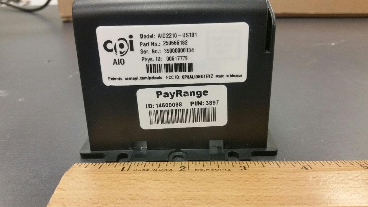
QP8ALIONOTEVZ
Jul 12, 2021ALIO Note is a cashless and telemetry system from CPI
Equipment Class
TNB - Licensed Non-Broadcast Station Transmitter
QP8CORABTATT
Jun 11, 2020CORA modular data port
Equipment Class
PCB - PCS Licensed Transmitter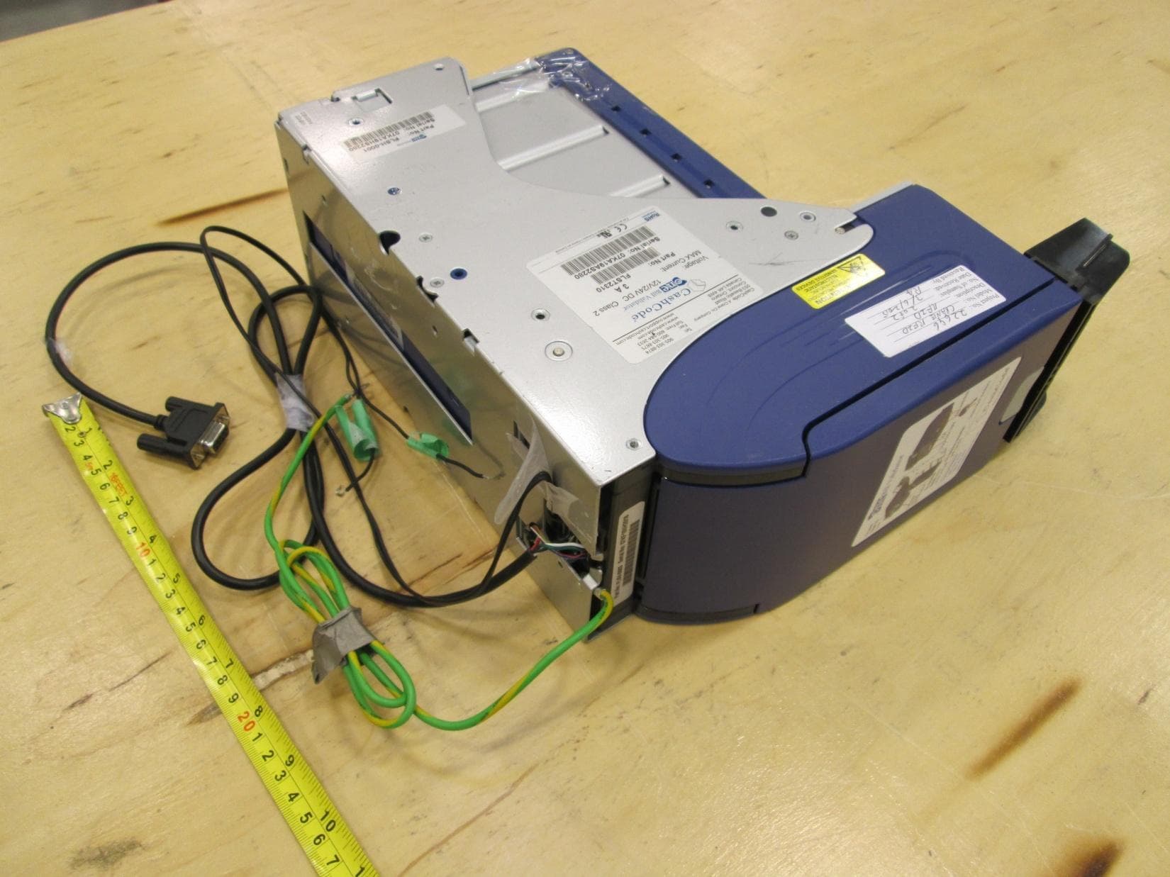
QP8ONETRACK
Jun 30, 2015RFID system
Equipment Class
DXX - Part 15 Low Power Communication Device Transmitter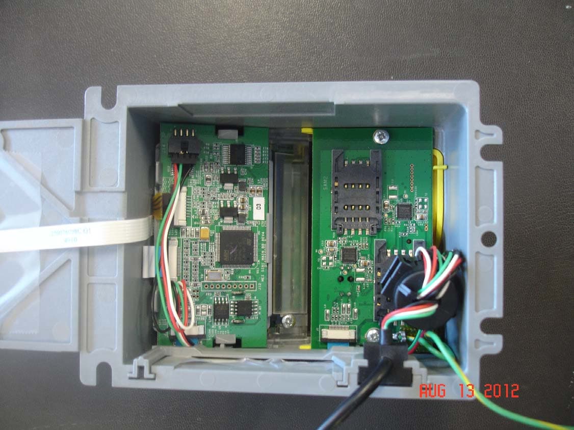
QP85IN1
Sep 04, 20125 in 1 Credit Card Bezel
Equipment Class
DXX - Part 15 Low Power Communication Device Transmitter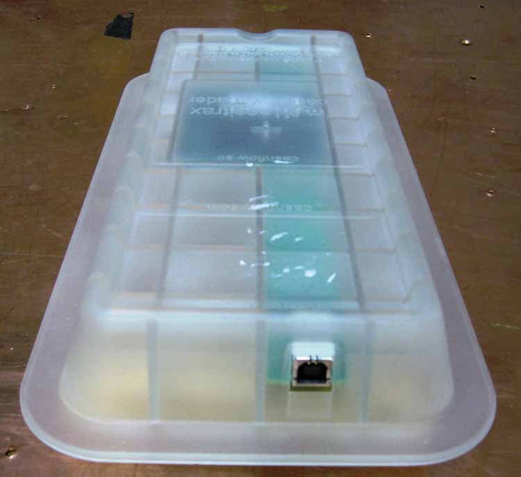
QP8EASITRAXRB
Oct 19, 2007RFID System
Equipment Class
DXT - Part 15 Low Power Transceiver, Rx Verified