QP8EASITRAXRFID System
Crane Payment Innovations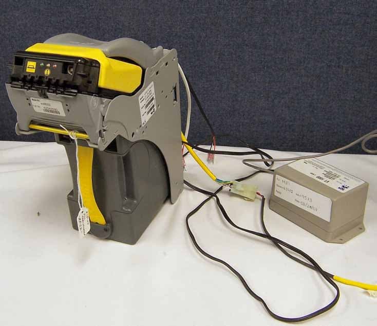
Click to zoom
Application Details
- Equipment Class
- DXX - Part 15 Low Power Communication Device Transmitter
- Date of Grant
- May 26, 2007
- Application Purpose
- Original Equipment
- Date of Application
- May 22, 2007
- Equipment Note
- RFID System
- Frequency Range
- 13.56000000 - 13.56000000
- Company
- Crane Payment Innovations
- Country
- United States
Documents & Files
Document Text
Text extracted from the exhibit documents filed with the FCC. Open a document above to read the original.
Users Manual
Installation Guide © 2007 MEI. All rights reserved Part # 252056111 2 Table of Contents TABLE OF CONTENTS ............................................................................................................................................ 2 GENERAL INFORMATION..................................................................................................................................... 3 REQUIRED KIT NUMBERS .................................................................................................................................... 3 REQUIRED TOOLS................................................................................................................................................... 3 SC66/83 ACCEPTOR REMOVAL............................................................................................................................ 3 EASITRAX SC HARDWARE INSTALLATION.................................................................................................... 3 EASITRAX SC SOFTWARE CONFIGURATION................................................................................................. 6 MMI CODES ............................................................................................................................................................... 8 COMPLIANCE ........................................................................................................................................................... 9 3 General Information This document contains information for installing the MEI easitrax SC hardware and configuration of the software that will support a retrofit application of the SC66/83 bill acceptor with RFID. NOTE: Only properly trained technicians certified by MEI are authorized to install the retrofit hardware. Installations performed by anyone else may void the warranty and the grant to use this equipment. Required Kit Numbers easitrax SC upgrade kit. Qty. 1 Part number - 91702200P10 Contains: ¾ 10 Antenna PCBs ¾ 10 easitrax SC cashbox labels ¾ 10 FCC ID labels ¾ 10 Alcohol wipes. ¾ 10 RF tags ¾ 30 Plastic standoffs (pre-installed on antenna PCB) ¾ 60 Plastic screws (pre-installed on antenna PCB) ¾ 20 Ferrite's Required Tools Regular blade screwdriver size 1/8" SC66/83 Acceptor Removal 1. Turn power off to the Slot machine 2. Remove the current MEI SC bill acceptor from the slot machine. 3. Remove the Interface PCB from the chassis. Easitrax SC Hardware Installation Note: The Antenna PCB will come packaged with the standoffs and screws already mounted. Remove the screws from the end of the standoffs that are not mounted to the PCB. These screws were installed for shipping purposes only, and you will use these screws in the steps that follow. 1. If you haven't done so yet, read the note above and remove the three screws from the standoffs as described. 4 2. Use fig.1 below as a guide to line up the pins that are on the top of the antenna PCB with the matching holes that are located on the bottom of the Interface PCB. Mate the PCBs together by pressing the PCBs together. 3. Use the screws from step one and mount the topside of the antenna PCB to the bottom side of the SC series interface PCB. 4. Reinstall the Interface/Antenna PCB back into the chassis as shown in fig.2A 5. Apply the FCC ID label to the top of the chassis. See fig.2B Screws Standoffs Antenna PCB Interface PCB fig.1 Antenna PCB Pins. Interface PCB matchin g holes fig.2A fig.2B 5 6. Open the cashbox door and remove the yellow pressure plate and spring by sliding it out. 7. Using an alcohol wipe, clean the area where the RF tag will be mounted that is shown in fig. 3. Note: Allow alcohol to completely dry before mounting the RF tag into position. 8. Mount the RF tag and reinstall the pusher plate and spring. See fig.3 Note: Mount the RF tag in the location shown to ensure proper communication with the antenna board. 9. Mount the easitrax SC label, locating it just above the bottom of the yellow cashbox handle. See fig.3 10. Install the two ferrite's onto the interface harnessses as shown in fig. 4A and 4B. fig 4A is for 6602's, and Fig. 4B is for 6604's and 6607's. 11. Enclose the yellow sheathed harness together in one ferrite and the black and white harnesses together in the other ferrite for the 6604 and 6607 Interface harness. See fig. 4B 12. For the 6602 Interface harness, cut the two black tie-raps that hold the USB and yellow sheathed harness together. 13. After the tie-raps have been removed, mount the two ferrites to the harness's as shown in fig. 4A. Place one ferrite around the yellow sheathed harness and the second ferrite around the three remaining black harness's. fig.3 RF tag location easitrax SC label location fig. 4B fig.4A 6 Easitrax SC Software Configuration 1. Open the STS program and connect to the SC series bill acceptor through the USB port. 2. Select the open button from the main screen as shown in fig. 4 3. Select the approved .xcf easitrax SC software file that is approved for your jurisdiction and click OK. 4. Select the edit box for the cashbox settings . See fig.4 5. Select the include/change box and type in the machine asset number and select OK. See fig. 5 6. The machine asset number that you typed will now show under the cashbox settings section. fig.4 fig.5 7 Note: The machine's asset number will now be assigned to that particular cashbox and will be referred to as the cashbox asset number shown in fig.5. 7. Select the write button from the main screen. See fig.6 8. Wait for the SC66 to perform a run &stack. The software configuration is complete. 9. Select the read button and verify the machine asset number is correctly displayed under the cashbox settings section. fig. 6 8 MMI Codes ENABLED / DISABLED? MMI CODE ACTION / RESULT DISABLED 5 RED BLINKS NO RF TAG DETECTED ENABLED GREEN HEAD, BLOCK 1 AND BLOCK 2 CONTAIN CORRECT ASSET NUMBER ENABLED GREEN HEAD, BLOCK 1 AND BLOCK 2 CONTAIN CORRECT ASSET NUMBER ENABLED GREEN HEAD, BL…
Text truncated - open the document above for the full version.
Cover Letter(s)
Date: 17 May 2007 To: American Telecommunications Certified Body 6731 Whittier Avnue Suite C110 McLean, Virginia 22101 From: MEI 1301 Wilson Drive West Chester, Pa. 19380 Subject: Certification Application – FCC ID: QP8EASITRAX Request for Confidentiality per CFR 47, 0.457 & 0.459 Please be advised that the following information is requested to be held confidential on behalf of MEI. • Schematics • Block Diagram • Operational Description The application contains technical information which MEI deems to be trade secrets and proprietary. If made public, the information might be used to the disadvantage of the applicant in the market place. Thank you for your attention in this mater. Robert M. Carney Product Compliance Manager Tel: 610-430-2697 Fax: 601-430-2795 e-mail: [email protected] U:/Pro2007US Letter Request for Confidentiality_SC66XX RFID_rev2.doc 1301 Wilson Drive, West Chester, Pennsylvania 19380-5963 Tel: (610) 430-2500 · Fax: (610) 430-2694 www.meigroup.com
Cover Letter(s)
Date: 23 January 2007 To: American Telecommunications Certified Body 6731 Whittier Avnue Suite C110 McLean, Virginia 22101 From: MEI 1301 Wilson Drive West Chester, Pa. 19380 Subject: Letter of Agency To Whom it may concern, Please be advised that MEI authorizes Washington Laboratories, Ltd. to act on our behalf, until otherwise notified, for applications submitted to American Telecommunications Certified Body, Inc. (ATCB) We certify that we are not subject to denial of federal benefits, that includes FCC benefits, pursuant to Section 53011 of the Anti-Drug Abuse ACT of 1988, U.S.C. 862. Further, no party, as defined in 47 CFR 1.2002(b), to the application is subject to denial of federal benefits, that includes FCC benefits. Thanks you for your attention to this matter. Robert M.Carney Product Compliance Manager Tel: 610-430-2697 Fax: 601-430-2795 e-mail: [email protected] 1301 Wilson Drive, West Chester, Pennsylvania 19380-5963 Tel: (610) 430-2500 · Fax: (610) 430-2694 www.meigroup.com
Cover Letter(s)
Response to ATCB Comments FCC ID: QP8EASITRAX 1 Washington Laboratories, Ltd. 7560 LINDBERGH DRIVE GAITHERSBURG, MD 20879 (301) 417 – 0220 FAX # (301) 417 - 9069 May 18, 2007 Mr. Rich Fabina American Telecommunications Certification Body Inc. 6731 Whittier Ave McLean, VA 22101 RE: Comments of April 27, 2007 APPLICATION: QP8EASITRAX Mars Electronics, Inc. Dear Mr. Fabina: Below are the comments that you have provided regarding the application for certification referenced above. Our responses to those comments are in bold italic. Many responses refer you to additional exhibit(s) which has been uploaded to the application folder at the ATCB website. Thank you for your attention. Please feel free to contact us for any additional information that you may require. Regards, Steven D. Koster EMC Operations Manager Brian J. Dettling Documentation Specialist WLL Project: 9554 1) The AC line conducted limits for a Part 15 intentional radiator are contained in Section 15.207of the FCC Rules. These limits are comparable to the Class B limits for a digital device. You cannot apply the Class A digital device limits to a Part 15 intentional radiator. The good news is that all the transmitter AC line conducted emissions comply with the 15.207 limits except the emission at 13.56 MHz. You must remeasure the emission at 13.56 MHz with the transmitter disabled and prove that the emission is coming from the Class A digital device (gaming machine). Alternatively, you may terminate the antenna with a resistive load so it doesn’t radiate and contribute to the AC line conducted level at 13.56 MHz. If the emission is coming from the transmitter, AC line filtering will have to be added to the device and it must be retested. R. The unit was retested as per the information above. Please see “EASITRAX Test Report revised.pdf”. Response to ATCB Comments FCC ID: QP8EASITRAX 2 2) Please confirm that this device will not be installed by the end user but by technicians or installers working under contract to the Grantee. Application of the FCC ID label by the end user is not permitted by the Commission. R. The User Manual has been revised to clarify. Please see “EASITRAX User Manual Rev 1.pdf” 3) Both the occupied bandwidth plot and the frequency stability test data show the fundamental emission at 13.5603 MHz but radiated emissions in Table 5 show the fundamental at 13.587 MHz (which is not even in the fundamental emission band of 13.553 to 13.567 MHz of Section 15.225(a)). Please explain and correct as necessary. R. Please see the revised report for corrected data. 4) Please provide a more detailed description of the pulse modulation and pulse repetition frequency (PRF) used by this device for normal operation and testing. The note at the end of Section 15.35(a) of the FCC Rules states for CISPR quasi-peak limits the PRF of a pulsed emission must be greater than 20 Hz or peak measurements must be made and compared to the quasi-peak limit. R. The Operational Description has been revised to address this. Please see “EASITRAX Operational Description Rev 1.pdf”. 5) Please provide a new letter requesting confidentiality that references FCC Rule Sections 0.457 and 0.459. The confidentiality letter provided doesn’t mention any rules. R. Please see “EASITRAX Cover Letter - RFC Rev 1.pdf” 6) Please provide a block diagram that shows the frequency of all oscillators in the device in accordance with Section 2.1033(b)(5) of the FCC Rules. The diagram provided contains no oscillators. R. A corrected Block Diagram has been supplied. Please see “EASITRAX Block Diagram Rev 1.pdf” 7) Please identify the loop antenna used for measuring emissions below 30 MHz. No loop antenna is listed in the test equipment shown on page 6 of the test report. R. Table 2 in the revised report has been edited to include the EMCO Active Loop antenna. 8) Please describe how the loop antenna was manipulated for making measurements below 30 MHz. R. The loop antenna was manipulated in the X, Y and Z axis per the data table. 9) Please confirm that the ferrite beads shown on the interface cables connected between the transmitter and the gaming device will be provided with the transmitter and provide installation instructions for them in the user’s manual. R. Please see the revised user manual.
Cover Letter(s)
Response to ATCB Comments FCC ID: QP8EASITRAX 1 Washington Laboratories, Ltd. 7560 LINDBERGH DRIVE GAITHERSBURG, MD 20879 (301) 417 – 0220 FAX # (301) 417 - 9069 May 23, 2007 Mr. Rich Fabina American Telecommunications Certification Body Inc. 6731 Whittier Ave McLean, VA 22101 RE: Comments of May 22, 2007 APPLICATION: QP8EASITRAX Mars Electronics, Inc. Dear Mr. Fabina: Below are the comments that you have provided regarding the application for certification referenced above. Our responses to those comments are in bold italic. Many responses refer you to additional exhibit(s) which has been uploaded to the application folder at the ATCB website. Thank you for your attention. Please feel free to contact us for any additional information that you may require. Regards, Steven D. Koster EMC Operations Manager Brian J. Dettling Documentation Specialist WLL Project: 9554 1) Table 5 entitled radiated emissions test data, fundamental frequency on page 10 of the test report has a spectrum analyzer level of 270 dBuV. That and the listed correction factors do not add up to the listed value of the emission (270+1+26 does not equal 10.9). I suspect you have incorrectly listed the azimuth of the emission instead of the spectrum analyzer reading. Please correct the test report and resubmit it. R. The table has been corrected. Please see “EASITRAX Test Report Rev 1.pdf”.
External Photos
External Photos ©2007 Washington Laboratories, Ltd FCC ID: QP8EASITRAX External Photos ©2007 Washington Laboratories, Ltd FCC ID: QP8EASITRAX External Photos ©2007 Washington Laboratories, Ltd FCC ID: QP8EASITRAX External Photos ©2007 Washington Laboratories, Ltd FCC ID: QP8EASITRAX
ID Label/Location Info
NOTES: 1. LABEL TO BE PRINTED AS SHOWN AT MANUFACTURING LOCATION. PRINTING COLOR: BLACK 2. MATERIAL: 3M #7815 WHITE THERMAL IMPRINTABLE MYLAR, 0.05mm THICK, COLOR: WHITE ADHESIVE: PERMANENT PRESSURE SENSITIVE ACRYLIC WITH PEEL OFF BACKING. 3. LABELS TO BE SUPPLIED ON LINERS WOUND ON A 76.2mm HOLLOW CORE. NO SPLICES. ROLL DIAMETER 228.6mm MAX. 4. SEE MEI SPECIFICATION # 112659001 EXAMPLE NO. 4 FOR PREFERRED RUN DIRECTION. 5. SEE MEI SPECIFICATION 002584062 FOR COMPLIANCE REQUIREMENTS FOR RESTRICTED MATERIALS AND RECYCLING NOTES. ±1 ±141.0 22.0 R2.50 MIN ROB CLAUSER - - 1/18/07 - : - EASITRAX CASHBOX WCR - PRODUCTION - - - 000.000 LABEL, FCC ID 252058110 G2 4:1 1 JEFF THAWEY JEFF THAWLEY 1/18/07 1/18/07 CS - --- A B C D E F G H 4321 4 3 21 H G F E D C B ECN 0.10 XX.XX CHANGE HISTORY IF IN DOUBT ASK AFTER INITIAL RELEASE A CHECKEDDATEREVECN INITIAL END PRODUCT: NO LONGER NEEDED. NOTICE OF CONFIDENTIALITY: MATERIAL / FINISH: TOOLING INFORMATION MARS ASSET # VENDORS TOOL REF. RELEASED FOR: UNLESS OTHERWISE SPECIFIED : THIS DRAWING REPLACES: 1301 WILSON DRIVE WEST CHESTER, PA 19380 USA PHONE: +1 (610) 430 2508 FAX: +1 (610) 430-2795 INTERNATIONAL ELECTRONICS MARS TITLE SIZEDESIGN CENTERDOC CLASSDWG NO.REV °DIMENSIONS ARE IN MILLIMETRES OR DEGREES °3RD ANGLE PROJECTION °LINEAR & ANGULAR SEE MEI MRP DATABASE FOR DO NOT MEASURE OFF THIS PRINT DESTROYED OR RETURNED TO MARS ELECTRONICS INTERNATIONAL WHEN IT IS TOLERANCES THE DOCUMENT SHOULD ALWAYS BE KEPT IN A SECURE PLACE, AND SHOULD BE 0.50 XX. 0.20 XX.X 0.05 °GEOMETRIC DIMENSIONS AND TOLERANCES PER ANSI Y14.5M-1994 AND ISO 8015 REFERENCE PART NO.: DRAWN: CHECKED: PROJECT ENGINEER: DATE DATE DATE SCALE: VOLUME: (CUBIC MM) SHEET 1 OF A REVDATECHECKED THIS DOCUMENT AND THE INFORMATION CONTAINED IN IT ARE CONFIDENTIAL AND ARE THE PROPERTY OF MARS ELECTRONICS INTERNATIONAL. THEY MAY NOT BE IN ANY WAY DISCLOSED, COPIED OR USED BY ANYONE EXCEPT AS EXPRESSLY AUTHORIZED BY MARS ELECTRONICS INTERNATIONAL. XX.XXX -SEE NOTES Label Location
Internal Photos
Internal Photos ©2007 Washington Laboratories, Ltd FCC ID: QP8EASITRAX Internal Photos ©2007 Washington Laboratories, Ltd FCC ID: QP8EASITRAX Internal Photos ©2007 Washington Laboratories, Ltd FCC ID: QP8EASITRAX Internal Photos ©2007 Washington Laboratories, Ltd FCC ID: QP8EASITRAX Radio Card / Antenna Side (Mounted on Parent Board) Internal Photos ©2007 Washington Laboratories, Ltd FCC ID: QP8EASITRAX Parent Board Internal Photos ©2007 Washington Laboratories, Ltd FCC ID: QP8EASITRAX Radio Card Removed From Parent Board Internal Photos ©2007 Washington Laboratories, Ltd FCC ID: QP8EASITRAX Radio Card
Test Report
FCC Certification Test Report For the Mars Electronics (MEI) easitrax™ FCC ID: QP8EASITRAX WLL JOB# 9554 April 19, 2007 Prepared for: Mars Electronics (MEI) 1301 Wilson Drive West Chester, PA 19380 Prepared By: Washington Laboratories, Ltd. 7560 Lindbergh Drive Gaithersburg, Maryland 20879 Mars Electronics (MEI) easitrax™ FCC Certification Test Report April 2007 FCC Certification Test Report for the Mars Electronics (MEI) easitrax™ FCC ID: QP8EASITRAX April 19, 2007 WLL JOB# 9554 Prepared by: Brian J. Dettling Documentation Specialist Reviewed by: Steven D. Koster EMC Operations Manager Mars Electronics (MEI) easitrax™ FCC Certification Test Report April 2007 WLL Report #9554-01 - ii - © 2007 Washington Laboratories, Ltd. Abstract This report has been prepared on behalf of Mars Electronics (MEI) to support the attached Application for Equipment Authorization. The test report and application are submitted for an Intentional Radiator under Part 15.225 of the FCC Rules and Regulations. This Certification Test Report documents the test configuration and test results for a Mars Electronics (MEI) easitrax™. Testing was performed on an Open Area Test Site (OATS) of Washington Laboratories, Ltd, 7560 Lindbergh Drive, Gaithersburg, MD 20879. Site description and site attenuation data have been placed on file with the FCC's Sampling and Measurements Branch at the FCC laboratory in Columbia, MD. Washington Laboratories, Ltd. has been accepted by the FCC and approved by NIST NVLAP (NVLAP Lab Code: 200066-0) as an independent FCC test laboratory. The Mars Electronics (MEI) easitrax™ complies with the limits for an Intentional Radiator device under FCC Part 15.225. Mars Electronics (MEI) easitrax™ FCC Certification Test Report April 2007 WLL Report #9554-01 - iii - © 2007 Washington Laboratories, Ltd. Table of Contents Abstract ........................................................................................................................................... ii 1 Introduction..........................................................................................................................1 1.1 Compliance Statement .....................................................................................................1 1.2 Test Scope ........................................................................................................................1 1.3 Contract Information........................................................................................................1 1.4 Test Dates ........................................................................................................................1 1.5 Test and Support Personnel .............................................................................................1 1.6 Abbreviations ...................................................................................................................2 2 Equipment Under Test .........................................................................................................3 2.1 EUT Identification & Description ...................................................................................3 2.2 Test Configuration ...........................................................................................................3 2.3 Testing Algorithm............................................................................................................4 2.4 Test Location ...................................................................................................................4 2.5 Measurements ..................................................................................................................5 2.5.1 References....................................................................................................................5 2.6 Measurement Uncertainty................................................................................................5 3 Test Equipment ....................................................................................................................6 4 Test Results ..........................................................................................................................7 4.1 Occupied Bandwidth........................................................................................................7 4.2 Radiated Spurious Emissions: §15.225, §15.209 ............................................................9 4.2.1 Test Procedure...........................................................................................................9 4.2.2 Test Results ................................................................................................................10 4.3 Frequency Stability: (FCC Part §2.1055) ......................................................................12 4.3.1 Test Procedure ...........................................................................................................12 4.3.2 Test Results ................................................................................................................12 4.4 Conducted Emissions (AC Power Line) ........................................................................14 List of Tables Table 1. Device Summary............................................................................................................... 3 Table 2: Test Equipment List.......................................................................................................... 6 Table 3: Occupied Bandwidth Results............................................................................................8 Table 4: Radiated Spurious Emissions Limits ................................................................................ 9 Table 5: Radiated Emission Test Data, Fundamental Frequency ................................................. 10 Table 6: Radiated Emission Test Data......................................................................…
Text truncated - open the document above for the full version.
Test Setup Photos
Test Setup Photos ©2007 Washington Laboratories, Ltd FCC ID: QP8EASITRAX Test Setup Photos ©2007 Washington Laboratories, Ltd FCC ID: QP8EASITRAX Test Setup Photos ©2007 Washington Laboratories, Ltd FCC ID: QP8EASITRAX
Contact Information
Applicant
Robert M Carney(Global Compliance Manager)
Technical Contact
Washington Laboratories, Ltd.Gregory M. Snyder
[email protected]301-417-0220
7560 Lindbergh Drive · Gaithersburg · United States
Test Firm
Washington Laboratories, Ltd.John Repella
Technical Specifications
| # | Rule Parts | Frequency Range | Power Output |
|---|---|---|---|
| 1 | 15C | 13.56 MHz - 13.56 MHz | - |
Other Applications from Crane Payment Innovations
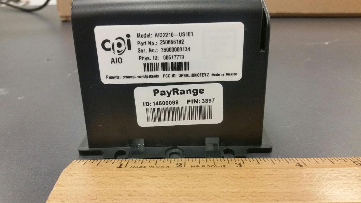
QP8ALIONOTEVZ
Jul 12, 2021ALIO Note is a cashless and telemetry system from CPI
Equipment Class
TNB - Licensed Non-Broadcast Station Transmitter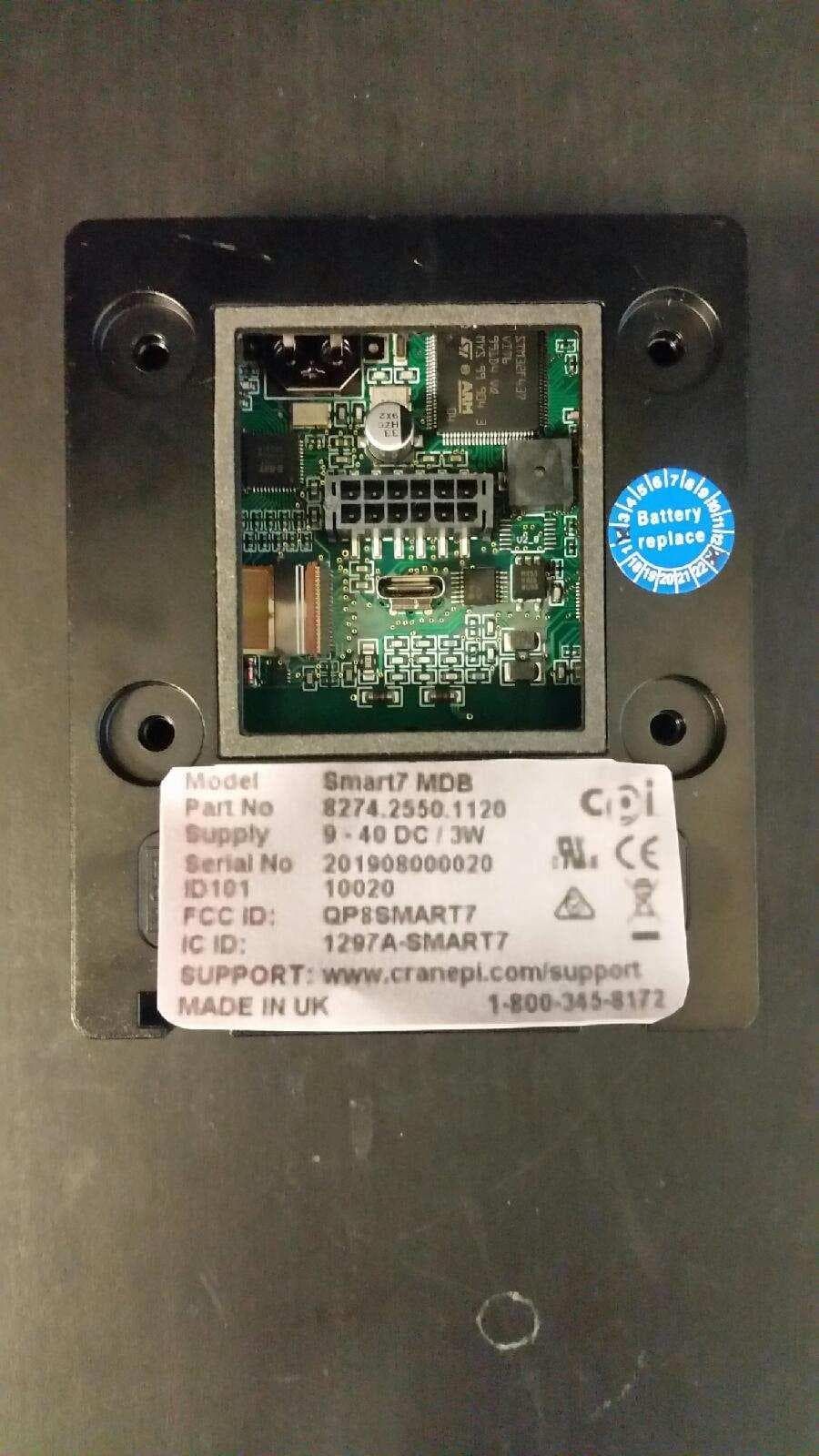
QP8SMART7
Jul 22, 2020SMART7 Card Reader Bezel
Equipment Class
DXX - Part 15 Low Power Communication Device Transmitter
QP8CORABTATT
Jun 11, 2020CORA modular data port
Equipment Class
PCB - PCS Licensed Transmitter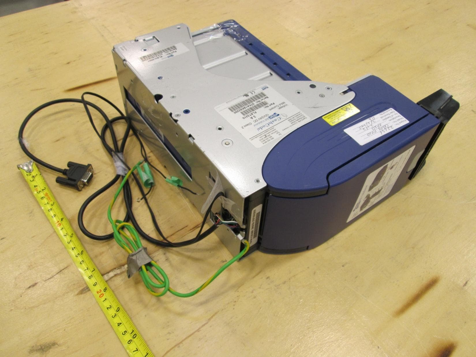
QP8ONETRACK
Jun 30, 2015RFID system
Equipment Class
DXX - Part 15 Low Power Communication Device Transmitter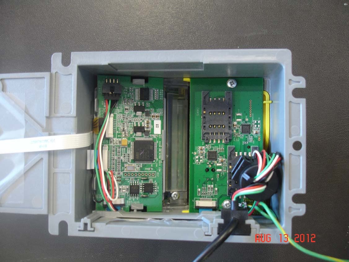
QP85IN1
Sep 04, 20125 in 1 Credit Card Bezel
Equipment Class
DXX - Part 15 Low Power Communication Device Transmitter