QPRDL18TransPod2
Jow Tong Technology Co.,Ltd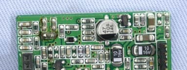
Click to zoom
Application Details
- Equipment Class
- DXX - Part 15 Low Power Communication Device Transmitter
- Date of Grant
- Aug 24, 2005
- Application Purpose
- Original Equipment
- Date of Application
- Aug 24, 2005
- Equipment Note
- TransPod2
- Frequency Range
- 88.10000000 - 107.90000000
- Company
- Jow Tong Technology Co.,Ltd
- Country
- Taiwan
Documents & Files
Document Text
Text extracted from the exhibit documents filed with the FCC. Open a document above to read the original.
Users Manual
MINI INSERT FIT PAD EXTENSION ARM C | 3 Contents 2|DLO TRANSPOD USER MANUAL ©2005 DIGITAL LIFESTYLE OUTFITTERS TransPod, Digital Lifestyle Outfitters & DLO logo are trademarks of Digital Lifestyle Outfitters. iPod is a registered trademark of Apple Computer, Inc. All Rights Reserved Printed in Taiwan A3030-050804-B Quick Start4 Using Your DLO TransPod About FM Transmitters and the TransPod6 Setting Up Your TransPod6 Finding Empty Radio Frequencies8 Tuning Your TransPod 9 TransPod Features and Settings Setting Preset Stations10 Controlling the LCD Backlight10 TransPod Intelligent Power Control11 Getting the Best Sound Quality11 Using a Cassette Adapter or Direct Input12 Using other MP3 Players orDevices12 Tips and Troubleshooting13 Tech Specs15 Warranty17 FCC Statement18 MINI INSERT FIT PAD EXTENSION ARM CHARGER ARM TRANSPOD CRADLE MINI INSERT FIT PAD EXTENSION ARM C | 5 4|DLO TRANSPOD USER MANUAL Quick Start Thank you for your purchase of the DLO TransPod, the best all-in-one iPod auto accessory in the world. We’ll get you up and running in 4 easy steps: 1. Connect the Charger Arm to the TransPod Cradle. 2.Adjust the TransPod to fit into your Auto Power Outlet and plug it in. 3.Tune your car stereo to 88.5 FM. 4.Slide your iPod or iPod mini into the TransPod and press Play. You can now enjoy your iPod’s music played through your car stereo, while it’s charging and securely cradled. For more detailed instructions and tips, please read Setting Up Your TransPod [pg 6]. MINI INSERT FIT PAD EXTENSION ARM C | 7 6|DLO TRANSPOD USER MANUAL Using Your TransPod About the DLO TransPod FM Transmitter The TransPod is basically a mini radio station that broadcasts your iPod or iPod mini’s audio to the FM radio in your car, truck, boat – anything that has a 12v Auto Power Outlet. It also charges the battery in your iPod while cradling it for easy access in your car. The TransPod has two triangular buttons either side of its LCD screen for easy tuning.Other features include four programmable presets, controllable LCD backlight, external device input, cassette or line-out, and power control. Setting up your TransPod 1. Connect the Charger Arm to the TransPod Cradle. Take the Charger Arm, insert the flat side into the back of the TransPod Cradle body and turn 90 degrees clockwise to lock it into place. Do not use the included Extension Arm until you have determined that you’ll need it to fit TransPod into your car. Most cars will do fine with just the shorter Charger Arm. 2. Adjust your TransPod to fit into your Auto Power Outlet and plug it in. Loosen the Charger Arm knobs to adjust the angle the TransPod for the best placement and access to your iPod. Adjusting the arm angles is easi- er when the TransPod is not plugged into the Auto Power Outlet. When you’ve found a good fit, tighten the knobs back up again and then plug the Transpod into your Auto Power Outlet. If you have trouble finding a com- fortable position for the TransPod, or it happens to block controls in your car, use the TransPod Extension Arm to achieve other positioning options. 3. Tune your car stereo to 88.5 FM. This is the default broadcast frequency for the TransPod. If your TransPod is already plugged in, you should hear silence. If 88.5 is not an empty fre- quency in your area (i.e. there is music or talk already on that station in your area) you may hear static. Try finding another station in your area with less interference. For help doing this, please see Finding Empty Radio Frequencies [pg 8]. 4. Slide your iPod or iPod mini into the TransPod’s Cradle and press play. •For larger iPods (40GB, 60GB for example), remove the mini insert then slide your iPod right in •For thinner iPods (10GB, 15BG, 20BG, 30GB), remove the mini insert, attach the included Fit Pad for a perfect fit and slide your iPod in •iPod mini owners - use the included mini insert to securely fit your iPod mini into your TransPod You can now enjoy your iPod’s music played through your car stereo, while it’s charging and securely cradled in your car. Control your iPod with its Click Wheel, just as you normally would except for the volume. Use your car stereo to adjust the volume instead of the iPod. Your TransPod is using the superior line-out audio from the bottom of your iPod which is not controlled by your iPod’s volume control on its Click Wheel. MINI INSERT FIT PAD EXTENSION ARM C | 9 8|DLO TRANSPOD USER MANUAL Finding Empty Radio Frequencies If you live in a big city with a lot of radio stations, finding an empty FM frequen- cy can be tricky. What is an empty frequency? It’s a frequency on your car radio where you can’t hear a radio station, where there is only static, not even a faint radio station can be heard. Here are some tips for finding an empty frequency: • Be sure to search the entire spectrum of FM frequencies, from 88.1 to 107.9. Don’t just look to the low end of the dial. There are often empty FM stations in the 100’s that will work great. • When using the scan function on your car stereo, if you’re tuner stops on 101 and then jumps to 103, look in the 102 range of frequencies for an empty frequency. •Try scanning to a strong station, then backing down two frequencies - for example 103.5 to 103.1. You can often find empty frequencies this way. If that frequency is taken, try scanning to the next station and try again. • Save a preset station on your radio when you find a frequency that works well in your area. Then set these presets on your TransPod for different driving areas (ie. CH01 for home, CH02 for commute, etc). To learn how to set your presets on your TransPod read Setting Preset Stations[pg 10]. Tuning Your TransPod To tune your TransPod, use the triangular tuning buttons on either side of the LCD display on the front of the TransPod Cradle. Use the right button for tun- ing up, left button for tuning down. The TransPod also has 4 preset stations you can try. The default frequencies for these presets are 88.1, 94.9, 100.9, and 107.9. To…
Text truncated - open the document above for the full version.
Cover Letter(s)
Helen Zhao Subject: FW: Re : FW: JOW TONG TECHNOLOGY CO., LTD. , FCC ID: QPRDL18 , Assessment NO.: AN05T5090, Notice#1- -Updated(0825) 8/25/2005 Dear Helen: Thank you for your notice.Please find the attached for updated(0825). And if still have any problems,please connect with me,thank you for your support. BEST REGARDS Daphne Liang / ??? 8/25/2005 Question #1: The Operational Description indicates that "By the setting of microcontroller, the inner PLL of U1 can stably control the VCO output frequency, which is 88MHz~108MHz." Please confirm whether the device can operate at 88MHz and 108MHz. Ans:Sorry for confused you,the device operate at 88.1MHz - 107.9MHz. Please find the attached for updated:DL-18_Operational Description(0825). Question #2: The confidentiality letter lists PCB Layout as one of the technical documents that need to be kept confidential. However PCB layout is not submitted with the filing. Please either revise the letter to remove PCB layout from the list or submit PCB layout exhibit. Ans:Please find the attached for updated:DL-18_Confidentiality letter(0825). Question #3: The test report both page 13 & 18 show Horn antenna is past due (last calibration date: AUG. 02, 2004). Please explain. Ans:Sorry for our typing error.Please find the attached for updated:DL-18_Report(RP1)0825. Best Regards, Helen Zhao The items indicated above must be submitted before processing can continue on the above referenced application. Failure to provide the requested information within 30 days of the original e-mail date may result in application dismissal and forfeiture of the filing fee. Also, please note that partial responses increase processing time and should not be submitted. Any questions about the content of this correspondence should be directed to the e-mail address listed below the name of the sender.
External Photos
Compliance Certification Services Inc.Report No.50816404-RP1 External Photo
ID Label/Location Info
Company : JOW TONG TECHNOLOGY CO., LTD. Model : DL-18 Product : TransPod2 TransPod2 Model No: DL-18 FCC IDQPRDL18 This device complies with part 15 of the FCC Rules. Operation is subject to the following two conditions: [1] this device may not cause harmful interference and [2] this device must accept any interference received, including interference that may cause undesired operation. S/N Made in Taiwan Label Here
Internal Photos
Compliance Certification Services Inc.Report No.50816404-RP1 Internal Photo Compliance Certification Services Inc.Report No.50816404-RP1 Compliance Certification Services Inc.Report No.50816404-RP1 Compliance Certification Services Inc.Report No.50816404-RP1 Compliance Certification Services Inc.Report No.50816404-RP1
Test Report
Compliance Certification Services Inc. Report No.: 50816404-RP1 FCC ID: QPRDL18 Date of Issue: August 22, 2005 Note: This report shall not be reproduced except in full, without the written approval of Compliance Certification Services Inc. This document may be altered or revised by Compliance Certification Services Inc. personnel only, and shall be noted in the revision section of the document. Page 1 FCC CFR 47 PART 15 SUBPART C TEST REPORT For TransPod2 Model: DL-18 Issued to JOW TONG TECHNOLOGY CO., LTD. 46, Lane 337, Chung Rd., Yung Kang City, Tainan County 710, Taiwan, R.O.C. Issued by Compliance Certification Services Inc. No. 8, Jiu Ceng Ling, Jiaokeng Village,Sinhua Township, Tainan Hsien 712, Taiwan R.O.C. TEL: 886-6-580-2201 FAX: 886-6-580-2202 Compliance Certification Services Inc. Report No.: 50816404-RP1 FCC ID: QPRDL18 Date of Issue: August 22, 2005 Page 2 TABLE OF CONTENTS 1. TEST RESULT CERTIFICATION .................................................................................. 3 2. EUT DESCRIPTION ........................................................................................................ 4 3. TEST METHODOLOGY................................................................................................. 5 3.1 EUT CONFIGURATION................................................................................... 5 3.2 EUT EXERCISE............................................................................................. 5 3.3 GENERAL TEST PROCEDURES......................................................................... 5 3.4 FCC PART 15.205 RESTRICTED BANDS OF OPERATIONS.............................. 6 3.5 DESCRIPTION OF TEST MODES........................................................................ 6 4 INSTRUMENT CABLIBRATION ................................................................................. 7 5 FACILITIES AND ACCREDITATIONS ...................................................................... 8 5.1 FACILITIES.................................................................................................. 8 5.2 EQUIPMENT................................................................................................. 8 5.3 LABORATORY ACCREDITATIONS AND LISTINGS................................................ 8 5.4 TABLE PF ACCREDITATIONS AND LISTINGS...................................................... 9 6 SETUP OF EQUIPMENT UNDER TEST ................................................................... 10 6.1 SETUP CONFIGURATION OF EUT................................................................... 10 6.2 SUPPORT EQUIPMENT................................................................................. 10 7 FCC PART 15.239 REQUIREMENTS ......................................................................... 11 7.1 20 DB BANDWIDTH..................................................................................... 11 7.2 BAND EDGES MEASUREMENT............................................................. 13 7.3 RADIATED EMISSIONS................................................................................. 17 7.4 POWERLINE CONDUCTED EMISSIONS............................................................ 23 APPENDIX 1 PHOTOGRAPHS OF TEST SETUP ......................................................... 24 Compliance Certification Services Inc. Report No.: 50816404-RP1 FCC ID: QPRDL18 Date of Issue: August 22, 2005 Page 3 1. TEST RESULT CERTIFICATION Applicant JOW TONG TECHNOLOGY CO., LTD. Address 46, Lane 337, Chung Rd., Yung Kang City, Tainan County 710, Taiwan, R.O.C. Equipment Under Test TransPod2 Model Number DL-18 Date of Test August 16 ~ August 18, 2005 APPLICABLE STANDARDS STANDARD TEST RESULT FCC 47 CFR Part 15 Subpart C No non-compliance noted The above equipment was tested by Compliance Certification Services Inc. The test data, data evaluation, test procedures, and equipment configurations shown in this report were made in accordance with the procedures given in ANSI C63.4 and the energy emitted by the sample EUT tested as described in this report is in compliance with conducted and radiated emission limits of FCC Rules Part 15.239. The test results of this report relate only to the tested sample identified in this report. Approved by: Reviewed by: August 22,2005 August 22,2005 Alex Chiu Jeter Wu Manager Section Manager Compliance Certification Services Inc. Compliance Certification Services Inc. Compliance Certification Services Inc. Report No.: 50816404-RP1 FCC ID: QPRDL18 Date of Issue: August 22, 2005 Page 4 2. EUT DESCRIPTION Product TransPod2 Model Number DL-18 Model Difference N/A Power Supply I/P: 12Vdc Operate Frequency 88.1 ~ 107.9MHz Transmit Power N/A Modulation Technique FM Number of Channels 199 Channel Remark: The product is a Transmitter. This submittal(s) (test report) is intended for FCC ID: QPRDL18 filing to comply with Section 15.239 of the FCC Part 15 Subpart C Rules. Compliance Certification Services Inc. Report No.: 50816404-RP1 FCC ID: QPRDL18 Date of Issue: August 22, 2005 Page 5 3. TEST METHODOLOGY The tests documented in this report were performed in accordance with ANSI C63.4 and FCC CFR 47 Part 15 Subpart C. 3.1 EUT CONFIGURATION The EUT configuration for testing is installed on RF field strength measurement to meet the Commissions requirement and operating in a manner that intends to maximize its emission characteristics in a continuous normal application. 3.2 EUT EXERCISE The calibrated antennas used to sample the radiated field strength are mounted on a non-conductive, motorized antenna mast 3 or 10 meters from the leading edge of the turntable. 3.3 GENERAL TEST PROCEDURES Conducted Emissions The EUT is placed on the turntable, which is 0.8 m above ground plane. According to the requirements in Section 7.1 of ANSI C63.4.Conducted emissions from the EUT measured in the frequency range between 0.15 MHz and 30MHz using CISPR Quasi-Peak detector mode. Radiated Emissions The EUT is a placed on a…
Text truncated - open the document above for the full version.
Test Setup Photos
Compliance Certification Services Inc. Report No.: 50816404-RP1 FCC ID: QPRDL18 Date of Issue: August 22, 2005 Page 24 APPENDIX 1 PHOTOGRAPHS OF TEST SETUP Radiated Emission Setup Photos
Contact Information
Applicant
Shen-Fu Shu(Manager)
Test Firm
Compliance Certification Services Inc.Paul Liau
Technical Specifications
| # | Rule Parts | Frequency Range | Power Output |
|---|---|---|---|
| 1 | 15C | 88.1 MHz - 107.9 MHz | - |
Other Applications from Jow Tong Technology Co.,Ltd
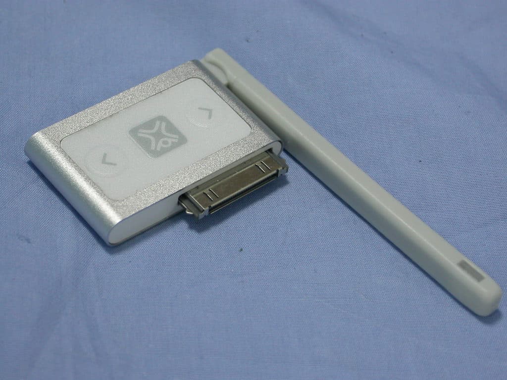
QPR-XT-2605
Mar 20, 2007Airplay
Equipment Class
DXX - Part 15 Low Power Communication Device Transmitter
QPRDL-14
Mar 02, 2006nano TUNE
Equipment Class
DXX - Part 15 Low Power Communication Device Transmitter
QPRST30
Oct 04, 2004Universal Digital FM Transmitter
Equipment Class
DXX - Part 15 Low Power Communication Device Transmitter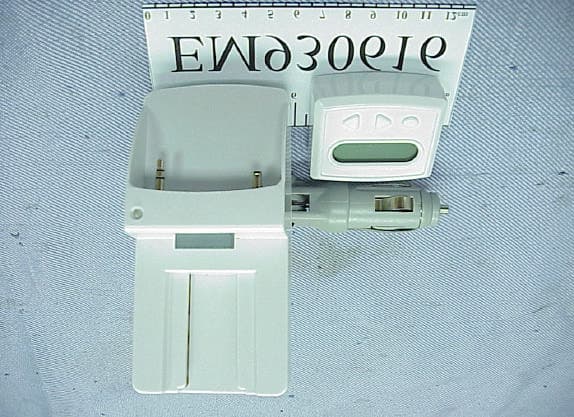
QPRST31
Jul 06, 2004Digital FM Transmitter
Equipment Class
DXX - Part 15 Low Power Communication Device Transmitter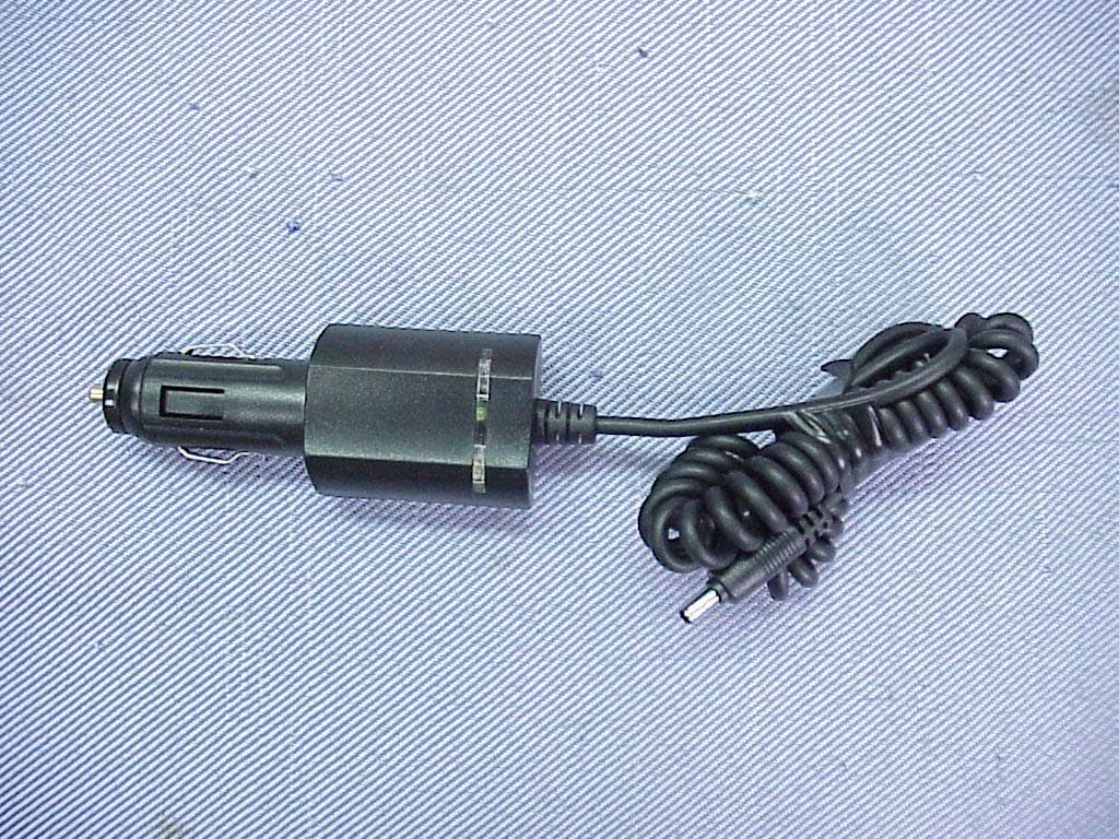
QPRST28
May 21, 2004Multi-Player Transmitter
Equipment Class
DXX - Part 15 Low Power Communication Device Transmitter