QPRST28Multi-Player Transmitter
Jow Tong Technology Co.,Ltd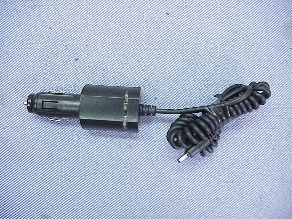
Click to zoom
Application Details
- Equipment Class
- DXX - Part 15 Low Power Communication Device Transmitter
- Date of Grant
- May 21, 2004
- Application Purpose
- Original Equipment
- Date of Application
- May 21, 2004
- Equipment Note
- Multi-Player Transmitter
- Frequency Range
- 88.10000000 - 107.90000000
- Company
- Jow Tong Technology Co.,Ltd
- Country
- Taiwan
Documents & Files
Document Text
Text extracted from the exhibit documents filed with the FCC. Open a document above to read the original.
Users Manual
ST-28 § Multi-Player § User’s Manual 1 Multi-Player Controls Multi-Player C E L E S T V O - L O V = E M U N E T C + L L S E RP T 1 A L L ( ( ( No r m a l MH Z Key Instructions Item Symbol Title Description 1 LCD Display the functions 2 MENU Menu 1.Play mode 2.Frequency setup 3 SELECT Select/Lower Adjust the lower frequency/ Performance mode 4 SELECT Select/Upper Adjust the Upper frequency/ Performance mode 5 Play /Stop Start/stop a song over 6 VOL+ Vol/Next Skip to next song/ Change the volume lower 7 to press simultaneously for seconds VOL- Vol/Prev. or seconds Skip to previous song/ Change the volume louder to press simultaneously f 8 Power socket For external power-supply 9 USB socket USB docking 10 Earphone For earphone use 2 LCD Illustration RPT 1 ALL Norma l ( ( ( MHZ The description of Symbol on LCD Item Symbol Title Description 1 Sound Ready The music is standby Pla ing the music Play mode select s MENU button when the Select the play modePres or 2 Playing y 3 “ ” appears, then press SELECTSELECT 4 button to select the items. Play Mode1.RPT1 2.RPT ALL Volume setting The symbol appears when setup volume. After the symbol disappears, then press the VOL+ or VOL- to adjust the volume level. 5 ( ( ( / Frequency setting W hen setup the frequency, press MENU button twice and then the symbol ( ( ( appears. Press SELECT/ SELECT button to adjust the frequency., The last frequency we saved, after several seconds , then the frequency will show the last one ill b e . used in use next tim 6 USB Storage The symbol appears ,since The USB storage has been to link with mu-plar. Playing time/Vol./Item This symbol shows the playing time/volume level/item Press the VOL+ or ltiye 7 VOL- to select the item. 3 Accessories 1. Description Item Title Suitable Features 01 Desktop DC 100~240V Pleasing design and used easily on the 03 Power Bank AC100~240V Portable and can be Charged when DC car 04 Desktop Speaker AC100~120V As speaker. Putting the Multi Player in DC 12V/1A the desktop speaker for use easily and perfo m the sound out. 2. 5V/1A desk 16V/24V Used in the car and plug-in cigar li02 Cradle Holder ghter 5V/1A idle, suitable for home and in r Wire Accessories Item Title Suitable Features A Travel Charger AC100V~240V High voltage charging effectively. B Earphone Portable and easy for personal use C Saver Charger 13.5V High voltage charger. Plug into the wer to USB Cable Link the PC with Desktop to transmit or store the data to/from the USB storage device. cigar lighter to supply the po Multi player or charge the power bank. D 3.Specification: 1Output FM Range88.1MHz~107.9MHz z/per step Big LCD with back light lamp CompatibleUSB storage deviceHDD EnclosureCard reader 2Frequency Adjustment0.2 MH 3Smart/Auto power saving design 4High quality fidelity, full stereo sound 5 6 4 Accessories Illustrations 5 01 Desktop ravel ChargerAC 100~240 DC 5V/1A Suitable Voltage/Current T ktop + Accessories Linked with PC to Storage deviceFigure 4. Usage of Multi Player + Des 1With FM StereoFigure 1. 2With EarphoneFigure 2. 3With External SpeakerFigure 3. 4 6 Assembling Method 1Plug in the AC Adaptor4 to a wall plug; plug in the DC Jack to power socket of the Desktop. 2Install the Multi-Player2 to the Multi Player Slit1. 3Install the USB Flash Memory Stick3 to the USB slit. 4Change the Switch beside the desktop to “Play” side. Operation Method 1. Set the FM Radio Frequency of home stereo to none-used Radio Frequency such as 88.1 2. Press the MENU button of the 2Multi-Player twice and find out the ( ( ( symbol for radio frequency setting, 3. When the symbol flash, press SELECT / SELECT button to set up the same radio channel with Stereo Radio Frequency. When the Stereo become totally mute, the connecting completed 4. Press Play/Stop button to transmit the music to the Stereo. 5. Adjust the required volume by adjust the VOL+ / VOL- button. Or, adjust the volume of the car stereo. Caution 1Ensure the switch in the “Player” side, or Multi player will not work 7 Assembling Method 1Plug in the AC Adaptor4 to a wall plug; plug in the DC Jack to power socket of the Desktop. 2Install the Multi-Player2 to the Multi Player Slit1. 3Install the USB Flash Memory Stick3 to the USB slit. 4Install the earphone jack into the earphone socket5 in the back of desktop. 5Change the Switch beside the desktop to “Play” side. Operation Method 1. Set the FM Radio Frequency of home stereo to none-used Radio Frequency such as 88.1 2. Press the MENU button of the 2Multi-Player twice and find out the ( ( ( symbol for radio frequency setting, 3. When the symbol flash, press SELECT / SELECT button to set up the same radio channel with Stereo Radio Frequency. When the Stereo become totally mute, the connecting completed 4. Press Play/Stop button to transmit the music to the Stereo. 5. Adjust the required volume by adjust the VOL+ / VOL- button. Or, adjust the volume of the car stereo. Caution 1Ensure the switch in the “Player” side, or Multi player will not work 8 Assembling Method 1Plug in the AC Adaptor4 to a wall plug; plug in the DC Jack to power socket of the Desktop. 2Install the Multi-Player2 to the Multi Player Slit1. 3Install the USB Flash Memory Stick3 to the USB slit. 4Install the external speaker jack into the earphone socket5 in the back of desktop. 5Change the Switch beside the desktop to “Play” side. Operation Method 1. Set the FM Radio Frequency of home stereo to none-used Radio Frequency such as 88.1 2. Press the MENU button of the 2Multi-Player twice and find out the ( ( ( symbol for radio frequency setting, 3. When the symbol flash, press SELECT / SELECT button to set up the same radio channel with Stereo Radio Frequency. When the Stereo become totally mute, the connecting completed 4. Press Play/Stop button to transmit the music to the external speaker. 5. Adjust the required volume by adjust the VOL+ / VOL- button. Or, adjust the volume of the car stereo. Caution 1Ensure the switch in the “Player” side, or Multi player will not work…
Text truncated - open the document above for the full version.
Cover Letter(s)
Page 3 Jow Tong Technology Co., Ltd. Multi-Player FCC ID. : QPRST28 Letter of Modification Date: April 29, 2004 Subject : RFI related modifications incorporated into unit with FCC ID. : QPRST28 Dear Sir, This letter services as our declaration that all modifications listed below are implemented in the sample submitted for pre-grant testing. We further declare that the same modifications will be implemented into all production unit to enhance compliance of the unit to FCC limits. The modifications include the following : 1. The USB cable was shielded and bonded a ferrite core. @ Refer to Photos 22. (Page 15) 2. Added a ferrite core on the line of earphone with 2 turns. @ Refer to Photos 22. (Page 15) 3. Added a ferrite core on the dc output power cable of travel charger with 2 turns. @ Refer to Photos 16. (Page 12) 4. Added a ferrite core on the dc output power cable of ac adapter with 2 turns. (This AC Adapter is connect to power socket of Desktop Speaker) @ Refer to Photos 21. (Page 15) If you have any questions or require any other information please do not hesitate to contact our agent. Sincerely Yours, ___________________________ Derek Huang R&D Manager Jow Tong Technology Co., Ltd.
Cover Letter(s)
1 Mike Kuo From: Audix(??)??? [[email protected]] Sent: May202004Thursday 1:35 AM To: Mike Kuo Cc: ???; ??? Subject: Fw: Jow Tong Technology Co., Ltd., FCC ID:QPRST28, AN04T3913 F930077-JowTong Supplement Dat... JowTong-ST28_QP RST28_Label For... Desktop schematic for Multi-Pl... Hi Mike, Reply to Question #1: Radiated emission tests have been performed with three orthogonal axes and attached please find supplementary test data (file name: F930077-JowTon Supplement Data) Reply to Question #2: We have revised FCC ID Lable. EUT doesn't have any receiver function and we removed FCC DoC Logo from the Multi-Player. We added the FCC DoC Logo on the label of desktop docketing because the desktop docketing is as pc peripheral's peripheral. (file name: JowTon-ST28_QPRST28_Label Format) Reply to Question #3: Our engineer's reply "We have revified the maker cann't mark on 26 dB of carries frequency position, but the report mark position indicated the frequency and exact the same 26 dB down of carries frequecny (unit : 5dB). Reply to Question #4: There aren't PCB antenna on the PCB Board and that desktop docketing does not have any transmitting / receiving functions. Desktop docketing has neither PCB antenna nor transmitting / receiving function. (Attached plesase find schematic for your reference) Please kindly process this applciation as quickly as possible. Thank you for your assistance in this matter Best Regards Monica Chang > > -----Original Message----- > > From: CERTADM > > Sent: Friday, May 14, 2004 6:41 PM > > To: Mike Kuo > > Subject: Jow Tong Technology Co., Ltd., FCC ID:QPRST28, AN04T3913 > > > > > > Notice_content > > ------------- > > Question #1: Based upon the information given in page 13 of user manual, > the > > multi-player ( EUT ) can be used with power bank and earphone. At this > mode > > of operation, EUT is considered as handheld device. Per ANSI C63.4:2001, > > section 13.1.4.1 of procedures, hand-held device shall be investigated > with > > three orthogonal axes to determine which attitude and equipment > arrangement > > produces highest emission. In the test report, there is no indication > that > > this procedure was followed during preliminary radiated emission tests. > > Please explain and / or provide additional data. > > > > Question #2: The proposed FCC ID label includes FCC DoC logo and FCC ID 2 > > number on the Multi-player ( EUT ), please explain why FCC DoC logo is > > applicable to the multi-player. Does it have any receiver function ? EUT > > is considered as pc peripheral's peripheral which is subject to > verification > > only. > > > > Question #3: Section 4 26dB bandwidth of test report, the marker appears > to > > be placed more than 26dB down of carrier frequency. Please explain . > > > > Question #4: By looking at internal photos of desktop docketing. It looks > > like there are PCB antenna on the PCB board. Please confirm that desktop > > docketing does not have any transmitting / receiving functions. > > > > Best Regards > > > > Mike Kuo > > The items indicated above must be submitted before processing can continue > > on the above referenced application. Failure to provide the requested > > information within 30 days of the original e-mail date may result in > > application dismissal and forfeiture of the filing fee. Also, please note > > that partial responses increase processing time and should not be > submitted. > > Any questions about the content of this correspondence should be directed > to > > the e-mail address listed below the name of the sender. > > . > > > > > > . >
External Photos
Page 5 Jow Tong Technology Co., Ltd. Multi-PlayerFCC ID. : QPRST28 Photographs of EUT (External & Internal) Photos 1 General Appearance View (Multi-Player & Accessories) Photos 2 (Multi-Player) Appearance View Page 6 Jow Tong Technology Co., Ltd. Multi-PlayerFCC ID. : QPRST28 Photos 3 (Multi-Player) Appearance View Photos 4 (Multi-Player) Appearance View Page 7 Jow Tong Technology Co., Ltd. Multi-PlayerFCC ID. : QPRST28 Photos 5 (Accessory, Desktop) Appearance View Photos 6 (Accessory, Desktop) Appearance View Page 8 Jow Tong Technology Co., Ltd. Multi-PlayerFCC ID. : QPRST28 Photos 7 (Accessory, Desktop) Appearance View Photos 8 (Accessory, Cradle Holder) Appearance View Page 9 Jow Tong Technology Co., Ltd. Multi-PlayerFCC ID. : QPRST28 Photos 9 (Accessory, Cradle Holder) Appearance View Photos 10 (Accessory, Cradle Holder) Appearance View Page 10 Jow Tong Technology Co., Ltd. Multi-PlayerFCC ID. : QPRST28 Photos 11 (Accessory, Power Bank) Appearance View Photos 12 (Accessory, Power Bank) Appearance View Page 11 Jow Tong Technology Co., Ltd. Multi-PlayerFCC ID. : QPRST28 Photos 13 (Accessory, Saver Charger) Appearance View Photos 14 (Accessory, Saver Charger) Appearance View Page 12 Jow Tong Technology Co., Ltd. Multi-PlayerFCC ID. : QPRST28 Photos 15 (Accessory, Travel Charger) Appearance View Photos 16 (Accessory, Travel Charger) Appearance View 3 Page 13 Jow Tong Technology Co., Ltd. Multi-PlayerFCC ID. : QPRST28 Photos 17 (Accessory, Desktop Speaker) Appearance View Photos 18 (Accessory, Desktop Speaker) Appearance View Page 14 Jow Tong Technology Co., Ltd. Multi-PlayerFCC ID. : QPRST28 Photos 19 (Accessory, Desktop Speaker) Appearance View Photos 20 (AC Adapter for Desktop Speaker) Appearance View Page 15 Jow Tong Technology Co., Ltd. Multi-PlayerFCC ID. : QPRST28 Photos 21 (AC Adapter for Desktop Speaker) Appearance View 4 Photos 22 USB Cable Ε Earphone View 1 2
ID Label/Location Info
Page 35 Jow Tong Technology Co., Ltd. Multi-Player FCC ID. : QPRST28 ID Label Format and Location l Label Format (for Multi-Player) Model: ST-28 I/P: DC5V/1A(Max.) Frequency: 88.1MHz~107.9MHz FCC ID: QPRST28 MADE IN TAIWAN l Label Placement Location (Bottom Side of Multi-Player) l Label Format (for Desktop) Desktop DC 5V/1A Accessory of Multi-Player MADE IN TAIWAN l Label Placement Location (Bottom Side of Desktop)
Internal Photos
Page 16 Jow Tong Technology Co., Ltd. Multi-Player FCC ID. : QPRST28 Photos 23 (Multi-Player) Remove Case Covers, Internal View Photos 24 (Multi-Player) FM Transmitter, LCD & RF Connector, Main, Interface Boards View Page 17 Jow Tong Technology Co., Ltd. Multi-Player FCC ID. : QPRST28 Photos 25 (Multi-Player) Main Board/Front Side Photos 26 (Multi-Player) Main Board/Back Side Page 18 Jow Tong Technology Co., Ltd. Multi-Player FCC ID. : QPRST28 Photos 27 (Multi-Player) Interface Board/Front Side Photos 28 (Multi-Player) Interface Board/Back Side Page 19 Jow Tong Technology Co., Ltd. Multi-Player FCC ID. : QPRST28 Photos 29 (Multi-Player) LCD Part & RF Connector Board/Front Side Photos 30 (Multi-Player) LCD Part & RF Connector Board/Back Side Page 20 Jow Tong Technology Co., Ltd. Multi-Player FCC ID. : QPRST28 Photos 31 (Multi-Player) FM Transmitter Board/Front Side Photos 32 (Multi-Player) FM Transmitter Board/Back Side Page 21 Jow Tong Technology Co., Ltd. Multi-Player FCC ID. : QPRST28 Photos 33 (Accessory, Desktop) Remove Case Covers, Frame of Internal Photos 34 (Accessory, Desktop) Main Board/Front Side Page 22 Jow Tong Technology Co., Ltd. Multi-Player FCC ID. : QPRST28 Photos 35 (Accessory, Desktop) Main Board/Back Side Photos 36 (Accessory, Cradle Holder) Remove Case Covers, Frame of Internal Page 23 Jow Tong Technology Co., Ltd. Multi-Player FCC ID. : QPRST28 Photos 37 (Accessory, Cradle Holder) Interface Connector Board/Front Side Photos 38 (Accessory, Cradle Holder) Interface Connector Board/Back Side
Internal Photos
Page 24 Jow Tong Technology Co., Ltd. Multi-Player FCC ID. : QPRST28 Photos 39 (Accessory, Cradle Holder) Main Board/Front Side Photos 40 (Accessory, Cradle Holder) Main Board/Back Side Page 25 Jow Tong Technology Co., Ltd. Multi-Player FCC ID. : QPRST28 Photos 41 (Accessory, Power Bank) Remove Case Cover, Frame of Internal Photos 42 (Accessory, Power Bank) Main Board/Front Side Page 26 Jow Tong Technology Co., Ltd. Multi-Player FCC ID. : QPRST28 Photos 43 (Accessory, Power Bank) Main Board/Back Side Photos 44 (Accessory, Saver Charger) Remove Case Cover, Frame of Internal Page 27 Jow Tong Technology Co., Ltd. Multi-Player FCC ID. : QPRST28 Photos 45 (Accessory, Saver Charger) Main Board/Front Side Photos 46 (Accessory, Saver Charger) Main Board/Back Side Page 28 Jow Tong Technology Co., Ltd. Multi-Player FCC ID. : QPRST28 Photos 47 (Accessory, Travel Charger) Remove Case Cover, Frame of Internal Photos 48 (Accessory, Travel Charger) Main Board/Front Side Page 29 Jow Tong Technology Co., Ltd. Multi-Player FCC ID. : QPRST28 Photos 49 (Accessory, Travel Charger) Main Board/Back Side Photos 50 (Accessory, Desktop Speaker) Remove Bottom Cover, Internal View Page 30 Jow Tong Technology Co., Ltd. Multi-Player FCC ID. : QPRST28 Photos 51 (Accessory, Desktop Speaker) Remove Main Board, Frame of Internal Photos 52 (Accessory, Desktop Speaker) Main Board/Front Side Page 31 Jow Tong Technology Co., Ltd. Multi-Player FCC ID. : QPRST28 Photos 53 (Accessory, Desktop Speaker) Main Board/Front Side Photos 54 (Accessory, Desktop Speaker) Internal Speakers View Page 32 Jow Tong Technology Co., Ltd. Multi-Player FCC ID. : QPRST28 Photos 55 (AC Adapter for Desktop Speaker) Remove Case Covers, Transformer & PCB View/ Photos 56 (AC Adapter for Desktop Speaker) Transformer & PCB View
Test Report
FCC ID.QPRST28 Page 1 of 68 TEST REPORT FOR CERTIFICATION On Behalf of Jow Tong Technology Co., Ltd. Multi-Player Model No.:ST-28 FCC ID:QPRST28 Prepared for : Jow Tong Technology Co., Ltd. 46, Lane 337, Chung Cheng Rd., Yung Kang, Tainan Hsien 710, Taiwan, R.O.C. Prepared by : Audix Corporation Technical Division EMC Department No. 53-11, Tin-Fu Tsun, Lin-Kou, Taipei Hsien, Taiwan, R.O.C. Tel : (02) 2609-9301, 2609-2133 Fax: (02) 2609-9303 File Number : EM930388 Report Number : EM-F930077 Date of Test : Apr. 01 ~ 26, 2004 Date of Report : Apr. 29, 2004 Audix Corporation Report No. EM-F930077 FCC ID.QPRST28 Page 2 of 68 TABLE OF CONTENTS Description Page TEST REPORT CERTIFICATION.......................................................................................................3 1. GENERAL INFORMATION.........................................................................................................4 1.1. Description of Device (EUT)..................................................................................................................4 1.2. Tested Supporting System Details..........................................................................................................5 1.3. Description of Test Facility ....................................................................................................................7 1.4. Measurement Uncertainty.......................................................................................................................7 2. POWERLINE CONDUCTED EMISSION MEASUREMENT..................................................8 2.1. Test Equipment.......................................................................................................................................8 2.2. Block Diagram of Test Setup..................................................................................................................8 2.3. Conducted Limits (§15.207, §15.107 Class B).....................................................................................10 2.4. EUT’s Configuration during Compliance Measurement......................................................................10 2.5. Operating Condition of EUT ................................................................................................................11 2.6. Test Procedure......................................................................................................................................11 2.7. Conducted Emission Measurement Results..........................................................................................13 3. RADIATED EMISSION MEASUREMENT..............................................................................23 3.1. Test Equipment.....................................................................................................................................23 3.2. Test Setup.............................................................................................................................................23 3.3. Radiation Limit (Comply with §15.239、§15.209、§15.109 Class B)...............................................26 3.4. EUT’s Configuration during Compliance Measurement......................................................................26 3.5. Operating Condition of EUT ................................................................................................................27 3.6. Test Procedure......................................................................................................................................28 3.7. Radiated Emission Noise Measurement Results...................................................................................29 4. 26dB BANDWIDTH MEASUREMENT.....................................................................................49 4.1. Test Equipment.....................................................................................................................................49 4.2. Block Diagram of Test Setup................................................................................................................49 4.3. Specification Limits (§15.239).............................................................................................................49 4.4. EUT’s Configuration during Compliance Measurement......................................................................49 4.5. 26dB Bandwidth Measurement Results................................................................................................ 49 5. MODIFICATIONS TO EUT........................................................................................................53 6. DEVIATION TO TEST SPECIFICATIONS..............................................................................53 7. PHOTOGRAPHS...........................................................................................................................54 7.1. Photos of Conducted Measurement ......................................................................................................54 7.2. Photos of Radiated Measurement at Semi-Anechoic Chamber (30-1000MHz)........................................59 7.3. Photos of Radiated Measurement at Semi-Anechoic Chamber (1-2GHz)...........................................67 7.4. Photos of Bandwidth Measurement ......................................................................................................68 Audix Corporation Report No. EM-F930077 FCC ID.QPRST28 Page 3 of 68 TEST REPORT CERTIFICATION Applicant : Jow Tong Technology Co., Ltd. Manufacturer : Jow Tong Technology Co., Ltd. EUT Description : Multi-Player FCC ID : QPRST28 (A) MODEL NO. : ST-28 (B) SERIAL NO. : N/A (C) POWER SUPPLY:DC +5V/1A Measurement Procedure Used: FCC RULES AND REGULATIONS PART 15 SUBPART B & C, DEC. 2003 AND FCC / ANSI C63.4-2001 (Transmitter Unit with FCC CFR 47 Part 15C, §15.203, §15.207, §15.209 and §15.239) (Computing Peripheral with FCC CFR 47 Part 15B, …
Text truncated - open the document above for the full version.
Test Report
Supplement Test Data for Notice Content FCC ID.QPRST28 Page 1 of 12 z Radiated Emission Measurement (Supplement Test Data) Test Result: PASSED. The test data please refer to the following pages. All the emissions not reported below are too low against the FCC Part 15 Subpart C official limits. Date of Test: May 18, 2004 Temperature:18°C EUT: Multi-Player Humidity:54% Test Mode: EUT w/Power Bank + Earphone, Set On Lie (Transmitting FM Radio Frequency 88.1MHz) Antenna Cable Reading Emission Level Frequency Factor Loss Horizontal Horizontal Limits Margin MHz dB/m dB dBμV dBμV/m dBμV/m dB ----------------------------------------------------------------------------------------------------------- Fundamental Freq. (Average Value) 88.100 15.42 2.00 19.30 36.72 48.00 11.28 Fundamental Freq. (Peak Value) 88.100 15.42 2.00 22.98 40.40 68.00 27.60 Spurious Freq. (Quasi-Peak Value) ----------------------------------------------------------------------------------------------------------- Remark : 1. Emission Level = Antenna Factor + Cable Loss + Reading. 2. Measurement was up to 10 th harmonics (from fundamental frequency), but the emissions level were too low against the official limit and not reported. Audix Corporation Report No. EM-F930077 Supplement Test Data for Notice Content FCC ID.QPRST28 Page 2 of 12 Date of Test: May 18, 2004 Temperature:18°C EUT: Multi-Player Humidity:54% Test Mode: EUT w/Power Bank + Earphone, Set On Lie (Transmitting FM Radio Frequency 88.1MHz) Antenna Cable Reading Emission Level Frequency Factor Loss Vertical Vertical Limits Margin MHz dB/m dB dBμV dBμV/m dBμV/m dB ----------------------------------------------------------------------------------------------------------- Fundamental Freq. (Average Value) 88.100 15.46 2.00 18.48 35.94 48.00 12.06 Fundamental Freq. (Peak Value) 88.100 15.46 2.00 22.66 40.12 68.00 27.88 Spurious Freq. (Quasi-Peak Value) ----------------------------------------------------------------------------------------------------------- Remark : 1. Emission Level = Antenna Factor + Cable Loss + Reading. 2. Measurement was up to 10 th harmonics (from fundamental frequency), but the emissions level were too low against the official limit and not reported. Audix Corporation Report No. EM-F930077 Supplement Test Data for Notice Content FCC ID.QPRST28 Page 3 of 12 Date of Test: May 18, 2004 Temperature:18°C EUT: Multi-Player Humidity:54% Test Mode: EUT w/Power Bank + Earphone, Set On Side (Transmitting FM Radio Frequency 88.1MHz) Antenna Cable Reading Emission Level Frequency Factor Loss Horizontal Horizontal Limits Margin MHz dB/m dB dBμV dBμV/m dBμV/m dB ----------------------------------------------------------------------------------------------------------- Fundamental Freq. (Average Value) 88.100 15.42 2.00 17.27 34.69 48.00 13.31 Fundamental Freq. (Peak Value) 88.100 15.42 2.00 20.93 38.35 68.00 29.65 Spurious Freq. (Quasi-Peak Value) ----------------------------------------------------------------------------------------------------------- Remark : 1. Emission Level = Antenna Factor + Cable Loss + Reading. 2. Measurement was up to 10 th harmonics (from fundamental frequency), but the emissions level were too low against the official limit and not reported. Audix Corporation Report No. EM-F930077 Supplement Test Data for Notice Content FCC ID.QPRST28 Page 4 of 12 Date of Test: May 18, 2004 Temperature:18°C EUT: Multi-Player Humidity:54% Test Mode: EUT w/Power Bank + Earphone, Set On Side (Transmitting FM Radio Frequency 88.1MHz) Antenna Cable Reading Emission Level Frequency Factor Loss Vertical Vertical Limits Margin MHz dB/m dB dBμV dBμV/m dBμV/m dB ----------------------------------------------------------------------------------------------------------- Fundamental Freq. (Average Value) 88.100 15.46 2.00 17.12 34.58 48.00 13.42 Fundamental Freq. (Peak Value) 88.100 15.46 2.00 21.38 38.84 68.00 29.16 Spurious Freq. (Quasi-Peak Value) ----------------------------------------------------------------------------------------------------------- Remark : 1. Emission Level = Antenna Factor + Cable Loss + Reading. 2. Measurement was up to 10 th harmonics (from fundamental frequency), but the emissions level were too low against the official limit and not reported. Audix Corporation Report No. EM-F930077 Supplement Test Data for Notice Content FCC ID.QPRST28 Page 5 of 12 Date of Test: May 18, 2004 Temperature:18°C EUT: Multi-Player Humidity:54% Test Mode: EUT w/Power Bank + Earphone, Set On Stand (Transmitting FM Radio Frequency 88.1MHz) Antenna Cable Reading Emission Level Frequency Factor Loss Horizontal Horizontal Limits Margin MHz dB/m dB dBμV dBμV/m dBμV/m dB ----------------------------------------------------------------------------------------------------------- Fundamental Freq. (Average Value) 88.100 15.42 2.00 18.20 35.62 48.00 12.38 Fundamental Freq. (Peak Value) 88.100 15.42 2.00 21.49 38.91 68.00 29.09 Spurious Freq. (Quasi-Peak Value) ----------------------------------------------------------------------------------------------------------- Remark : 1. Emission Level = Antenna Factor + Cable Loss + Reading. 2. Measurement was up to 10 th harmonics (from fundamental frequency), but the emissions level were too low against the official limit and not reported. Audix Corporation Report No. EM-F930077 Supplement Test Data for Notice Content FCC ID.QPRST28 Page 6 of 12 Date of Test: May 18, 2004 Temperature:18°C EUT: Multi-Player Humidity:54% Test Mode: EUT w/Power Bank + Earphone, Set On Stand (Transmitting FM Radio Frequency 88.1MHz) Antenna Cable Reading Emission Level Frequency Factor Loss Vertical Vertical Limits Margin MHz dB/m dB dBμV dBμV/m dBμV/m dB ----------------------------------------------------------------------------------------------------------- Fundamental Freq. (Average Value) 88.100 15.46 2.00 17.76 35.22 48.00 12.78 Fundamental Freq. (Peak Value) 88.100 15.46 2.00 22.41 39.87 68.00 28.13 Spurious Freq. (Quasi-Peak Value…
Text truncated - open the document above for the full version.
Test Setup Photos
FCC ID.QPRST28 Page 54 of 68 7. PHOTOGRAPHS 7.1. Photos of Conducted Measurement Test Mode: EUT’s Power with Travel Charger FRONT VIEW OF CONDUCTED MEASUREMENT BACK VIEW OF CONDUCTED MEASUREMENT Audix Corporation Report No. EM-F930077 FCC ID.QPRST28 Page 55 of 68 Test Mode: EUT’s Power with Desktop Via Travel Charger FRONT VIEW OF CONDUCTED MEASUREMENT BACK VIEW OF CONDUCTED MEASUREMENT Audix Corporation Report No. EM-F930077 FCC ID.QPRST28 Page 56 of 68 Test Mode: EUT’s Power with Notebook PC (USB Port) Via AC Adapter FRONT VIEW OF CONDUCTED MEASUREMENT BACK VIEW OF CONDUCTED MEASUREMENT Audix Corporation Report No. EM-F930077 FCC ID.QPRST28 Page 57 of 68 Test Mode: EUT’s Power with Power Bank Via Travel Charger FRONT VIEW OF CONDUCTED MEASUREMENT BACK VIEW OF CONDUCTED MEASUREMENT Audix Corporation Report No. EM-F930077 FCC ID.QPRST28 Page 58 of 68 Test Mode: EUT’s Power with Desktop Speaker Via AC Adapter FRONT VIEW OF CONDUCTED MEASUREMENT BACK VIEW OF CONDUCTED MEASUREMENT Audix Corporation Report No. EM-F930077 FCC ID.QPRST28 Page 59 of 68 7.2. Photos of Radiated Measurement at Semi-Anechoic Chamber (30-1000MHz) Test Mode: EUT’ s Power with Travel Charger FRONT VIEW OF RADIATED MEASUREMENT BACK VIEW OF RADIATED MEASUREMENT Audix Corporation Report No. EM-F930077 FCC ID.QPRST28 Page 60 of 68 Test Mode: EUT’s Power with Desktop Via Travel Charger FRONT VIEW OF RADIATED MEASUREMENT BACK VIEW OF RADIATED MEASUREMENT Audix Corporation Report No. EM-F930077 FCC ID.QPRST28 Page 61 of 68 Test Mode: EUT’s Power with Notebook PC (USB Port) …
Text truncated - open the document above for the full version.
Contact Information
Applicant
Shen-Fu Shu(Manager)
Test Firm
Audix Technology CorporationJeff Chen
Technical Specifications
| # | Rule Parts | Frequency Range | Power Output |
|---|---|---|---|
| 1 | 15C | 88.1 MHz - 107.9 MHz | - |
Other Applications from Jow Tong Technology Co.,Ltd
QPR-XT-2605
Mar 20, 2007Airplay
Equipment Class
DXX - Part 15 Low Power Communication Device Transmitter
QPRDL-14
Mar 02, 2006nano TUNE
Equipment Class
DXX - Part 15 Low Power Communication Device Transmitter
QPRDL18
Aug 24, 2005TransPod2
Equipment Class
DXX - Part 15 Low Power Communication Device Transmitter
QPRST30
Oct 04, 2004Universal Digital FM Transmitter
Equipment Class
DXX - Part 15 Low Power Communication Device Transmitter
QPRST31
Jul 06, 2004Digital FM Transmitter
Equipment Class
DXX - Part 15 Low Power Communication Device Transmitter