QPRST27Universal Digital FM Transmitter
Jow Tong Technology Co.,Ltd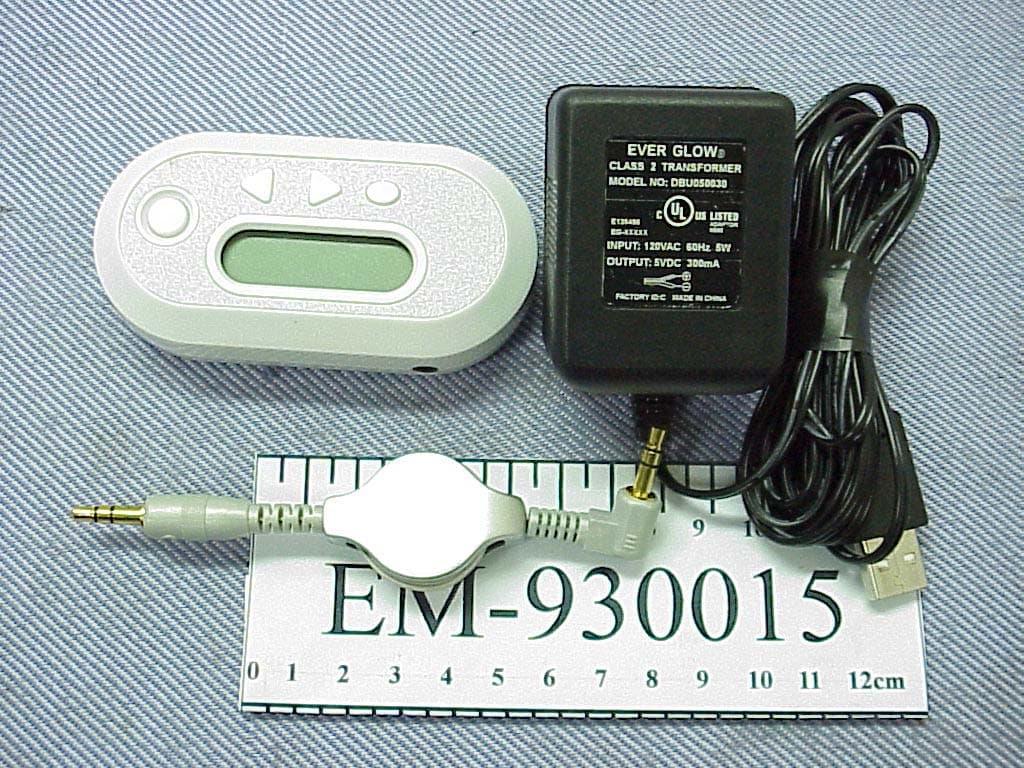
Click to zoom
Application Details
- Equipment Class
- DXX - Part 15 Low Power Communication Device Transmitter
- Date of Grant
- Mar 14, 2004
- Application Purpose
- Original Equipment
- Date of Application
- Mar 14, 2004
- Equipment Note
- Universal Digital FM Transmitter
- Frequency Range
- 88.10000000 - 107.90000000
- Company
- Jow Tong Technology Co.,Ltd
- Country
- Taiwan
Documents & Files
Document Text
Text extracted from the exhibit documents filed with the FCC. Open a document above to read the original.
Users Manual
ST-27 § Universal Digital FM Transmitter § User’s Manual 1 Features: z USB Input Voltage/ Current: DC +5V / 40mA(Max.) z Output RF range: 88.1MHz ~ 107.9MHz z Radio Frequency Adjustment: 0,1MHz / Per step. z Smart/Auto power saving design, with ON/OFF button. z Adjustable audio cable for MP3 & CD players. z Big LCD Digital Display Screen with back light lamp. z Various optional power sources: a. Adaptor [Included] b. USB Connector for personal computer [Optional item] c. Power-supply Holder for car [Included] Contents: Figure 1. 1. Socket for Audio Cable. 2. LCD Digital Display Show out the Radio Frequency. 3. Upper key To increase the radio frequency. 4. Lower key To reduce the radio frequency. 5. Quick key To change the radio frequency faster. 6. Power key Power ON/OFF 2 Installation Instruction : 1. Connect the Digital Transmitter with the adjustable audio cable. See Figure 2. Figure2. 2. Power Supply: a. Adaptor [included] See Figure 3. Figure 3. 3 b. USB Connector for personal computer (Sales separated as optional accessories, not included in the package.) See Figure 4. Figure 4. c. Power-supply Holder for car. Suitable for car with 12V ~ 24V. See Figure 5. Figure 5. When outer power supplied, the LCD Digital Display show on the signal. 4 Adjustment of Radio Frequency Channels: 1. Adjust the radio frequency channels: Radio frequency channels adjustment range is 88.1MHz ~ 107.9MHz. [76MHz ~ 90MHz for Japanese Version] z Press ( Upper key ) / (Lower key ) , to increase/decrease 0,1MHz radio frequency channels of the . z Press ( Upper key ) / (Lower key ) longer, to increase/decrease radio frequency channels before release the button. z Press (Quick key ) to increase/decrease radio frequency channels faster. The radio channels will be adjusted as 88.1 94.0 100.0 106.0 88.1 MHZ . z Power ON/OFF z Press (Power ON/OFF key) to more than one second to turn off the Digital transmitter. Notice of Usage: z This product should be kept in dry condition and avoid of water. z Keep the product off direct sunlight or high temperature environment. z Please unplug the power plug when it’s not in use. z If there are phenomena of defeats, please call your dealer for help. Troubleshooting: If this product doesn’t function normal in used, z Please check whether all wires being connected tight & correct. z If the product cannot be powered on, check whether the power-supply linked well. z If the product has no-other damage, check whether the power of your cigarette lighter is working or not. (When car power-supply holder is used.) z If none of the above phenomena, please call your dealer for help. 6 FCC ID. QPRST27 FEDERAL COMMUNICATIONS COMMISSION INTERFERENCE STATEMENT This equipment has been tested and found to comply with the limits for a Class B digital device, pursuant to Part 15 of the FCC Rules. These limits are designed to provide reasonable protection against harmful interference in a residential installation. This equipment generates, uses and can radiate radio frequency energy and, if not installed and used in accordance with the instructions, may cause harmful interference to radio communications. However, there is no guarantee that interference will not occur in a particular installation. If this equipment does cause harmful interference to radio or television reception, which can be determined by turning the equipment off and on, the user is encouraged to try to correct the interference by one or more of the following measures: • Reorient or relocate the receiving antenna. • Increase the separation between the equipment and receiver. • Connect the equipment into an outlet on a circuit different from that to which the receiver is connected. • Consult the dealer or an experienced radio/TV technician for help. CAUTION: To assure continued FCC compliance: Any changes or modifications not expressly approved by the grantee of this device could void the user's authority to operate the equipment.
Cover Letter(s)
1 Mike Kuo From: leon Sent: March152004Monday 5:15 AM To: Mike Kuo(CCS) Cc: 1Shelene Hou(TTEMC) Subject: Fw: Jow Tong Technology Co., Ltd., FCC ID:QPRST27, AN04T3634 (Update) JowTong-ST27_QP RST27_ID Label ... st27 Universal Digital FM Tran... ST27 Operational Description-1... F930020-JowTong- ST27(0315)-R3.... Hello Mike: There are 4 attached files that we correct the deficiency about ST27; they are: (We already make sure with my client to recognize the correct action) 1. F930020-JowTong-ST27(0313)-R3 Test Report (Revised section 3.7 & Appendix & Frequency range). 2. ST27 Universal Digital Transmitter User Manual-Rev (Revised Frequency) 3. Tong-ST27_QPRST27_ID Label Format (Revised Frequency range) 4. ST27 Operational Decsription-1-r (Revised Frequency range) If any deviations,please let me know ASAP. Best regards.(Hope hear you soon) Leon Liu 3/15 Audix EMC Dept. ----- Original Message ----- From: "Mike Kuo" <[email protected]> To: "'shelene'" ; "Mike Kuo" <[email protected]>; "'cherry'" ; "leon" <leon Sent: Saturday, March 13, 2004 8:57 AM Subject: RE: Jow Tong Technology Co., Ltd., FCC ID:QPRST27, AN04T3634 > Hi Shelene : > > Section 3.7 of test report still show the highest fundamental frequency is > beyond 108MHz, regardless what you have measured in section 4 26dB BW, the > test data still show non-compliance. In addition, page 6 of user manual > indicates the frequencies it tuned to with 0.1MHz increment. You need to > revise all your submitted document to show Exactly Fundamental Frequency > range . Based upon the review history, this device can not declare the > tuning frequency is from 88 - 108MHz. Please review all the document > submitted and provide revised documentation. > > Best Regards > > Mike Kuo > > -----Original Message----- > From: shelene > Sent: Wednesday, March 10, 2004 2:06 AM > To: Mike Kuo; 'cherry'; leon > Subject: Re: Jow Tong Technology Co., Ltd., FCC ID:QPRST27, AN04T3634 > 2 > > Dear Mike : > > For your problem, we informed our customer for your problem and they > modified the control software to meet requirement now, attached please find > our revised report, we re-test Section 4 of report ! > Please check it and let me know if there is any problems now ! if there is > no problem please send me Invoice & Grant letter soon ! thanks. > > I'll send you ST26 revised report by later e-mail, it's same as ST27 > problems ! > > By the way, how about Haicom project ? please let me know the status, > thanks. > > Shelene > ----- Original Message ----- > From: "Mike Kuo" <[email protected]> > To: "'cherry'" ; "Mike Kuo" <[email protected]>; "leon" > > Cc: "TTEMC ) > Sent: Thursday, March 04, 2004 9:06 AM > Subject: RE: Jow Tong Technology Co., Ltd., FCC ID:QPRST27, AN04T3634 > > > Hi Cherry : > > If the USB connector for PC is only to supply power from PC to EUT, then it > does not consider as PC peripheral device per section 15.3(r) of FCC rules. > In this case, FCC DoC procedure does not apply. > > In the attached test report, the test data still does not comply with > Question #5. This device is operated under section 15.239 of FCC rules. > The frequency band for 15.239 is designed for the fundamental frequency band > from 88 -1 08MHz. In the revised test report, the lower channel of > fundamental is tuned to 88.0667MHz and the high channel of fundamental is > tuned to 108.84MHz which are outside of frequency band. 108.84MHz is > restricted band per 15.205 table. No fundamental frequency can transmit in > the restricted band. > > In addition, the 200kHz does not contains within the band. Please address > these non-compliance issues. > > When you reply to the questions, please address each question and provide > the method was used to address the questions. In the original test report, > the test data submitted do not comply with 15.21(b) as indicated in the > question #2, but the revised test report do comply with 15.21(b) but no > explanation was given. What have been done to correct the spurious > emissions since there is no modification made on the device ? > > Best Regards > > Mike Kuo 3 > > -----Original Message----- > From: cherry > Sent: Monday, March 01, 2004 3:37 AM > To: TCB- Mr.Mike; leon > Cc: TTEMC (Shelene_Hou) > Subject: Re: Jow Tong Technology Co., Ltd., FCC ID:QPRST27, AN04T3634 > Importance: High > > > Dear Mike, > > Attached files are the revised test report for your question. > > For Question # 3, the USB connector for PC is only the one method of power > supply, no others function! > we don't think it belong to PC peripheral ! If only the power supply > function, do we need to compliance with Part 15B? > > Should your have any comments, please let me know. Thanks for your > cooperation! > > Cherry Wang > AUDIX Corporation, EMC Dept. > > This e-mail and the information it contains may be legally privileged > and/orCONFIDENTIAL. The unauthorised use, disclosure, distribution and/or > copying > of this e-mail,or any information it contains, is prohibited and could, in > certaincircumstances, constitute a criminal offence. If you are not an > intended recipient > please inform the senderby selecting the reply button to return e-mail > and/or telephone +886-2-26092133. E-mail may be susceptible to data > corruption, > interceptionand unauthorised amendment,and we do not accept liability for > any such corruption, interception oramendment or the consequences thereof. > > > > ----- Original Message ----- > From: "leon" > To: "1Ben Cheng" > Cc: <> > Sent: Thursday, February 19, 2004 6:30 AM > Subject: Re: Jow Tong Technology Co., Ltd., FCC ID:QPRST27, AN04T3634 > > > > Dear Ben: 4 5
External Photos
Page 4 Jow Tong Technology Co., Ltd. Universal Digital FM Transmitter FCC ID. : QPRST27 Photographs of EUT (External & Internal) Photos 1 Appearance View (Universal Digital FM Transmitter 、 AC Adapter 、 Audio Cable) Photos 2 Appearance View (Universal Digital FM Transmitter 、 Power-Supply Holder for Car) Page 5 Jow Tong Technology Co., Ltd. Universal Digital FM Transmitter FCC ID. : QPRST27 Photos 3 (Universal Digital FM Transmitter) Appearance View Photos 4 (Universal Digital FM Transmitter) Appearance View Page 6 Jow Tong Technology Co., Ltd. Universal Digital FM Transmitter FCC ID. : QPRST27 Photos 5 (Power-Supply Holder for Car) Appearance View Photos 6 (Power-Supply Holder for Car) Appearance View Page 7 Jow Tong Technology Co., Ltd. Universal Digital FM Transmitter FCC ID. : QPRST27 Photos 7 (AC Adapter) Appearance View Photos 8 (AC Adapter) Appearance View
ID Label/Location Info
Page 17 Jow Tong Technology Co., Ltd. Universal Digital FM Transmitter FCC ID. : QPRST27 ID Label Format and Location z Label Format Model: ST-27 I/P: DC5V/40mA(Max.) Frequency: 88.1MHz~107.9MHz FCC ID: QPRST27 MADE IN TAIWAN z Label Placement Location (Bottom Side of EUT) FCC Label Placement Location
Internal Photos
Page 8 Jow Tong Technology Co., Ltd. Universal Digital FM Transmitter FCC ID. : QPRST27 Photos 9 (Universal Digital FM Transmitter) Remove Case Covers, Internal View Photos 10 (Universal Digital FM Transmitter) Main Board & TX Control Board View Page 9 Jow Tong Technology Co., Ltd. Universal Digital FM Transmitter FCC ID. : QPRST27 Photos 11 (Universal Digital FM Transmitter) Main Board, Back Side Photos 12 (Universal Digital FM Transmitter) Main Board, Front Side Page 10 Jow Tong Technology Co., Ltd. Universal Digital FM Transmitter FCC ID. : QPRST27 Photos 13 (Universal Digital FM Transmitter) TX Control Board, Component Side Photos 14 (Universal Digital FM Transmitter) TX Control Board, Solder Side Page 11 Jow Tong Technology Co., Ltd. Universal Digital FM Transmitter FCC ID. : QPRST27 Photos 15 (Power-Supply Holder for Car) Remove Case Cover, Internal View Photos 16 (Power-Supply Holder for Car) Remove Case Cover, Internal View Page 12 Jow Tong Technology Co., Ltd. Universal Digital FM Transmitter FCC ID. : QPRST27 Photos 17 (Power-Supply Holder for Car) PCB View, Component Side Photos 18 (Power-Supply Holder for Car) PCB View, Solder Side Page 13 Jow Tong Technology Co., Ltd. Universal Digital FM Transmitter FCC ID. : QPRST27 Photos 19 (AC Adapter) Remove Case Covers, Internal View Photos 20 (AC Adapter) Transformer & PCB View, Front Side Page 14 Jow Tong Technology Co., Ltd. Universal Digital FM Transmitter FCC ID. : QPRST27 Photos 21 (AC Adapter) Transformer & PCB View, Back Side
Test Report
FCC ID.QPRST27 Page 1 of 50 (REVISED VERSION) TEST REPORT FOR CERTIFICATION On Behalf of Jow Tong Technology Co., Ltd. Universal Digital FM Transmitter Model No.:ST-27 FCC ID:QPRST27 Prepared for : Jow Tong Technology Co., Ltd. 46, Lane 337, Chung Cheng Rd., Yung Kang, Tainan Hsien 710, Taiwan, R.O.C. Prepared by : Audix Corporation Technical Division EMC Department No. 53-11, Tin-Fu Tsun, Lin-Kou, Taipei Hsien, Taiwan, R.O.C. Tel : (02) 2609-9301, 2609-2133 Fax: (02) 2609-9303 File Number : EM930015 Report Number : EM-F930020 Date of Test : Feb. 09 ~ Mar. 13, 2004 (Rev. 3) Date of Report : Mar. 15, 2004 Audix Corporation Report No. EM-F930020 FCC ID.QPRST27 Page 2 of 50 TABLE OF CONTENTS Description Page TEST REPORT CERTIFICATION.......................................................................................................3 1. GENERAL INFORMATION.........................................................................................................4 1.1. Description of Device (EUT)..................................................................................................................4 1.2. Tested Supporting System Details..........................................................................................................5 1.3. Description of Test Facility ....................................................................................................................6 1.4. Measurement Uncertainty.......................................................................................................................6 2. POWERLINE CONDUCTED EMISSION MEASUREMENT..................................................7 2.1. Test Equipment.......................................................................................................................................7 2.2. Block Diagram of Test Setup..................................................................................................................7 2.3. Conducted Limits (Comply with §15.207).............................................................................................8 2.4. EUT’s Configuration during Compliance Measurement........................................................................8 2.5. Operating Condition of EUT ..................................................................................................................8 2.6. Test Procedure........................................................................................................................................9 2.7. Conducted Emission Measurement Results..........................................................................................10 3. RADIATED EMISSION MEASUREMENT..............................................................................16 3.1. Test Equipment.....................................................................................................................................16 3.2. Test Setup.............................................................................................................................................16 3.3. Radiation Limit (Comply with §15.239 & §15.209)............................................................................17 3.4. EUT’s Configuration during Compliance Measurement......................................................................18 3.5. Operating Condition of EUT ................................................................................................................19 3.6. Test Procedure......................................................................................................................................19 3.7. Radiated Emission Noise Measurement Results...................................................................................20 4. 26dB BANDWIDTH MEASUREMENT.....................................................................................24 4.1. Test Equipment.....................................................................................................................................24 4.2. Block Diagram of Test Setup................................................................................................................24 4.3. Specification Limits (§15.239).............................................................................................................24 4.4. EUT’s Configuration during Compliance Measurement......................................................................24 4.5. 26dB Bandwidth Measurement Results................................................................................................ 24 5. DEVIATION TO TEST SPECIFICATIONS..............................................................................28 6. PHOTOGRAPHS...........................................................................................................................29 6.1. Photos of Conducted Measurement ......................................................................................................29 6.2. Photos of Radiated Measurement at Semi-Anechoic Chamber (30-1000MHz)...................................31 6.3. Photos of Radiated Measurement at Semi-Anechoic Chamber (1-2GHz)...........................................34 6.4. Photos of Bandwidth Measurement ......................................................................................................37 APPENDIX (Radiated Test data At Semi-Anechoic Chamber)...........................................................38 Audix Corporation Report No. EM-F930020 FCC ID.QPRST27 Page 3 of 50 TEST REPORT CERTIFICATION Applicant : Jow Tong Technology Co., Ltd. Manufacturer : Jow Tong Technology Co., Ltd. EUT Description : Universal Digital FM Transmitter FCC ID : QPRST27 (A) MODEL NO. : ST-27 (B) SERIAL NO. : N/A (C) POWER SUPPLY:DC +5V/40mA Measurement Procedure Used: FCC RULES AND REGULATIONS PART 15 SUBPART C, DEC. 2003 AND ANSI C63.4-2001 (FCC CFR 47 Part 15C, §15.203, §15.207, §15.209 and §15.239) The d…
Text truncated - open the document above for the full version.
Test Setup Photos
FCC ID.QPRST27 Page 25 of 45 6. PHOTOGRAPHS 6.1. Photos of Conducted Measurement FRONT VIEW OF CONDUCTED MEASUREMENT BACK VIEW OF CONDUCTED MEASUREMENT Audix Corporation Report No. EM-F930020 FCC ID.QPRST27 Page 26 of 45 6.2. Photos of Radiated Measurement at Semi-Anechoic Chamber (30-1000MHz) Test Mode: EUT’ s Power Supply with AC Adapter (AC 120V/60Hz) FRONT VIEW OF RADIATED MEASUREMENT BACK VIEW OF RADIATED MEASUREMENT Audix Corporation Report No. EM-F930020 FCC ID.QPRST27 Page 27 of 45 EUT’ s Power Supply with Power-Supply Holder for Car (DC 12V) FRONT VIEW OF RADIATED MEASUREMENT BACK VIEW OF RADIATED MEASUREMENT Audix Corporation Report No. EM-F930020 FCC ID.QPRST27 Page 28 of 45 6.3. Photos of Radiated Measurement at Semi-Anechoic Chamber (1-2GHz) Test Mode: EUT’ s Power Supply with AC Adapter (AC 120V/60Hz) FRONT VIEW OF RADIATED MEASUREMENT BACK VIEW OF RADIATED MEASUREMENT Audix Corporation Report No. EM-F930020 FCC ID.QPRST27 Page 29 of 45 EUT’ s Power Supply with Power-Supply Holder for Car (DC 12V) FRONT VIEW OF RADIATED MEASUREMENT BACK VIEW OF RADIATED MEASUREMENT Audix Corporation Report No. EM-F930020 FCC ID.QPRST27 Page 30 of 45 6.4. Photos of Bandwidth Measurement Audix Corporation Report No. EM-F930020
Contact Information
Applicant
Shen-Fu Shu(Manager)
Test Firm
Audix Technology CorporationJeff Chen
Technical Specifications
| # | Rule Parts | Frequency Range | Power Output |
|---|---|---|---|
| 1 | 15C | 88.1 MHz - 107.9 MHz | - |
Other Applications from Jow Tong Technology Co.,Ltd
QPR-XT-2605
Mar 20, 2007Airplay
Equipment Class
DXX - Part 15 Low Power Communication Device Transmitter
QPRDL-14
Mar 02, 2006nano TUNE
Equipment Class
DXX - Part 15 Low Power Communication Device Transmitter
QPRDL18
Aug 24, 2005TransPod2
Equipment Class
DXX - Part 15 Low Power Communication Device Transmitter
QPRST30
Oct 04, 2004Universal Digital FM Transmitter
Equipment Class
DXX - Part 15 Low Power Communication Device Transmitter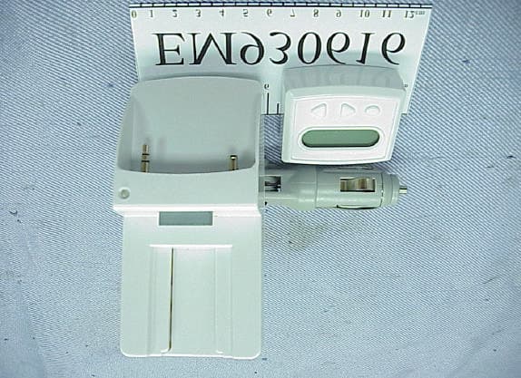
QPRST31
Jul 06, 2004Digital FM Transmitter
Equipment Class
DXX - Part 15 Low Power Communication Device Transmitter