QPS01001DISTRIBUTED SERIES REACTANCE
Smart Wires, Inc.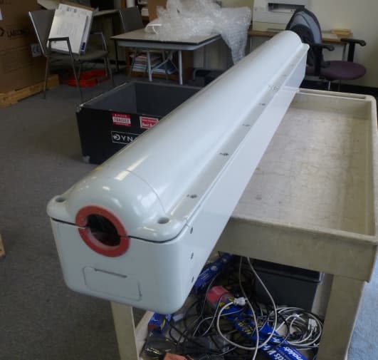
Click to zoom
Application Details
- Equipment Class
- DXX - Part 15 Low Power Communication Device Transmitter
- Date of Grant
- Feb 28, 2013
- Application Purpose
- Original Equipment
- Date of Application
- Feb 28, 2013
- Equipment Note
- DISTRIBUTED SERIES REACTANCE
- Frequency Range
- 902.00000000 - 928.00000000
- Company
- Smart Wires, Inc.
- Country
- United States
Documents & Files
Document Text
Text extracted from the exhibit documents filed with the FCC. Open a document above to read the original.
Users Manual
Copyright 2012 Smart Wire Grid, Inc. All Rights Reserved DSR User Manual General Description: The DSR or “Distributed Series Reactance” is a critical part of the Smart Wire Grid system to assist utilities and other industrial customers with retrofitting existing power line infrastructure and allow power flow control for the grid. The DSR is the workhorse of the system which is mounted on the power line and controlled through the RF link to enable and disable the control system of the DSR and provide telemetry back to the base station. Installation: The DSR is typically installed on a high-tension power line by first shutting down the power line, attaching the DSR, and then returning power to the line. The DSR mounts to the power line by placing the bottom housing underneath the line then capturing the power line with the top housing, then bolting the two housings together to clamp onto the power line. Once bolted together, the DSR is ready for use. Operation: The DSR turns on automatically when the power line is powered on. Once powered on, the DSR communicates to a base station using the RF link. The RF link is then used to turn the control system of the DSR on and off to allow for smart power flow control for the grid. In addition to enabling and disabling the features of the DSR, the radio link communicates the current status of the DSR to the base station. Lifespan & Service: The DSR unit is designed to withstand a 20 year installation life. In the event of malfunction, the DSR may remain on the power line until the next service interval. DSR units may be serviced by removing them from the power line and replacing the unit.
Cover Letter(s)
Smart Wire Grid, Inc. 1300 Clay Street, Ste. 840 Oakland, CA 94612-1428 T. 510-267-4320, F. 510-267-4322 www.SmartWireGrid.com The information and methodologies outlined herein are proprietary, trade secret, and their expression in this document is copyrighted, with all rights reserved to Smart Wire Grid, Inc. Copying or distributing this material without prior written permission is strictly prohibited. March 18, 2013 Attention: Application Examiner Re: Request for confidentiality Applicant: Smart Wire Grid, Inc. FCC ID: QPS01001 To whom it may concern, Request is hereby submitted by Smart Wire Grid, Inc. to withhold permanently from public review certain portions of the application for equipment certification for the referenced FCC identifiers. This request for confidentiality is made pursuant to 47 CFR 0.457(d) and 0.459 of the FCC Rules. In particular, the following sections of the application are to be kept permanently confidential: • Schematics • Detailed Block diagrams • Detailed Operational/Functional Description • Internal photographs Rationale for request for confidentiality: Smart Wire Grid, Inc. has invested considerable time and materials in research and development to produce the referenced product. Disclosure of the permanently confidential portions of this application to competitors would not only give them significant competitive advantages in developing similar products, but would also disclose successful implementation of unpublished, leading edge technology developed by us. The attached blank NDA between Smart Wire Grid and prospective purchaser demonstrates the level of confidentiality required. The product, by the nature of its intended use, is not accessible by general public and/or non-authorized personnel. This request supersedes the Request for Confidentiality submitted by SWG on December 3, 2012 If you have questions or need further information, please contact the undersigned. Thank you. Sincerely, Julie A. Couillard VP Engineering and Customer Support Smart Wire Grid, Inc.
Cover Letter(s)
Nondisclosure Agreement – Smart Wire Grid, Inc. 1 NONDISCLOSURE AGREEMENT THIS AGREEMENT, made effective as of the __ day of __________, 20__ by and between Smart Wire Grid, Inc. (hereinafter “Company”) and ___________________ (hereinafter the "Purchaser"), to assure the protection and preservation of the confidential and/or proprietary nature of information to be disclosed or made available by Company to the Purchaser in connection with certain negotiations or discussions further described in Exhibit A attached hereto. WHEREAS, the parties desire to assure the confidential status of the information which may be disclosed by Company to the Purchaser; NOW THEREFORE, in reliance upon and in consideration of the following undertakings, the parties agree as follows: 1. Subject to the limitations set forth in Paragraph 2, all information disclosed by Company to the Purchaser shall be deemed to be "Proprietary Information." In particular, Proprietary Information shall be deemed to include any trade secret, information, process, technique, algorithm, computer program (source and object codes), design, drawing, formula, test data, relating to any work in process, future development, marketing, servicing, financing or personnel matter relating to Company, its present or future products, sales, suppliers, clients, employees, investors, or business, whether in oral, written, graphic or electronic form. 2. The term "Proprietary Information" shall not be deemed to include information which the Purchaser can demonstrate by competent written proof: (i) is now, or hereafter becomes, through no act or failure to act on the part of the Purchaser, generally known or available; (ii) is known by the Purchaser at the time of receiving such information as evidenced by its records; (iii) is hereafter furnished to the Purchaser by a third party, as a matter of right and without restriction on disclosure; or (iv) is the subject of a written permission to disclose provided by Company. 3. The Purchaser shall maintain in trust and confidence and not disclose to any third party or use for any unauthorized purpose any Proprietary Information received from Company. The Purchaser may use such Proprietary Information only to the extent required to accomplish the intent of this Agreement. The Purchaser shall not use Proprietary Information for any purpose or in any manner that would constitute a violation of any laws or regulations, including without limitation the export control laws of the United States. No other rights or licenses to trademarks, inventions, copyrights, or patents are implied or granted under this Agreement. 4. Proprietary Information supplied shall not be reproduced in any form except as required to accomplish the intent of this Agreement. 5. The Purchaser represents and warrants that it shall protect the Proprietary Information received with at least the same degree of care used to protect its own Proprietary Information from unauthorized use or disclosure. The Purchaser shall advise its employees or Nondisclosure Agreement – Smart Wire Grid, Inc. 2 agents who might have access to such Proprietary Information of the confidential nature thereof and shall obtain from each of such employees and agents an agreement to abide by the terms of this Agreement. The Purchaser shall not disclose any Proprietary Information to any officer, employee or agent who does not have a need for such information. 6. All Proprietary Information (including all copies thereof) shall remain the property of Company, and shall be returned to Company after the Purchaser's need for it has expired, or upon request of Company, and in any event, upon completion or termination of this Agreement. 7. Notwithstanding any other provision of this Agreement, disclosure of Proprietary Information shall not be precluded if such disclosure: a. is in response to a valid order of a court or other governmental body of the United States or any political subdivision thereof; provided, however, that the Purchaser shall promptly give notice to Company of such order in order to allow Company the opportunity to obtain a protective order or other appropriate remedy; b. is otherwise required by law; or c. is otherwise necessary to establish rights or enforce obligations under this Agreement, but only to the extent that any such disclosure is necessary. 8. This Agreement shall continue in full force and effect for so long as the Purchaser continues to receive Proprietary Information. This Agreement may be terminated at any time upon thirty (30) days written notice to the other party. The termination of this Agreement shall not relieve the Purchaser of the obligations imposed by Paragraphs 3, 4, 5, 6 and 12 of this Agreement with respect to Proprietary Information disclosed prior to the effective date of such termination and the provisions of these Paragraphs shall survive the termination of this Agreement for a period of three (3) years from the date of such termination; provided, however, that with respect to trade secrets, the provisions of these Paragraphs shall survive the termination of this Agreement until the information subject to it is lawfully placed in the public domain. For purposes of this Paragraph, “trade secrets” shall be deemed to be Proprietary Information in the process of being patented or copyrighted or trademarked or which has explicitly been disclosed in writing by the disclosing party as a “trade secret”. 9. The Purchaser agrees to indemnify Company for any loss or damage suffered as a result of any breach by the Purchaser of the terms of this Agreement, including any reasonable fees incurred by Company in the collection of such indemnity. 10. This Agreement shall be governed by the laws of the State of California as those laws are applied to contracts entered into and to be performed entirely in California by California residents. Nondisclosure Agreement – Smart Wire Grid, Inc. 3 11. This Agreement contains the final, complete and …
Text truncated - open the document above for the full version.
External Photos
Illustrate unit with securing screws removed. Illustrate unit with securing screws removed. Illustrate unit with securing screws removed. Illustrate unit with securing screws removed.
Test Report
RF Emissions Test Report To Determine Compliance With: FCC, Part 15.249 Rules and Regulations Model number: DSR-750b Date: January 23, 2013 Manufacturer: Smart Wire Grid, Inc. 1300 Clay Street, Ste 840 Oakland, CA 94612-1428 EMC Testing Laboratories, Inc. authorizes the above company to reproduce this report provided it is reproduced in its entirety EMC Tests, Inc. (770) 475-8819 Test report no. 12-215A Page 2 of 40 Contents Section General Information -------------------------------------------------------- 1 Product Description and Test Summary --------------------------------- 2 Standard Reference --------------------------------------------------------- 3 Test Method ----------------------------------------------------------------- 4 Output Power --------------------------------------------------------------- 5 Bandwidth ------------------------------------------------------------------ 6 Configuration -------------------------------------------------------------- 7 Block Diagram ------------------------------------------------------------- 8 Circuit Schematics, Range Extender ------------------------------------ 9 Circuit Schematics, Transceiver ----------------------------------------- 10 Photographs ----------------------------------------------------------------- 11 FCC Label ------------------------------------------------------------------- 12 FCC Label Location -------------------------------------------------------- 13 Test Equipment ------------------------------------------------------------ 14 EMC Tests, Inc. (770) 475-8819 Test report no. 12-215A Page 3 of 40 Section 1 GENERAL INFORMATION Manufacturer: Smart Wire Grid, Inc. 1300 Clay Street, Ste 840 Oakland, CA 94612 Manufacturer representative: Ms. Julie Couillard Equipment covered by this report: Model no. DSR-750b Equipment serial number: 1231A001 Options covered by this report: None Transmitting Frequency: 902 - 928 MHz Test specifications: To determine compliance with: FCC, Part 15.249, Subpart B and C, Rules and Regulations, Class B. Test report number: 12-215A FCC ID QPS01001 Test commenced: November 27, 2012 Test completed: February 22, 2013 Test engineer: Glenn Barnes Test Facility: The test facility used to perform these tests is on file with the FCC under registration number 637500 and IC no. 3519A and located at: EMC Testing Laboratories, Inc. 2100 Brandon Trail Suite 101 Alpharetta, GA 30004 770-475-8819 EMC Tests, Inc. (770) 475-8819 Test report no. 12-215A Page 4 of 40 Section 2 PRODUCT DESCRIPTION AND TEST SUMMARY Product description: The product is an industrial device that is designed to be hanged on the high-voltage transmission lines. The device contains microcontroller and two identical 0.5W 915MHz ISM band transceiver. The unit starts RF transmission automatically when powered up and has no operator controls. Normally, the device is powered by the transmission line current – up to 1000A, but for testing purpose it will be equipped with a rechargeable battery placed inside the unit. The two low-gain, cavity-backed slot antennas are located at the ends of the device. Each antenna is connected to its own transceiver. As the transceivers and the antennas are equal and are not intended to be transmitting at the same time, testing just one channel should be sufficient. The integral antenna is a cavity-backed slot antenna. The test results apply only to the products identified on this test report. Test program: The product was tested in accordance with 15.249. This product is exempt from the 15.209 Radiated emissions tests in accordance with paragraph 15.103 b and c. Test configuration: The equipment under test (EUT) was set-up and configured as specified by the manufacturer as follows: 1- The product was connected to the following support peripherals: A. Laptop to program output frequency. 2- The product utilized the following cables and were connected as indicated below: A- None Modifications: The following modifications were required to comply with the radiated emission limits: 1- None EMC Tests, Inc. (770) 475-8819 Test report no. 12-215A Page 5 of 40 Product Description and Test Summary ... Engineering Statement: All measurement data of this test report was taken in accordance with the FCC, Part 15.249, Class B Rules and Regulations and ANSI C63.4 (09) by EMC Testing Laboratories, Inc. located in Alpharetta, Georgia. Although this data is taken under stringent laboratory conditions and to the best of our knowledge, represents accurate data, it must be recognized that emissions from or immunity to this type equipment may be greatly affected by the final installation of the equipment. Therefore, EMC Testing Laboratories, Inc., while supporting the accuracy of the data in this report, takes no responsibility for use of equipment based on these tests. The manufacturer of this equipment must take full responsibility for any field problems which may arise, and agrees that EMC Testing Laboratories, Inc., in performing its functions in accordance with its objectives and purposes, does not assume or undertake to discharge any responsibility of the manufacturer to any other party or parties. Conclusion: With the above-indicated modifications, the product covered by this report has been tested and found to comply with the above-indicated standards. Tested by: Glenn Barnes, RF Engineer Approved by: Gene Bailey Gene BaileyGene Bailey Gene Bailey Gene Bailey, Engineering Manager EMC Test Laboratories, Inc. EMC Tests, Inc. (770) 475-8819 Test report no. 12-215A Page 6 of 40 Section 3 STANDARD REFERENCE The following primary standards were used for this test: 1- ANSI C63.4 (09): Method of Measurements of Radio-Noise Emissions from Low-Voltage Electrical and Electronic Equipment in the 9 KHz to 40 GHz. 2- US Code of Federal Regulations (CFR): Title 47, Part 15, Radio Frequency Devices, Subpart B, Intentional Radiators. Note: Applicable amendments were applied to all standards. EMC Tests, Inc. (770) 475-8819 Test report…
Text truncated - open the document above for the full version.
Test Setup Photos
Section 11 PHOTOGRAPHS Photographs cont... Radiated Emissions Measurements Photographs cont... Radiated Emissions Measurements
Contact Information
Applicant
Karamjit Singh
Test Firm
EMC Testing Laboratories, Inc.Gene Bailey
Technical Specifications
| # | Rule Parts | Frequency Range | Power Output |
|---|---|---|---|
| 1 | 15C | 902 MHz - 928 MHz | - |
Other Applications from Smart Wires, Inc.
QPS01009
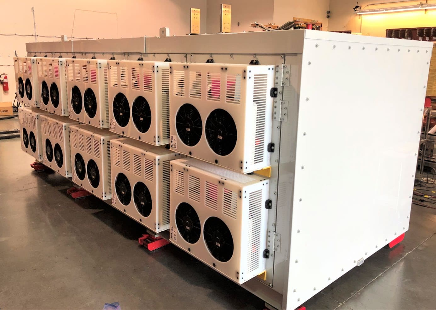
Feb 08, 2021SmartValve with Integrated Bypass
Equipment Class
DSS - Part 15 Spread Spectrum Transmitter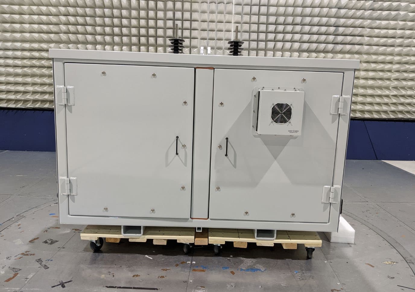
QPS01008
Jan 17, 2020SmartBypass
Equipment Class
DSS - Part 15 Spread Spectrum Transmitter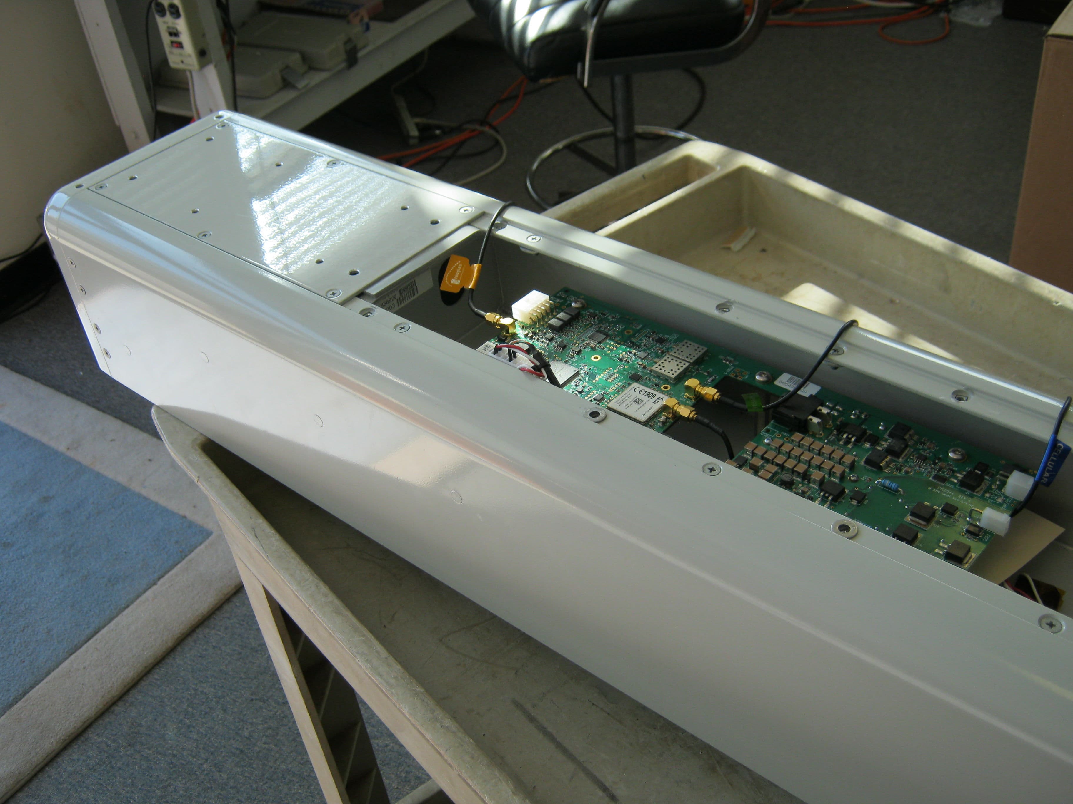
QPS01002
Dec 08, 2014Line monitor
Equipment Class
DSS - Part 15 Spread Spectrum Transmitter