QPS01002Line monitor
Smart Wires, Inc.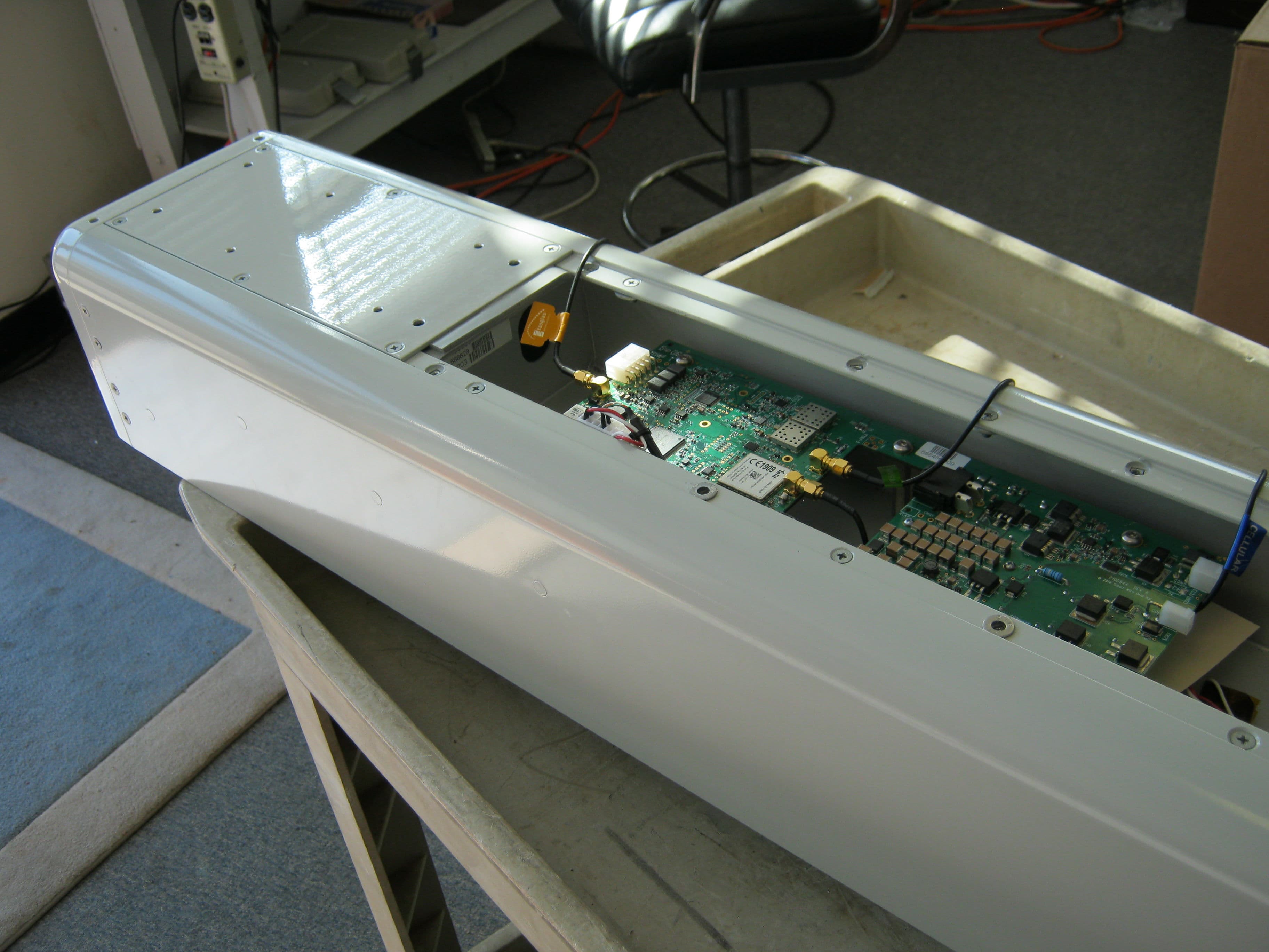
Click to zoom
Application Details
- Equipment Class
- DSS - Part 15 Spread Spectrum Transmitter
- Date of Grant
- Dec 08, 2014
- Application Purpose
- Original Equipment
- Date of Application
- Dec 08, 2014
- Equipment Note
- Line monitor
- Frequency Range
- 903.00000000 - 927.00000000
- Company
- Smart Wires, Inc.
- Country
- United States
Documents & Files
Document Text
Text extracted from the exhibit documents filed with the FCC. Open a document above to read the original.
Users Manual
Copyright 2014 Smart Wire Grid, Inc. All Rights Reserved PowerLine Guardian User Manual General Description: The PowerLine Guardian (PLG) is a critical part of the Smart Wire Grid system to assist utilities and other industrial customers with retrofitting existing power line infrastructure and allow power flow control for the grid. The PLG is the workhorse of the system which is mounted on the power line and controlled through the RF link to enable and disable the control system of the PLG and provide telemetry back to the base station. Installation: The PowerLine Guardian is typically installed on a high-tension power line by first shutting down the power line, attaching the PLG, and then returning power to the line. The PLG mounts to the power line by placing the bottom housing underneath the line then capturing the power line with the top housing, then bolting the two housings together to clamp onto the power line. Once bolted together, the PLG is ready for use. Operation: The PowerLine Guardian turns on automatically when the power line is powered on. Once powered on, the PLG communicates to a base station using the RF link which utilized 915MHz band or 868MHz band depending on the local regulations. The RF link is then used to turn the control system of the PLG on and off to allow for smart power flow control for the grid. In addition to enabling and disabling the features of the PLG, the radio link communicates the current status of the PLG to the base station. The PowerLine Guardian is equipped with an optional cellular modem that may utilize the cellular service available in the area. Lifespan & Service: The PLG unit is designed to withstand a 20 year operational life. In the event of malfunction, the PLG may remain on the power line until the next service interval. A PLG unit may be serviced by removing it from the power line and returning the unit to the factory. There are no field serviceable parts inside. Copyright 2014 Smart Wire Grid, Inc. All Rights Reserved Legal Disclaimers: A. THIS DEVICE COMPLIES WITH PART 15 OF THE FCC RULES. OPERATION IS SUBJECT TO THE FOLLOWING TWO CONDITIONS: (1) THIS DEVICE MAY NOT CAUSE HARMFUL INTERFERENCE, AND (2) THIS DEVICE MUST ACCEPT ANY INTERFERENCE RECEIVED, INCLUDING INTERFERENCE THAT MAY CAUSE UNDESIRED OPERATION. B. NOTE: THE MANUFACTURER IS NOT RESPONSIBLE FOR ANY RADIO OR TV INTERFERENCE CAUSED BY UNAUTHORIZED MODIFICATIONS TO THIS EQUIPMENT. SUCH MODIFICATIONS COULD VOID THE USER’S AUTHORITY TO OPERATE THE EQUIPMENT.
Users Manual
Copyright 2014 Smart Wire Grid, Inc. All Rights Reserved PowerLine Guardian User Manual General Description: The PowerLine Guardian (PLG) is a critical part of the Smart Wire Grid system to assist utilities and other industrial customers with retrofitting existing power line infrastructure and allow power flow control for the grid. The PLG is the workhorse of the system which is mounted on the power line and controlled through the RF link to enable and disable the control system of the PLG and provide telemetry back to the base station. Installation: The PowerLine Guardian is typically installed on a high-tension power line by first shutting down the power line, attaching the PLG, and then returning power to the line. The PLG mounts to the power line by placing the bottom housing underneath the line then capturing the power line with the top housing, then bolting the two housings together to clamp onto the power line. Once bolted together, the PLG is ready for use. Operation: The PowerLine Guardian turns on automatically when the power line is powered on. Once powered on, the PLG communicates to a base station using the RF link which utilized 915MHz band or 868MHz band depending on the local regulations. The RF link is then used to turn the control system of the PLG on and off to allow for smart power flow control for the grid. In addition to enabling and disabling the features of the PLG, the radio link communicates the current status of the PLG to the base station. The PowerLine Guardian is equipped with an optional cellular modem that may utilize the cellular service available in the area. Lifespan & Service: The PLG unit is designed to withstand a 20 year operational life. In the event of malfunction, the PLG may remain on the power line until the next service interval. A PLG unit may be serviced by removing it from the power line and returning the unit to the factory. There are no field serviceable parts inside.
Cover Letter(s)
_____________________________________________________________________________________ Smart Wire Grid, Inc. • 1300 Clay Street, Suite 840 • Oakland, CA 94612 • T: (510) 267-4334 F: (510) 267-4322 September 19, 2014 Attention: Application Examiner Re: Request for confidentiality Applicant: Smart Wire Grid, Inc. FCC ID: QPS01002 To whom it may concern, Request is hereby submitted by Smart Wire Grid, Inc. to withhold permanently from public review certain portions of the application for equipment certification for the referenced FCC identifiers. This request for confidentiality is made pursuant to 47 CFR 0.457(d) and 0.459 of the FCC Rules. In particular, the following sections of the application are to be kept permanently confidential: Schematics Detailed Block diagrams Detailed Operational/Functional Description Rationale for request for confidentiality: Smart Wire Grid, Inc. has invested considerable time and materials in research and development to produce the referenced product. Disclosure of the permanently confidential portions of this application to competitors would not only give them significant competitive advantages in developing similar products, but would also disclose successful implementation of unpublished, leading edge technology developed by us. If you have questions or need further information, please contact the undersigned. Thank you. Sincerely, Julie A. Couillard VP Engineering and Customer Support
External Photos
Photographs cont... Illustrates Complete Product, Bottom Side Photographs cont... Illustrates Complete Product, Bottom Top side Photographs cont... Illustrates Complete Product, With Top Cover Removed Photographs cont... Illustrates Complete Product, With Cover Over Board is Removed
ID Label/Location Info
Model: PowerLine Guardian™ 1000 U.S Patent No. 7,835,128 and patents pending Smart Wire Grid, Inc. 1300 Clay Street, Suite 840 Oakland, CA 94612 USA Power Line FCC ID: QPS01002 Contains FCC ID: RI7HE910NAV2 11 1 111 Mfg Location: Wilmington, NC USA Approximate Weight: 211 lbs Winding Material: Copper Core Material: Steel Basic Insulation Level: 550 kV Mfg Date: September 17, 2014 Max Continuous Current: 1000 A RMS Max Operating Voltage: 123 kV RMS Inductance @ 1000 A: 42 μH ± 5% Max Fault Current: 63 kA RMS Max Continuous Conductor Temp: 100° C Frequency: 60 Hz Serial No: 26014-001-10-02A-0D PowerLine Guardian™ Connection Diagram: 26014-001-10-02A-0D THIS DEVICE COMPLIES WITH PART 15 OF THE FCC RULES, OPERATION IS SUBJECT TO THE FOLLOWING TWO CONDITIONS: (1) THIS DEVICE MAY NOT CAUSE HARMFUL INTERFERENCE, AND (2) THIS DEVICE MUST ACCEPT ANY INTERFERENCE RECEIVED, INCLUDING INTERFERENCE THAT MAY CAUSE UNDESIRED OPERATION.
Internal Photos
Photographs cont... Main Board with Radio Photographs cont... Other View of Main Board Photographs cont... Main Board with Shields Removed Photographs cont... Main Board Photographs cont... Main Board Photographs cont... Main Board Photographs cont... Main Board
Test Report
RF Emissions Test Report To Determine Compliance With: FCC, Part 15, Subpart B and C Rules and Regulations Model number: PowerLine Guardian. FCC ID: QPS01002 Date: October 29, 2014 Manufacturer: Smart Wire Grid, Inc. 1300 Clay Street, Suite 840 Oakland, CA 94612 EMC Testing Laboratories, Inc. authorizes the above company to reproduce this report provided it is reproduced in its entirety EMC Testing Laboratories, Inc. Test report no 14-193A Page 2 of 62 Contents Section General Information -------------------------------------------------------- 1 Test Summary --------------------------------------------------------------- 2 Standard Reference --------------------------------------------------------- 3 20 dB Bandwidth ----------------------------------------------------------- 4 Carrier Frequency Separation --------------------------------------------- 5 Number of Hopping Frequencies ----------------------------------------- 6 Time of Occupancy --------------------------------------------------------- 7 Peak Output Power --------------------------------------------------------- 8 Band-Edge Compliance of rf Conducted Emissions ------------------ 9 Spurious rf Conducted Emissions --------------------------------------- 10 Spurious Radiated Emissions -------------------------------------------- 11 Radiated Emissions Measurements ------------------------------------- 12 Photographs ---------------------------------------------------------------- 13 Test Equipment ------------------------------------------------------------ 14 EMC Testing Laboratories, Inc. Test report no 14-193A Page 3 of 62 Section 1 GENERAL INFORMATION Manufacturer: Smart Wire Grid, Inc. 1300 Clay Street, Suite 840 Oakland, CA 94612 Manufacturer representative: Ms. Julie Couillard Equipment covered by this report: Model no. PowerLine Guardian Options covered by this report: None Equipment serial no. Prototype Test specifications: To determine compliance with: FCC, Part 15, Subpart B and C, Rules and Regulations, Class A. Test report number: 14-193A Test commenced: October 9, 2014 Test completed: October 29, 2014 Test engineer: Jeff Hamilton Test Facility: The test facility used to perform these tests is on file with the FCC under registration number 637500 and IC no. 3519A and located at: EMC Testing Laboratories, Inc. 2100 Brandon Trail Suite 101 Alpharetta, GA 30004 770-475-8819 EMC Testing Laboratories, Inc. Test report no 14-193A Page 4 of 62 Section 2 PRODUCT DESCRIPTION AND TEST SUMMARY Product description: The PowerLine Guardian turns on automatically when the power line is powered on. Once powered on, the PLG communicates to a base station using the RF link which utilized 915MHz band or 868MHz band depending on the local regulations. The RF link is then used to turn the control system of the PLG on and off to allow for smart power flow control for the grid. In addition to enabling and disabling the features of the PLG, the radio link communicates the current status of the PLG to the base station. The PowerLine Guardian is equipped with an optional cellular modem that may utilize the cellular service available in the area. The integral antennas are manufactured as follows: ISM band: Taoglas, part no. IS.05.B.301111, Gain: 1.15dBi max, GSM band: Taoglas, part no.G21.B.301111 Gain: 2.2dBi max The connector is a reverse threaded SMA. The product, model no. PowerLine Guardian encloses the following component judged as critical: 1- Radio, 915/868MHz: Manufactured by Texas Instruments CC1101 transceiver and CC1190 power amplifier. GSM (cellular): TELIT HE910D 2- Main board: Manufacturer by New Potato, part no. P100544 Rev A. 3- Integral antenna: Manufactured by TAOGLAS model number IS.05.B.301111. ISM band: omnidirectional, dome and model no. G21.B.301111. GSM band: omnidirectional, dome. 4- Enclosure: Formed of metal. Overall dimensions of 56 in. long by 11 in. high by 8.5 in. wide. The test results apply only to the products identified on the test report. Test configuration: The equipment under test (EUT) was set-up and configured as specified by the manufacturer as follows: 1- The product was connected to the following support peripherals: EMC Testing Laboratories, Inc. Test report no 14-193A Page 5 of 62 Product Description and Test Summary ... A. A laptop. 2- The EUT utilized the following cables and were connected as indicated below: A- An Ethernet cable between the product and laptop. Modifications: The following modifications were required to comply with the radiated emission limits: 1- None Engineering Statement: All measurement data of this test report was taken in accordance with the FCC, Subpart C, Part 15.247, Class A Rules and Regulations and ANSI C63.4-(03) by EMC Testing Laboratories, Inc. located in Alpharetta, Georgia. Although this data is taken under stringent laboratory conditions and to the best of our knowledge, represents accurate data, it must be recognized that emissions from or immunity to this type equipment may be greatly affected by the final installation of the equipment. Therefore, EMC Testing Laboratories, Inc., while supporting the accuracy of the data in this report, takes no responsibility for use of equipment based on these tests. The manufacturer of this equipment must take full responsibility for any field problems which may arise, and agrees that EMC Testing Laboratories, Inc., in performing its functions in accordance with its objectives and purposes, does not assume or undertake to discharge any responsibility of the manufacturer to any other party or parties. Conclusion: With the above-indicated modifications, the product covered by this report has been tested and found to comply with the above-indicated standards. Tested by: Jeff Hamilton, RF Technician Approved by: Gene Bailey, Engineering Manager, EMC Testing Laboratories, Inc. EMC Testing Laboratories, Inc. Test report no 14-193A Page 6 of 62 Section 3 STANDARD REFERENCE The following primary standards were used for this test:…
Text truncated - open the document above for the full version.
Test Setup Photos
Photographs cont... Output Power Measurements Photographs cont... Radiated Emissions Measurements
Contact Information
Applicant
Karamjit Singh
Test Firm
EMC Testing Laboratories, Inc.Gene Bailey
Technical Specifications
| # | Rule Parts | Frequency Range | Power Output |
|---|---|---|---|
| 1 | 15C | 903 MHz - 927 MHz | 150.00 mW |
Other Applications from Smart Wires, Inc.
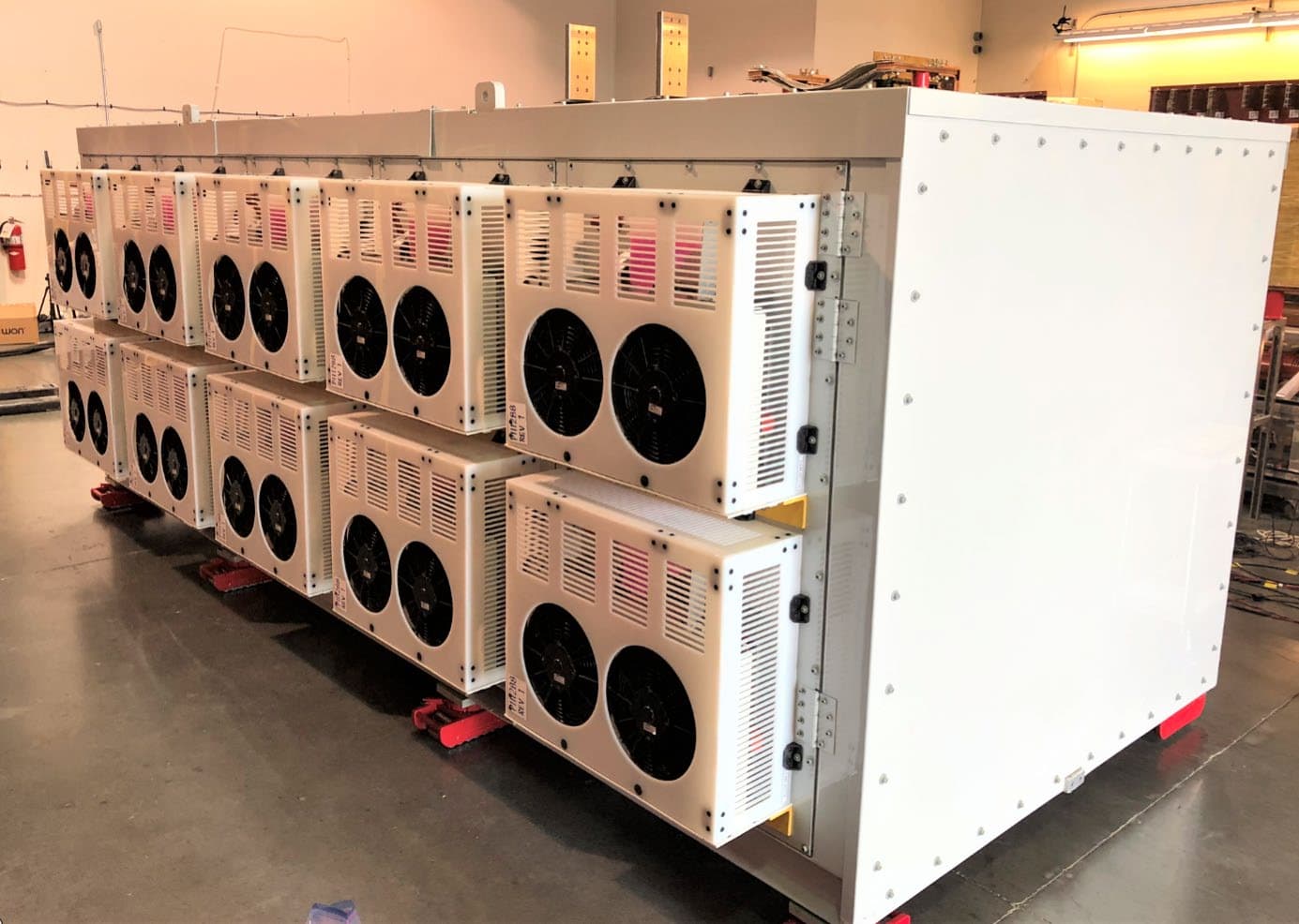
QPS01009
Feb 08, 2021SmartValve with Integrated Bypass
Equipment Class
DSS - Part 15 Spread Spectrum Transmitter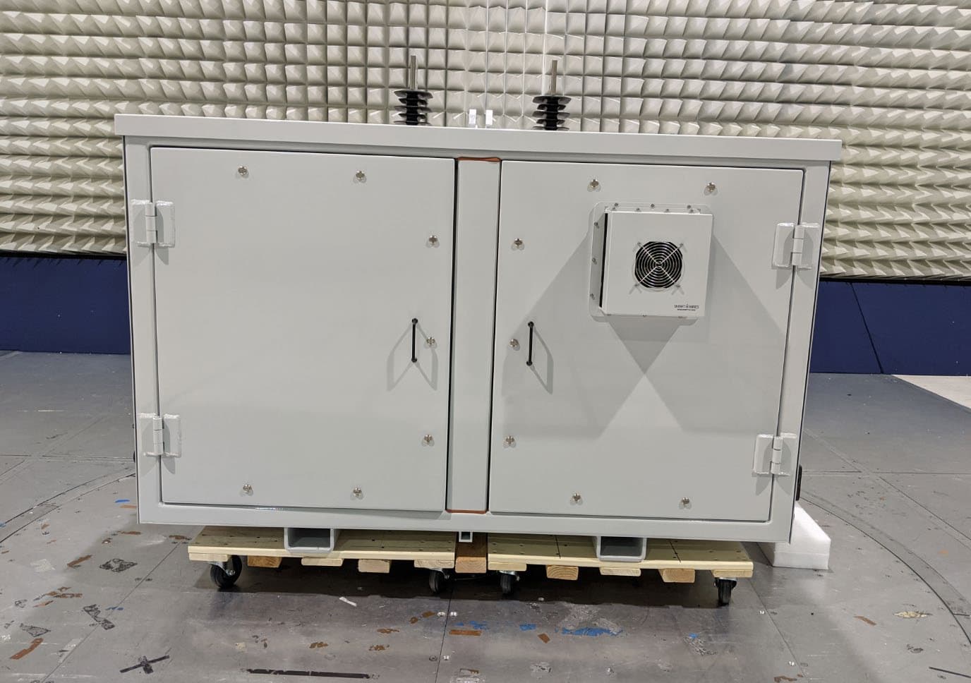
QPS01008
Jan 17, 2020SmartBypass
Equipment Class
DSS - Part 15 Spread Spectrum Transmitter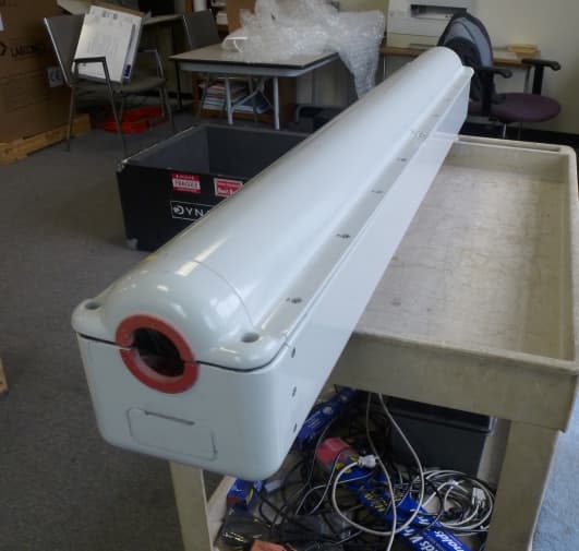
QPS01001
Feb 28, 2013DISTRIBUTED SERIES REACTANCE
Equipment Class
DXX - Part 15 Low Power Communication Device Transmitter