QPS01009SmartValve with Integrated Bypass
Smart Wires, Inc.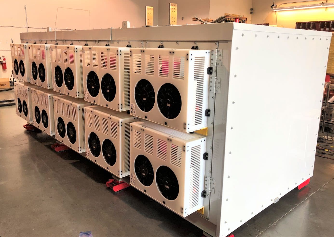
Click to zoom
Application Details
- Equipment Class
- DSS - Part 15 Spread Spectrum Transmitter
- Date of Grant
- Feb 08, 2021
- Application Purpose
- Original Equipment
- Date of Application
- Jan 26, 2021
- Equipment Note
- SmartValve with Integrated Bypass
- Frequency Range
- 902.40000000 - 926.94400000
- Company
- Smart Wires, Inc.
- Country
- United States
Documents & Files
Document Text
Text extracted from the exhibit documents filed with the FCC. Open a document above to read the original.
Users Manual
SmartValve™ with Integrated Bypass The SmartValve™ builds upon the success of its predecessors. By using revolutionary power electronics, the SmartValve effectively increases or decreases the reactance of a given circuit, enabling real-time control of power flow. A modular, Static Synchronous Series Compensator (SSSC), the SmartValve injects a leading or lagging voltage in quadrature with the line current, providing the functionality of a series capacitor or series reactor respectively. However, unlike conventional series capacitors or reactors, the SmartValve can inject the voltage independently of the line current, thus increasing the ohmic injection when operated below the rated value. Also, the SmartValve does not have the negative characteristics of these passive devices, such as the risk of sub-synchronous resonance (SSR) with series capacitors and the constant VAr consumption of series reactors. As a modular device that can be deployed and re-deployed, the solution size of an installation can be scaled up or down to support the dynamic needs of the transmission grid. Given the fast response of the unit’s power electronics, the unit can provide dynamic services and its set-point can be changed frequently to actively manage power flows with no degradation in unit life. The SmartValve enables utilities to get more from their existing grid by: • Addressing short-duration and emergency needs with rapidly deployable and easily re-deployable solutions • Accommodating changes in generation and load by deploying a fleet of units in weeks rather than years • Pushing power away from overloaded transmission facilities or pulling power onto underutilized facilities • Avoiding the use of precious substation space • Providing high uptime via a modular solution with no single point of failure The SmartValve is available with 10 MVAr and 16 MVAr ratings. The first number in the Model number designates the MVAr rating, the second is the maximum continuous current rating, the “i” indicates that a bypass is incorporated within the SmartValve and the third number is the 1 second fault rating in kA RMS. For example, Model 16-2700i-63 has a reactive power rating of 16 MVAr, a maximum continuous current rating of 2700 A RMS, an integrated bypass and 1 second fault current rating of 63 kA RMS. These units are typically installed as part of a fleet and enable a continuous range of control up to the collective rating of the deployment. SmartValve 10-1800i and SmartValve 10-3600i Dimensions 91.2in 77.8in 2316mm 1976mm 22.0in 559mm 84.3in 2141mm 55.1in 1399mm 55.1in 1399mm 22.4in 568mm 71.2in 1807mm 2376mm 10.0in 254mm 74.0in 1880mm 194.1in 4931mm 77.8in 1976mm 2269mm 74.0in 1880mm SmartValve 16-2700i Dimensions Technical Specifications Electrical Maximum Voltage Injection See Model Table below Maximum Voltage (Corona-free) 550 kV RMS line-to-line Minimum Current for Monitoring (1) 50 A RMS Power Powered by line current Minimum Current for Injection (1) 100 A RMS Operational Frequency Range 47.00 Hz – 52.00 Hz 57.00 Hz – 61.00 Hz Maximum Rate of Change of Frequency (ROCOF) Withstand 1 Hz/sec for 1s, 2 Hz/s for 0.25s Fault Current Rating (2) 63 kA RMS for 1 second Peak Fault Current Rating (2) 164 kA @ 60Hz 158 kA @ 50 Hz Physical Environmental Mass See Model Table Below Operating Ambient Temperature Range (3) -40°F to 122°F (-40°C to 50°C) Dimensions See Figure Above Storage Temperature Range -40°F to 122°F (-40°C to 50°C) Conductor Size Capacity Agnostic Condensing Operating Humidity Range 5% to 100% Mounting Deployed in a bank, suspended from structure via insulators or as part of a Mobile SmartValve Unit Maximum Sustained Rain 4.0 in/hr (102 mm/hr) Cooling Liquid-cooling interface between power semiconductors and redundant-fan-equipped liquid-to-air heat exchangers using redundant pumps all at line potential. Sealed intercoolers for controlling internal ambient temperature Intrusion Protection IEC 60529, Designed to IP 55, Tested to IP X5 Communication Other Communication Architecture EMS integration via PowerLine Gateway TM located at substation Software and Firmware Conforms to IEC 61508 SIL- 2 Communication Security Features Multilevel ISM band wireless protocol optimized for fast telemetry. Protocol uses SHA- 256 to ensure cryptographic integrity of all messages while supporting full observability by utility firewalls Electrical Connections ANSI C119.4 Sensor Accuracy AC Line Current ± 3 % Injection Mode Continuous Current Rating (A RMS) (3) Maximum Voltage Injection at 50 Hz or 60 Hz (V RMS) (4) Mass (lbs (kg)) Maximum Ramp Rate (kV/sec) (5) Monitoring Mode Continuous Current Rating (A RMS) (3, 6) Maximum 2- Hour Emergency Current (A RMS) (3, 6, 7) Model SmartValve 16-2700i-63 2700 ± 6000 26500 (12020) 25 3000 3000 SmartValve 10-3600i-63 3600 ± 2830 16000 (7257) 4 3600 4320 SmartValve 10-1800i-63 1800 ± 5660 16000 (7257) 8 1800 2160 Notes: 1. In Monitoring Mode, the SmartValve is bypassed and does not inject voltage, while telemetry data is still transmitted. In Injection Mode, the SmartValve injects voltage in series with the line and telemetry data is transmitted. 2. The following lower Fault Current Ratings are available upon request - 50.4 KA RMS for 1 second, 38 kA RMS for 1 second, 25.2 kA RMS for 1 second and 12.6 kA RMS for 1 second. 3. Current ratings of the SmartValve are dependent on the altitude and solar radiation, variations in these conditions may vary the temperature or current ratings of the SmartValve model. 4. Maximum RMS AC of the output voltage for an individual unit. Total voltage injection determined by the number of units per phase. 5. The value shown is for an individual unit. For multiple units in series, N, the maximum ramp rate of the set is N * Maximum Voltage Ramp Rate. 6. The ratings given are for operation at 50°C. Temperature-dependent ratings are available upon request. 7. Emergency current ratings apply to the SmartValve in both Injection Mode and Monitoring Mode. Ab…
Text truncated - open the document above for the full version.
Cover Letter(s)
12/14/20 Attention: Application Examiner RE: Request for Confidentiality Applicant: Smart Wires, Inc. FCC ID: QPS01009 To Whom It May Concern: SMARTE)WIRES REIMAGINE THE GRID Request is hereby submitted by Smart Wires, Inc. to withhold permanently from public review certain portions of the application for equipment certification for the referenced FCC identifiers. This request for confidentiality is made pursuant to 47 CFR 0.457(d) and 0.459 of the FCC Rules. In particular, the following sections of the application are to be kept permanently confidential: • Schematics • Detailed Block Diagrams • Detailed Operational/Functional Description Rationale for request for confidentiality: Smart Wires, Inc. has invested considerable time and materials in research and development to produce the referenced product. Disclosure of the permanently confidential portions of this application to competitors would not only give them significant competitive advantages in developing similar products, but would also disclose successful implementation of unpublished, leading edge technology developed by us. If you have questions or need further information, please contact the undersigned. ��ll)A Product Compliance Specialist S mart Wires, Inc. Smart Wires Inc. • 3292 Whipple Road • Union City, CA 94587 • T: (415) 800-5555 • www.smartwires.com
Cover Letter(s)
12/15/20 Federal Communications Commission 445 12 t h Street SW Washington, DC 20554 S ubject: Limited Agency Agreement Smart Wires, Inc. FCC ID: QPS01009 SMARTE)WIRES REIMAGINE THE GRID To Whom It May Concern: We , Smart Wires, Inc., hereby authorized lntertek Testing Services to act as our Agent for preparing application for FCC ID number QPS01009 under all applicable parts of the FCC rules and regulations. The effective date of this limited agency agreement is 12/15/2020. The Limited Agency Agreement expires on 12/15/2021, unless sooner terminated or extended by written notice to lntertek Testing Services and the Federal Communications Commission. This is to advise that we are in full compliance with the Anti-Drug Abuse Act. The applicant is not subject to a denial o f federal benefits pursuant to Section 5301 of the Anti-Drug Act of 1988, 21 U.S.C. 862, and no party to the application is subject to a denial of federal benefits pursuant to that section. If you have any questions or comments, please do not hesitate to contact me. Sincerely, Product Compliance Specialist S mart Wires, Inc. Smart Wires Inc. • 3292 Whipple Road • Union City, CA 94587 • T: (415) 800-5555 • www.smartwires.com
External Photos
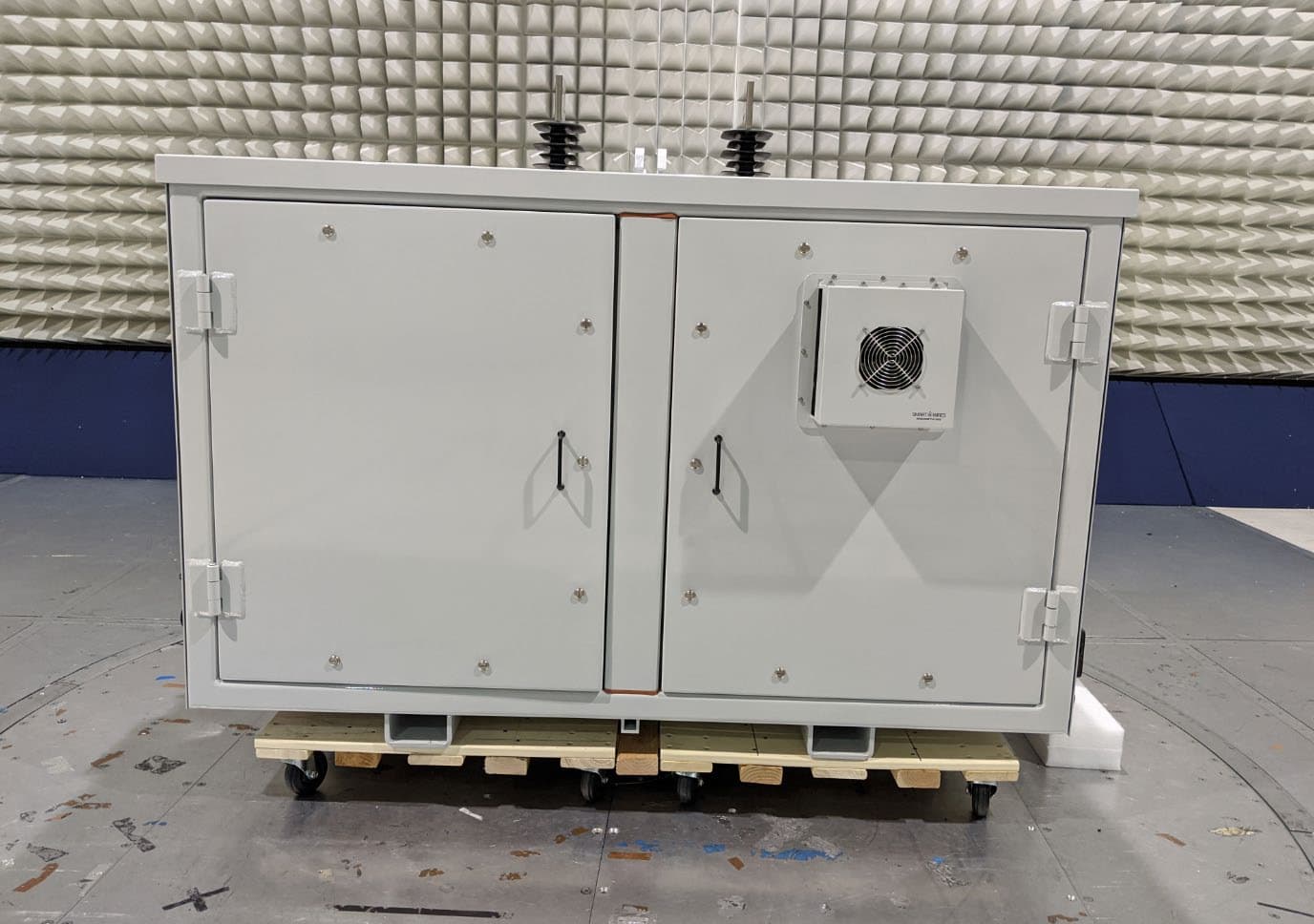
SmartValve with Integrated Bypass 10-3600i LCS side system view 1 LCS side system view 2 Enclosure Cooler Side 1 Enclosure Cooler Side 2 Top View 1 Top View 2 SmartValve with Integrated Bypass Antennas Side View 1 Side View 2
ID Label/Location Info
SmartValve TM Connection Diagram JJJYY–NNN–MVAR–MCC–FR–04 Smart Wires Inc 3292 Whipple Rd, Union City, CA 94587 USA +1 (855) 892-3340 Max. Continuous Current (Monitoring or Injection Mode): 2750 A RMS [See Note 1] Max. Emergency Current (Monitoring or Injection Mode): 2900 A RMS (2 hours) [See Note 1] Max. Reactive Power: 10 MVAr @ 3600 A RMS Max. Injected Voltage: ±2830 V RMS [See Note 3] Max. Fault Rating: 63 kA RMS for 1 s, 158 kA peak (50 Hz), 164 kA peak (60 Hz) NOTES Note 1: Applies at 45 O C ambient, 1050 W/m 2 solar radiation and 1000 m elevation. Note 2: Vertical lift only. Note 3: Device contains DC capacitors that may remain energized after device de-energization. Note 4: Refer to the O&M Manual for details and a full set of precautions. Precautions listed above are a subset. Note 5: Liquid cooling system: Material: 50/50 Ethylene glycol / water, volume: 60 liters, contains no PCBs Diagram Key: SmartValve TM Model: 10-3600i-63 Serial No: JJJYY–NNN–MVAR–MCC–FR–04 Made in USA Approximate Mass: 16000 lbs (7257 kg) [See Note 2] Mfg. Date: Month, Year Frequency: 50/60 Hz FCC ID: QPS01009 Patents Pending
ID Label/Location Info
SmartValve 10 SmartValve 10SmartValve 10SmartValve 10- ---3600i 3600i 3600i 3600i ID Nameplate Location ID Nameplate LocationID Nameplate LocationID Nameplate Location
Internal Photos
SmartValve with Integrated Bypass 10-3600i Internal Photos Enclosure Cooler side View End Panel side view LCS side internal view 2 MVar. Module RF and control PCBA P110860 iDCE Board view 1 RF and control PCBA P110860 iDCE Board view 2 P110860 iDCE PCBA RF Layout (EMC shields removed) P110860 iDCE RF PCBA (bottom view) P110860 iDCE RF PCBA Radios (close up) EMC shields removed. *. Note: 866 MHz radios are not supported in this version. LCS side with panels removed SV 10-3600i Main Internal Electromechanical systems SmartValve 10-3600i Antennas *. Note: 866 MHz radios are not supported in this version.
RF Exposure Info
Smart Wires, Inc. RF Exposure Exhibit SCOPE OF WORK EMC TESTING – SmartValve™ Model: SmartValve 10-3600i-63 REPORT NUMBER 104368457MPK-002A ISSUE DATE January 20, 2021 REVISED DATE N/A PAGES 10 DOCUMENT CONTROL NUMBER Non-Specific Radio Report Shell Rev. December 2017 MPK © 2017 INTERTEK Non-Specific Radio Report Shell Rev. December 2017 MPK EMC Report for Smart Wires, Inc. on the SmartValve™ Page 2 of 10 RF Exposure Exhibit (mobile devices) Report Number: 104368457MPK-002A Project Number: G104368457 Report Issue Date: January 20, 2021 Product Designation: Model Tested: SmartValve™ SmartValve 10-3600i-63 FCC ID: QPS01009 IC: 22326-01009 to 47CFR 2.1091 RSS-102 Issue 5 for Smart Wires, Inc. Tested by: Client: Intertek 1365 Adams Court Menlo Park, CA 94025 USA Smart Wires, Inc. 3292 Whipple Rd. Union City, CA 94587 USA Report prepared by: Report reviewed by: Anderson Soungpanya / Project Engineer Krishna Vemuri / EMC Manager This report is for the exclusive use of Intertek's Client and is provided pursuant to the agreement between Intertek and its Client. Intertek's responsibility and liability are limited to the terms and conditions of the agreement. Intertek assumes no liability to any party, other than to the Client in accordance with the agreement, for any loss, expense or damage occasioned by the use of this report. Only the Client is authorized to permit copying or distribution of this report and then only in its entirety. Any use of the Intertek name or one of its marks for the sale or advertisement of the tested material, product or service must first be approved in writing by Intertek. The observations and test results in this report are relevant only to the sample tested. This report by itself does not imply that the material, product, or service is or has ever been under an Intertek certification program. REPORT NUMBER: 104368457MPK-002A Issued: January 20, 2021 Non-Specific Radio Report Shell Rev. December 2017 MPK EMC Report for Smart Wires, Inc. on the SmartValve™ Page 3 of 10 Report No. 104368457MPK-002A Equipment Under Test: SmartValve™ Trade Name: Smart Wires, Inc. Model(s) Tested: SmartValve 10-3600i-63 Applicant: Smart Wires, Inc. Contact: Karamjit Singh Address: Smart Wires, Inc. 3292 Whipple Rd. Union City, CA 94587 USA Country: USA Tel. Number: (510) 952-2668 Email: [email protected] Applicable Regulation: 47CFR 2.1091 RSS-102 Issue 5 REPORT NUMBER: 104368457MPK-002A Issued: January 20, 2021 Non-Specific Radio Report Shell Rev. December 2017 MPK EMC Report for Smart Wires, Inc. on the SmartValve™ Page 4 of 10 TABLE OF CONTENTS Smart Wires, Inc. ............................................................................................................................................. 1 1.0 RF Exposure Summary ................................................................................................................... 5 2.0 RF Exposure Limits ........................................................................................................................ 5 3.0 Test Results (Mobile Configuration) ............................................................................................. 7 4.0 Document History ......................................................................................................................... 10 REPORT NUMBER: 104368457MPK-002A Issued: January 20, 2021 Non-Specific Radio Report Shell Rev. December 2017 MPK EMC Report for Smart Wires, Inc. on the SmartValve™ Page 5 of 10 1.0 RF Exposure Summary Test Reference FCC Reference Industry Canada Result Radio frequency Radiation Exposure Evaluation 47 CFR§2.1091 RSS-102 Issue 5 Complies 2.0 RF Exposure Limits In this document, we evaluate the RF Exposure to human body due the intentional transmission from the transmitter (EUT). The limits for Maximum Permissible Exposure (MPE) specified in FCC 1.1310 and RSS-102 are followed. 2.1 FCC Limits According to FCC 1.1310 table 1: The criteria listed in the following table shall be used to evaluate the environmental impact of human exposure to radio-frequency (RF) radiation as specified in 1.1307(b) LIMITS FOR MAXIMUM PERMISSIBLE EXPOSURE (MPE) Frequency Range (MHz) Electric Field Strength (V/m) Magnetic Field Strength (A/m) Power Density (mW/cm 2 ) Average Time (minutes) (A)Limits For Occupational / Control Exposures 0.3 – 3.0 614 1.63 *100 6 3.0 – 30 1842/f 4.89/f *900/f 2 6 30-300 61.4 0.163 1.0 6 300 - 1500 ... ... F/300 6 1500 - 100,000 ... ... 5 6 (B)Limits For General Population / Uncontrolled Exposure 0.3 – 1.34 614 1.63 *100 30 1.34 – 30 824/f 2.19/f *180/f 2 30 30 – 300 27.5 0.073 0.2 30 300 - 1500 ... ... F/1500 30 1500 - 100,000 ... ... 1.0 30 F = Frequency in MHz * = plane wave equivalent density REPORT NUMBER: 104368457MPK-002A Issued: January 20, 2021 Non-Specific Radio Report Shell Rev. December 2017 MPK EMC Report for Smart Wires, Inc. on the SmartValve™ Page 6 of 10 2.2 Industry Canada Limits According to RSS-102, Industry Canada has adopted the SAR and RF field strength limits established in Health Canada’s RF exposure guideline, Safety Code 6. Table 4: RF Field Strength Limits for Devices Used by the General Public (Uncontrolled Environment) Frequency Range Electric Field Magnetic Field Power Density Reference Period (MHz) (V/m rms) (A/m rms) (W/m 2 ) (minutes) 0.003-10 83 90 - Instantaneous* 0.1-10 - 0.73/ ƒ - 6** 1.1-10 87/ ƒ 0.5 - - 6** 10-20 27.46 0.0728 -2 6 20-48 58.07/ ƒ 0.25 0.1540/ ƒ 0. 25 8.944/ ƒ0.5 6 48-300 22.06 0.05852 1.291 6 300-6000 3.142 ƒ 0.3417 0.008335 ƒ 0.3417 0.02619 ƒ 0.6834 6 6000-15000 61.4 0.163 10 6 15000-150000 61.4 0.163 10 616000/ ƒ 1.2 150000-300000 0.158 ƒ 0.5 4.21 x 10⁻⁴ ƒ 0.5 6.67 x 10 -5 ƒ 616000/ƒ 1.2 Note: ƒ is frequency in MHz. * Based on nerve stimulation (NS). ** Based on specific absorption rate (SAR). REPORT NUMBER: 104368457MPK-002A Issued: January 20, 2021 Non-Specific Radio Report Shell Rev. December 2017 MPK EMC Report for Smart Wires, Inc. on the SmartValve…
Text truncated - open the document above for the full version.
Test Report
EMC Report for Smart Wires, Inc. on the Smar tValve™ File: 104368457MPK-001 Page 1 of 67 TEST REPORT Report Number: 104368457MPK-001 Project Numbers: G103948971, G104368457 October 19, 2020 Testing performed on the SmartValve™ Model Number: SmartValve 10-3600i-63 FCC ID: QPS01009 IC: 22326-01009 to FCC Part 15 Subpart C (15.247) ISED RSS-247 Issue 2 For Smart Wires, Inc. Test Performed by: Test Authorized by: Intertek 1365 Adams Court Menlo Park, CA 94025 USA Smart Wires, Inc. 3292 Whipple Rd. Union City, CA 94587 USA Prepared by: Date: October 19, 2020 Anderson Soungpanya Reviewed by: Date: October 19, 2020 Krishna K Vemuri This report is for the exclusive use of Intertek's Client and is provided pursuant to the agreement between Intertek and its Client. Intertek's responsibility and li abilit y are limited to the term s and conditions of the agreement. Intertek assumes no liability to any party, other than to the Client in accordance with the agreement, for any loss, expense or damage occasioned by the use of this report. Only the Client is authorized to copy or distrib ute this report and then only in its entirety. Any use of the Intertek name or one of its marks for the sale or advertisement of the tested material, product or service must first be approved in writing by Intertek. The observatio ns and test results in this report are relevant only to the sample tested. This report by itself does not imply that the material, product, or service is or has ever been under an Intertek certification program. This report must not be used to claim product endorsement by A2LA, NIST nor any other agency of the U.S. Government. EMC Report for Smart Wires, Inc. on the Smar tValve™ File: 104368457MPK-001 Page 2 of 67 Report No. 104368457MPK-001 Equipment Under Test: SmartValve™ Trade Name: Smart Wires, Inc. Model Number(s): SmartValve 10-3600i-63 Applicant: Smart Wires, Inc. Contact: Karamjit Singh Address: Smart Wires, Inc. 3292 Whipple Rd. Union City, CA 94587 Country: USA Tel. Number: (510) 952-2668 Email: [email protected] Applicable Regulation: FCC Part 15 Subpart C (15.247) ISED RSS-247 Issue 2 Date of Test: November 18 – December 10, 2019 & September 11 – 19, 2020 We attest to the accuracy of this report: Anderson Soungpanya Project Engineer Krishna K Vemuri EMC Manager EMC Report for Smart Wires, Inc. on the Smar tValve™ File: 104368457MPK-001 Page 3 of 67 TABLE OF CONTENTS 1.0 Introduction ............................................................................................................................... 4 1.1 Summary of Tests ............................................................................................................... 4 2.0 General Description ................................................................................................................... 5 2.1 Product Description ............................................................................................................ 5 2.2 Related Submittal(s) Grants ................................................................................................ 6 2.3 Test Methodology ............................................................................................................... 6 2.4 Test Facility ......................................................................................................................... 6 3.0 System Test Configuration ......................................................................................................... 7 3.1 Support Equipment ............................................................................................................. 7 3.2 Block Diagram of Test Setup ............................................................................................... 7 3.3 Justification ......................................................................................................................... 8 3.4 Mode of Operation During Test .......................................................................................... 8 3.5 Modifications Required for Compliance ............................................................................. 8 3.6 Additions, Deviations and Exclusions from Standards ........................................................ 8 4.0 Emissions Measurement Results ................................................................................................ 9 4.1 20dB Bandwidth, and 99% Occupied Bandwidth ............................................................... 9 4.2 Conducted Output Power at Antenna Terminals ............................................................. 14 4.3 Carrier Frequency Separation ........................................................................................... 19 4.4 Number of Channels ......................................................................................................... 21 4.5 Average Channel Occupancy Time ................................................................................... 24 4.6 Out-of-Band Conducted Emissions ................................................................................... 27 4.7 Transmitter Radiated Emissions ....................................................................................... 35 4.8 AC Line Conducted Emission ............................................................................................. 60 5.0 List of Test Equipment and Software ........................................................................................ 65 6.0 Document History .................................................................................................................... 67 EMC Report for Smart Wires, Inc. on the Smar tValve™ File: 104368457MPK-001 Page 4 of 67 1.0 Introduction This report is designed to show compliance of the EUT’s 900MHz transceiver with the requirements of FCC Part 15 Subpart C (15.247) and RSS-247. This test report covers only the FHSS radio. 1.1 Summary…
Text truncated - open the document above for the full version.
Test Report
EMC Report for Smart Wires, Inc. on the SmartValve™ with Integrated Bypass File: 104368457MPK-002 Page 1 of 70 TEST REPORT Report Number: 104368457MPK-002 Project Numbers: G103948971, G104368457 November 3, 2020 Testing performed on the SmartValve™ with Integrated Bypass Model Number: SmartValve 10-3600i-63 FCC ID: QPS01009 IC: 22326-01009 To FCC Part 15 Subpart C (15.247) ISED RSS-247 Issue 2 For Smart Wires, Inc. Test Performed by: Test Authorized by: Intertek 1365 Adams Court Menlo Park, CA 94025 USA Smart Wires, Inc. 3292 Whipple Rd. Union City, CA 94587 USA Prepared by: Date: November 3, 2020 Anderson Soungpanya Reviewed by: Date: November 3, 2020 Krishna K Vemuri This report is for the exclusive use of Intertek's Client and is provided pursuant to the agreement between Intertek and its Client. Intertek's responsibility and liability are limited to the terms and conditions of the agreement. Intertek assumes no liability to any party, other than to the Client in accordance with the agreement, for any loss, expense or damage occasioned by the use of this report. Only the Client is authorized to copy or distribute this report and then only in its entirety. Any use of the Intertek name or one of its marks for the sale or advertisement of the tested material, product or service must first be approved in writing by Intertek. The observations and test results in this report are relevant only to the sample tested. This report by itself does not imply that the material, product, or service is or has ever been under an Intertek certification program. This report must not be used to claim product endorsement by A2LA, NIST nor any other agency of the U.S. Government. EMC Report for Smart Wires, Inc. on the SmartValve™ with Integrated Bypass File: 104368457MPK-002 Page 2 of 70 Report No. 104368457MPK-002 Equipment Under Test: SmartValve™ with Integrated Bypass Trade Name: Smart Wires, Inc. Model Number(s): SmartValve 10-3600i-63 Applicant: Smart Wires, Inc. Contact: Karamjit Singh Address: Smart Wires, Inc. 3292 Whipple Rd. Union City, CA 94587 Country: USA Tel. Number: (510) 952-2668 Email: [email protected] Applicable Regulation: FCC Part 15 Subpart C (15.247) ISED RSS-247 Issue 2 Date of Test: November 22 – December 10, 2019 & September 11 to October 14, 2020 We attest to the accuracy of this report: Anderson Soungpanya Project Engineer Krishna K Vemuri EMC Manager EMC Report for Smart Wires, Inc. on the SmartValve™ with Integrated Bypass File: 104368457MPK-002 Page 3 of 70 TABLE OF CONTENTS 1. 0 Introduction ............................................................................................................................... 4 1.1 Summary of Tests ............................................................................................................... 4 2.0 General Description ................................................................................................................... 5 2.1 Product Description ............................................................................................................ 5 2.2 Related Submittal(s) Grants ................................................................................................ 6 2.3 Test Methodology ............................................................................................................... 6 2.4 Test Facility ......................................................................................................................... 6 3.0 System Test Configuration ......................................................................................................... 7 3.1 Support Equipment ............................................................................................................. 7 3.2 Block Diagram of Test Setup ............................................................................................... 7 3.3 Justification ......................................................................................................................... 8 3.4 Mode of Operation During Test .......................................................................................... 8 3.5 Modifications Required for Compliance ............................................................................. 8 3.6 Additions, Deviations and Exclusions from Standards ........................................................ 8 4.0 Emissions Measurement Results ................................................................................................ 9 4.1 20dB Bandwidth, and 99% Occupied Bandwidth ............................................................... 9 4.2 Conducted Output Power at Antenna Terminals ............................................................. 14 4.3 Carrier Frequency Separation ........................................................................................... 19 4.4 Number of Channels ......................................................................................................... 21 4.5 Average Channel Occupancy Time ................................................................................... 23 4.6 Out-of-Band Conducted Emissions ................................................................................... 26 4.7 Transmitter Radiated Emissions ....................................................................................... 34 4.8 AC Line Conducted Emission ............................................................................................. 63 5.0 List of Test Equipment and Software ........................................................................................ 68 6.0 Document History .................................................................................................................... 70 EMC Report for Smart Wires, Inc. on the SmartValve™ with Integrated Bypass File: 104368457MPK-002 Page 4 of 70 1.0 Introduction This report is designed to show compliance of the EUT’s 2.4GH…
Text truncated - open the document above for the full version.
Test Setup Photos
Test Setup Photos for Smart Wires, Inc. on the SmartValve™ with Integrated Bypass SmartValve™ with Integrated Bypass Model Number: SmartValve 10-3600i-63 Radiated Band Edge Setup Pictures \ Test Setup Photos for Smart Wires, Inc. on the SmartValve™ with Integrated Bypass Radiated Spurious Setup Pictures Test Setup Photos for Smart Wires, Inc. on the SmartValve™ with Integrated Bypass Test Setup Photos for Smart Wires, Inc. on the SmartValve™ with Integrated Bypass Test Setup Photos for Smart Wires, Inc. on the SmartValve™ with Integrated Bypass Test Setup Photos for Smart Wires, Inc. on the SmartValve™ with Integrated Bypass Test Setup Photos for Smart Wires, Inc. on the SmartValve™ with Integrated Bypass Test Setup Photos for Smart Wires, Inc. on the SmartValve™ with Integrated Bypass Test Setup Photos for Smart Wires, Inc. on the SmartValve™ with Integrated Bypass Test Setup Photos for Smart Wires, Inc. on the SmartValve™ with Integrated Bypass Test Setup Photos for Smart Wires, Inc. on the SmartValve™ with Integrated Bypass Conducted Emissions Test Setup
Contact Information
Applicant
Karamjit Singh
Technical Contact
Smartwires, IncKaramjit Singh
[email protected]4084642132
3292 Whipple Rd · Union City · United States
Non-Technical Contact
Smartwires, IncAaron Zhou
[email protected]5109458325
Test Firm
IntertekTesting Services NA Inc.Charles Parker
Technical Specifications
| # | Rule Parts | Frequency Range | Power Output |
|---|---|---|---|
| 2 | 15C | 902.4 MHz - 926.944 MHz | 176.10 mW |
Other Applications from Smart Wires, Inc.
QPS01008
Jan 17, 2020SmartBypass
Equipment Class
DSS - Part 15 Spread Spectrum Transmitter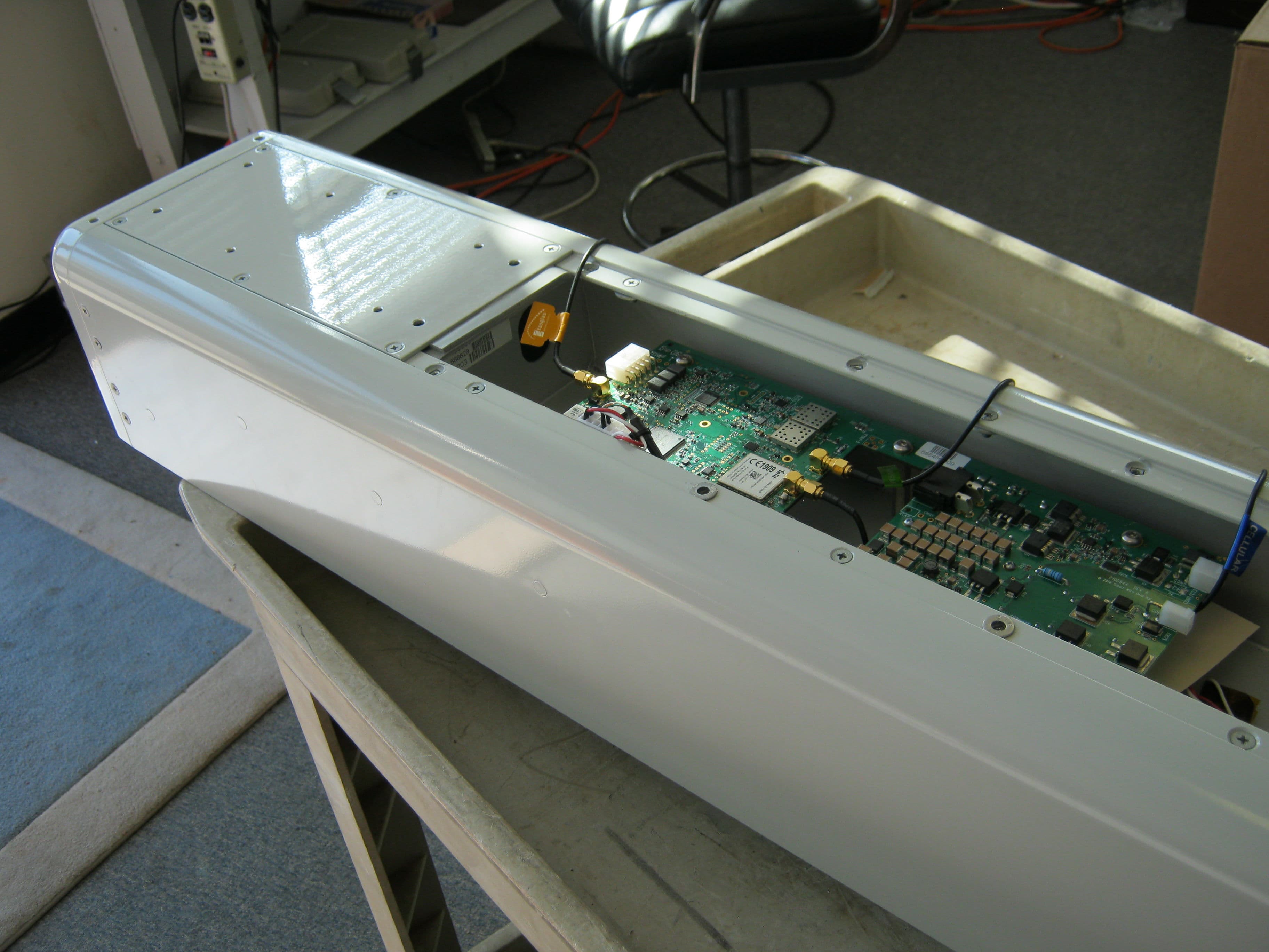
QPS01002
Dec 08, 2014Line monitor
Equipment Class
DSS - Part 15 Spread Spectrum Transmitter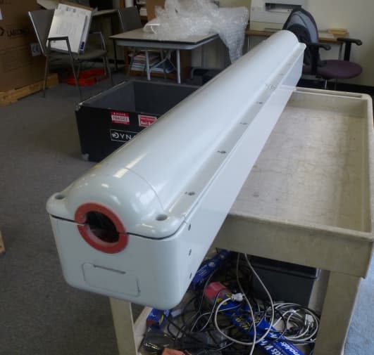
QPS01001
Feb 28, 2013DISTRIBUTED SERIES REACTANCE
Equipment Class
DXX - Part 15 Low Power Communication Device Transmitter